 Jun-Jie Zeng
 JinJing Liao
 Wen-Feng Liang1
- 1School of Civil and Transportation Engineering, Guangdong University of Technology, Guangzhou, China
- 2Department of Civil and Environmental Engineering, University of Macau, Macau, Macau SAR, China
Concrete-filled steel tube (CFST) columns have been widely used in onshore constructions. To extend its applications to coastal/offshore structures and meanwhile relieve the overexploitation on freshwater and river sand, an FRP-confined seawater sea-sand concrete-filled stainless steel tube (F-SSCFSST) column is proposed. The cyclic axial compressive behavior of this newly proposed column was investigated in this study. A total of 22 specimens (including nine pairs of specimens for cyclic compression and four individual specimens for monotonic compression) were tested. Most importantly, the influences of three loading patterns (i.e., single full unloading/reloading, repeated full unloading/reloading, and mixed of repeated full and partial unloading/reloading) were studied. The results showed that although all F-SSCFSST specimens failed from FRP rupture in the mid-height area, the FRP rupture was less fierce for specimens with repeated internal unloading/reloading cycles. Similar to the FRP-confined concrete, the envelope curve of cyclic axial load–strain response matched closely with the monotonic compression curve for a particular specimen. However, the unloading curve was less curly compared with that of a typical FRP-confined concrete. The confinement effect provided by the FRP jacket was much stronger than that by the stainless steel tube. Although Lam and Teng’s model, which is proposed for the FRP-confined concrete, could provide satisfactory estimations for strain recovery ratios and stress deterioration ratios, it underestimated the envelope plastic strains by 20%.
Highlight
• Confinement by the FRP jacket is much stronger than that of the stainless steel tube.
• Different cyclic loading protocols have little effect in ultimate load carrying capacity.
• The unloading curve is less curly compared with that of the FRP-confined concrete, and thus Lam and Teng’s model underestimates the envelope plastic strain by 20%.
• Lam and Teng’s model can still yield satisfactory strain recovery ratio and stress deterioration ratio.
Introduction
Concrete-filled steel tube (CFST) columns have been increasingly used in onshore structures. The confinement provided by the outer steel tube can restrain the dilation of the concrete core, and thus enhance the axial load carrying capacity and ductility of the column (Ellobody et al., 2006; Wang et al., 2013; Hou et al., 2014; Wang et al., 2017; Geng et al., 2020). A number of studies have delved into the compressive behavior of CFST columns with different in-filled concrete strength, steel tube strength, and steel tube shapes (Xiao et al., 2005; Xiong et al., 2017; Wang et al., 2018; Wei et al., 2019; Ouyang et al., 2020; Liao et al., 2021a). It is generally concluded that the specimens exhibit a load plateau after steel tube yielding (Xiao et al., 2005; Xiong et al., 2017; Wang et al., 2018; Wei et al., 2019; Ouyang et al., 2020; Liao et al., 2021a). However, when utilized in coastal/offshore constructions (e.g., cross-sea bridges), the traditional CFST columns have two major drawbacks. First, corrosion issues may not only emanate from the outer surface of the steel tube which contacts seawater directly but also arise from the inner surface. To date, seawater sea-sand concrete (SSC) has been widely used in maritime constructions as a substitution for conventional concrete due to two advantages: 1) relief of over-exploitation on freshwater and river-sand; and 2) significant cutdown on raw material transportation costs (Zeng et al., 2020a; Zeng et al., 2020b; Ye et al., 2021). As a result, chloride ions in SSC will also pose corrosion threats to the inner surface of steel tubes. Second, the composite action between the steel tube and concrete core is weak because they have different Poisson’s ratio values (typically 0.3 for the steel tube and 0.2 for the concrete) (Zeng et al., 2020c; Zeng et al., 2021a). This suggests that during compression, delamination failure and the following steel tube local buckling would impair the strength and ductility of CFST columns (Zeng et al., 2020c; Zeng et al., 2021a).
To resolve the corrosion drawback, the stainless steel tube (SST) has been proposed to replace the carbon steel tube in CFST columns (Guo et al., 2019; Tan et al., 2020; Qiao et al., 2021). Stainless steel not just has better corrosion resistance than carbon steel but also has improved fire and fatigue performance (Qiao et al., 2021). In terms of mechanical properties, stainless steel usually exhibits significant strain hardening characteristics and does not show a yield plateau as carbon steel (Qiao et al., 2021). However, due to the less carbon content, stainless steel is softer in strength than carbon steel (Han et al., 2019). Investigations on confinement performance of the SST are also abundant (Guo et al., 2019; Han et al., 2019; Dai et al., 2020; Tan et al., 2020; Qiao et al., 2021). These investigations can be divided into two groups, one is for concrete-filled stainless steel tube (CFSST) columns in which an SST not only provides confinement but also resists the axial load; the other one is called stainless steel tube confined concrete (SSTCC) in which an SST does not participate in carrying axial load (Tan et al., 2020). It is interesting to find that the load-carrying capacity of an SSTCC column is greater than that of a CFSST column (Tan et al., 2020), and the ductility of an SSTCC column can also be improved as the local buckling of the SST is delayed (Qiao et al., 2021). The second major drawback (i.e., weak composite action) mentioned above can be remedied by applying an external fiber-reinforced polymer (FRP) jacket over CFST columns. The FRP material has a very high strength-to-weight ratio and has been extensively used in civil engineering (Wu and Jiang, 2013; Liao et al., 2021b; Wei et al., 2021; Zhou et al., 2021; Liao et al., 2022a; Zeng et al., 2022a; Liao et al., 2022b; Zeng et al., 2022b; Mo et al., 2022; Pan et al., 2022). During axial compression, FRP confinement not only improves the composite action between the steel tube and concrete core but also delays (or to some extent prevent) the outward bulging of the steel tube. As a result, both strength and ductility of the specimen can be enhanced. The typical axial compressive response of an FRP-confined CFST column consists of a load hardening branch after the FRP jacket is fully activated (Tao et al., 2007; Gholampour and Ozbakkaloglu, 2018; Zhang et al., 2019; Zhang et al., 2020a; Wei et al., 2020), which is different from the response of a CFST column. A theoretical model has been proposed by Teng et al. (Teng et al., 2013) to predict the stress–strain behavior of the confined concrete in FRP-confined CFST columns. Apparently, the application of both the SST and FRP jacket can resolve the two major drawbacks at the same time. Currently, only Tang et al. (Tang et al., 2020) has conducted experimental research on FRP-confined concrete-filled SST columns. However, Tang et al.’s study (Tang et al., 2020) only focused on the monotonic compressive behavior.
To date, the majority of investigations on the cyclic compressive behavior of confined concrete are still concentrated on FRP-confined concrete (Lam and Teng, 2009; Ozbakkaloglu and Akin, 2011; Li and Wu, 2015). For example, Lam and Teng (Lam and Teng, 2009) have developed a stress–strain model for FRP-confined concrete under cyclic compression, including the predictions of a single unloading/reloading cycle at each prescribed unloading occasion, and multiple repeated internal unloading/reloading cycles at each prescribed unloading occasion. Li and Wu (Li and Wu, 2015) proposed another stress–strain model with simplified mathematical forms. Ozbakkaloglu and Akin (Ozbakkaloglu and Akin, 2011) accounted for the impacts of concrete type on the model. To our best knowledge, only Yu et al. (Yu et al., 2014) and Zhang et al. (Zhang et al., 2020b) have studied the cyclic compressive stress–strain behavior of the FRP-confined CFST. Yu et al.’s model (Yu et al., 2014) is further developed on the basis of Lam and Teng’s model (Lam and Teng, 2009), although the predictions of Yu et al.’s model (Yu et al., 2014) had high level of accuracy, the method was too complicated that it may be more suitable for computer programs. By contrast, Zhang et al.’s model (Zhang et al., 2020b) is a design-oriented model that has much simpler mathematical forms. It is of particular importance to gain in-depth understanding on the cyclic compressive behavior of the FRP-confined SSC-filled SST (F-SSCFSST), which is fundamental for the reliable seismic design for the hybrid column form. Nevertheless, the cyclic axial compressive behavior of the F-SSCFSST columns has not been explored yet.
In this light, axial cyclic compression tests were performed for F-SSCFSST specimens in this study. The effects of SST thickness, FRP thickness, and cyclic loading protocols were under investigation. In addition, the applicability and accuracy of Lam and Teng’s model (Lam and Teng, 2009) were evaluated and discussed by analyzing three key parameters (plastic strain, strain recovery ratio, and stress deterioration ratio).
Test Program
Specimen Details
In total, 22 specimens, including nine pairs for cyclic axial compression (two duplicated specimens in a pair) and four individual specimens for monotonic axial compression, were fabricated and tested. All specimens had the same size (219 mm in outer diameter × 500 mm in height) and were filled with the same batch of concrete (normal strength SSC). The nine pairs of specimens under cyclic compression can be divided into two groups as per the SST thickness (2 and 4 mm, denoted by “SST2” and “SST4”, respectively). The majority of the cyclic compression specimens were in the SST4 group, in which three external FRP jacketing configurations were prepared: 1) no FRP confinement (denoted by “F0”); 2) confined with 2-ply CFRP jackets (denoted by “F2”); 3) confined with 4-ply CFRP jackets (denoted by “F4”). For comparison, only 2-ply CFRP external wrapping was applied to the specimens in group SST2. Therefore, there were four primary F-SSCFSST specimen configurations (the SSCFSST specimen with no FRP confinement can be seen as a special case of the F-SSCFSST specimen). For each primary specimen configuration, two loading protocols were applied: they are single full unloading/reloading cycle at each prescribed unloading point (denoted by “L1”) and four repeated full unloading/reloading cycles at each prescribed unloading point (denoted by “L2”). In addition, an additional loading protocol (i.e., combination of repeated full and partial unloading/reloading cycles at each prescribed unloading point, denoted by “L3”) was considered for the F-SSCFSST specimen with a 4-mm-thick SST and 2-ply CFRP jacket. The three types of loading protocols are elaborated in Loading Protocol Section. Correspondingly, the four primary F-SSCFSST specimen configurations were also tested under monotonic axial compression, serving as the references for their counterparts under cyclic compression. The specimen details are given in Table 1.
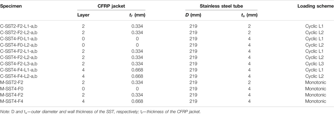
TABLE 1. Specimen details.
The specimens were named in the following convention: “loading type (i.e., “M” for monotonic compression, “C” for cyclic compression)”–“SST tube specification (i.e., SST2 and SST4)”–“CFRP confinement configuration (i.e., F0, F2, and F4)”–“loading protocol for cyclic compression (i.e., L1, L2, and L3)”–“identifications for the two duplicates (i.e., letters “a” and b)”. For example, C-SST4-F2-S4-L2-b signifies that the specimen is the second duplicate in the pair of the F-SSCFSST specimens with the 4-mm-thick SST and 2-ply CFRP jacket, which is subjected to cyclic axial compression of loading protocol L2.
Material Properties
The specimens were made of three materials: CFRP sheets, SSTs, and SSC. The CFRP sheets were purchased from Toray Industries, Inc., which were manufactured with a nominal thickness of 0.167 mm per layer. Standard coupons tests as per ASTM D3039/D3039M-17 (ASTM D3039/D3039M-17, 2014) were performed for five CFRP samples. The tensile strength (
The stainless steel tubes were seamless tubes supplied by a local producer complying with the ATSM standard (ASTM A959, 2009). The SSTs had two wall thickness specifications (2 and 4 mm) but the same height (500 mm) and outer diameter (219 mm). Three standard coupons were cut from each specification of the SST and tested as per BS 18 (BS 18, 1987). The test curves are shown in Figure 1. The key test results are given in Table 2, in which the yield strength of stainless steel is taken as 0.2% proof stress (Liao and Ma, 2018a; Liao and Ma, 2018b; Han et al., 2019).
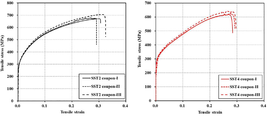
FIGURE 1. Test curves of stainless steel tube coupons.
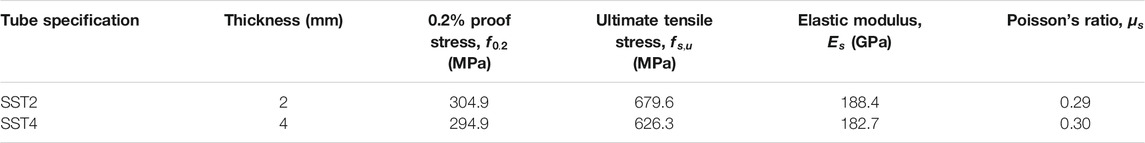
TABLE 2. Material properties of stainless steel tubes.
The mix proportions of the SSC are given in Table 3. Sea-sand was harvested from the shores near Yingde and Lianzhou, China. Seawater was simulated using the same ingredients from our previous studies (Zeng et al., 2020a), and the synthesis process followed the ASTM standard D1141 (ASTM D1141, 2013). The SSC was mixed manually in the structural lab of Guangdong University of Technology. According to ASTM C469 (ASTM C469 and C469M-14, 2014), three standard cylinders (150 mm in diameter × 300 mm in height) were prepared for concrete strength tests. The average compressive strength (
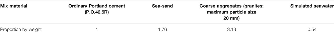
TABLE 3. Mix proportions of seawater sea-sand concrete.
Loading Protocol
The monotonic axial compression load was applied to the specimens continuously until the axial strain reached 10%, whereas the cyclic axial compression involved a number of unloading/reloading cycles. There were three loading protocols considered for cyclic axial compression in this study, which are illustrated in Figure 2. Cyclic loading protocol L1 was known as the single full unloading/reloading cycle, that is, at each prescribed unloading strain, only one full unloading/reloading cycle was imposed to the specimens. In this study, the unloading was terminated at a very small load close to zero (i.e., 120 kN, approximately 3.2 MPa) to maintain functionality of the test machine. The reloading was terminated when the reloading strain returned to the prescribed unloading strain. Then, the loading was continued to the next prescribed unloading strain.
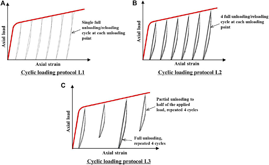
FIGURE 2. Cyclic loading protocols. (A) Cyclic loading protocol L1. (B) Cyclic loading protocol L2. (C) Cyclic loading protocol L3.
Cyclic loading protocol L2 was also concerned with full unloading/reloading cycles. However, L2 was different from L1 such that at each prescribed unloading strain, four repeated full internal unloading/reloading cycles were applied to the specimens, instead of a single full unloading/reloading cycle for L1. The unloading rule for L2 was the same as those for L1, while there were small differences for the reloading rule. For the first three internal cycles (n ≤ 3), the reloading was terminated when reaching the prescribed unloading strain, and then unloading started for the next internal cycle, whereas for the fourth internal cycle (n = 4), when reloading strain recovered to the prescribed unloading strain, the loading was continued to the next prescribed unloading strain.
Cyclic loading protocol L3 was mixed with full and partial repeated unloading/reloading cycles, each with four repeated internal cycles, that is, full repeated unloading/reloading cycles were applied at the first prescribed unloading strain, followed by a partial repeated unloading/reloading cycle at the second prescribed unloading strain, and another full repeated unloading/reloading cycle at the third prescribed unloading strain, and so on. In other words, full repeated unloading/reloading cycles occurred at an odd number of prescribed unloading strains, while partial repeated unloading/reloading cycles occurred at the even numbers. The magnitude of partial unloading was 50% of the applied load at the corresponding prescribed unloading strain. The unloading and reloading rules for the internal cycles of L2 were also applicable for L3. The three cyclic loading protocols can be programed by the test machine.
Test Setup
The axial shortening of each specimen was measured by three sets of instruments: 1) four axial strain gages (SGs, gage length of 20 mm) pasted at the mid-height at every 90° radially (one of the SGs was in the middle of the overlapping zone); 2) four axial liner variable differential transducers (LVDTs) mounted at the same positions of the four axial SGs but over a 200-mm-long region at the mid-height (LVDT-200); 3) another two LVDTs set up between the two loading platens (apart by 180°) to monitor the total shortening over the full height (LVDT-500). The dilation of the specimens was also recorded by the means of SGs and LVDTs. Four hoop SGs were also glued at the mid-height next to the four axial SGs, but in the horizontal direction. In addition, two horizontal LVDTs set apart by 180° in the line orthogonal to the two LVDT-500s were also installed. The instrumentation diagram is illustrated in Figure 3A.
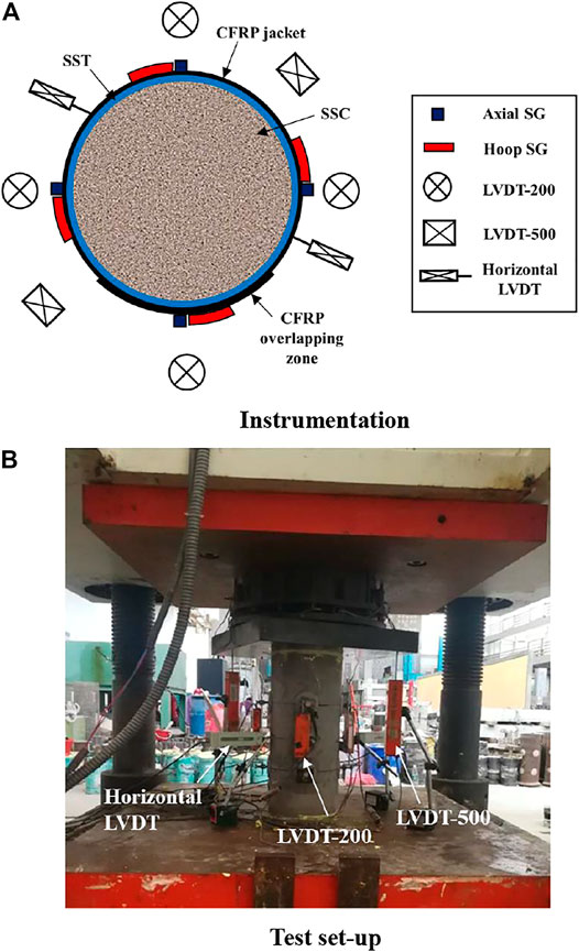
FIGURE 3. Instrumentation and test setup. (A) Instrumentation. (B) Test setup.
Before mounting to the test machine, two 50-mm-wide CFRP strengthening strips were applied to both ends of each F-SSCFSST specimen, while SSCFSST specimens were left unstrengthened. In addition, thin layers of gypsum mortar were adopted for leveling. The axial compression tests were performed with a 1000-ton compression machine (YAW-10000F); the test setup is shown in Figure 3B. Pre-loads up to around 11 MPa were applied to check the functionality of the instruments and the alignments of the loading. The formal tests were performed with a loading rate of 0.6 mm/min and an unloading rate of 1 mm/min. For SSCFSST specimens, the tests were terminated when axial displacement reached 50 mm (i.e., 10% axial strain), while the tests were terminated when significant FRP rupture occurred for F-SSCFSST specimens.
Test Results and Discussion
Failure Modes
The failure modes of the specimens under cyclic compression are shown in Figure 4. It is seen that the two pairs of SSCFSST specimens were subjected to elephant foot buckling at both ends. This type of failure mode is different from the typical failure mode of CFST specimens reported in the previous studies (Xiao et al., 2005; Xiong et al., 2017; Wang et al., 2018; Wei et al., 2019; Ouyang et al., 2020; Liao et al., 2021a), in which concrete shear failure was the main cause and steel tube buckling tended to occur in both middle upper and middle lower regions, coinciding with the major shear crack of the concrete core. By contrast, elephant foot buckling usually occurs for hollow tubes, and thus the results implied that the bond between the SST and SSC was very weak, especially at the two loading ends. The SST is much smoother than a steel tube, and the cyclic loading would further weaken the bond between the SST and SSC.
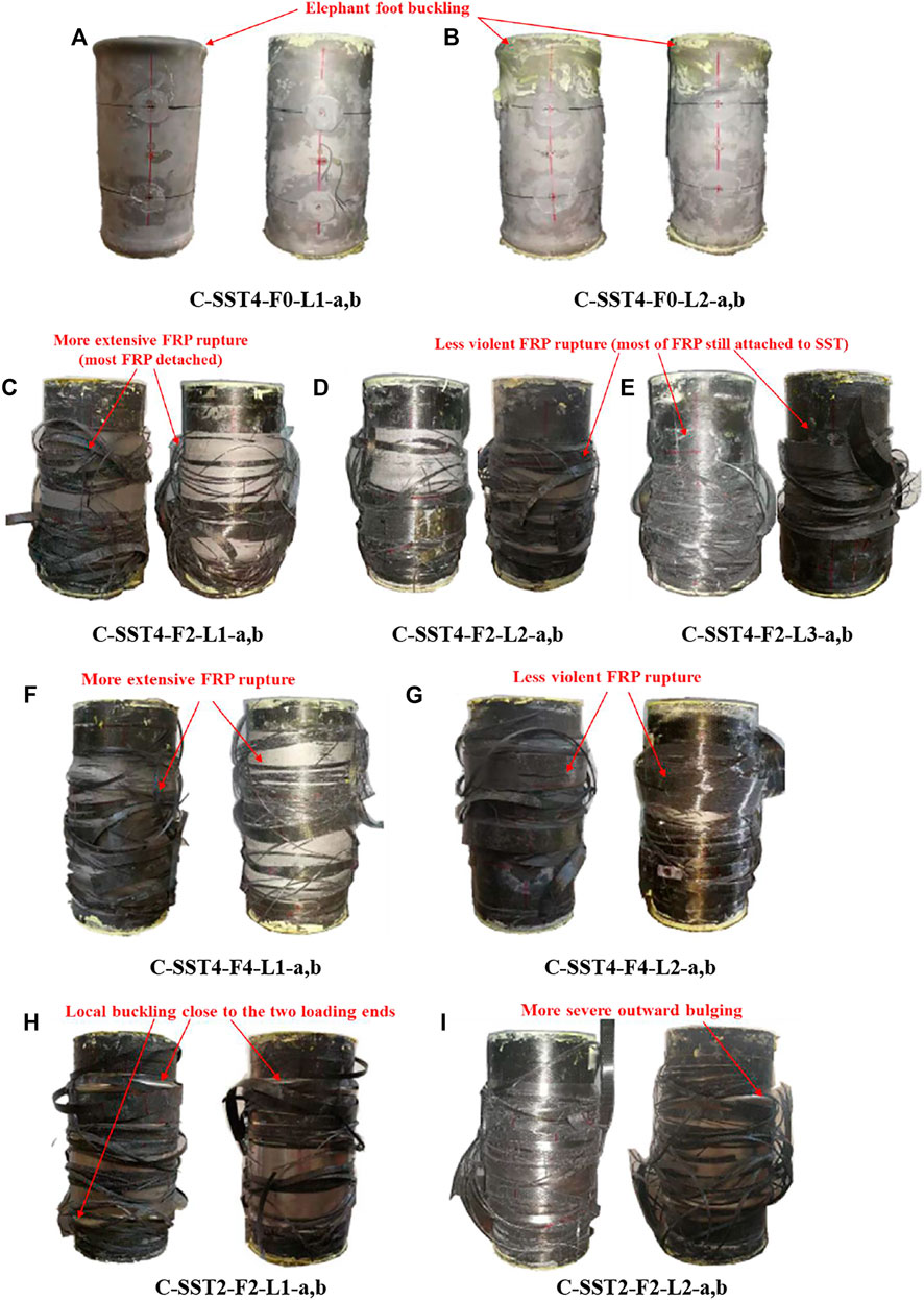
FIGURE 4. Failure modes for the specimen under cyclic compression. (A) C-SST4-F0-L1-a,b. (B) C-SST4-F0-L2-a,b. (C) C-SST4-F2-L1-a,b. (D) C-SST4-F2-L2-a,b. (E) C-SST4-F2-L3-a,b. (F) C-SST4-F4-L1-a,b. (G) C-SST4-F4-L2-a,b. (H) C-SST2-F2-L1-a,b. (I) C-SST2-F2-L2-a,b.
For F-SSCFSST specimens, elephant foot buckling did not occur as both ends of the specimens were sufficiently strengthened. However, local buckling still occurred in the other locations of the SSTs. For specimens confined with 2-ply CFRP sheets, SST local buckling was more frequently seen in the upper or lower regions close to the loading ends, whereas local buckling was less prominent for most of the specimens with 4-ply CFRP wrappings, and the outward expansion was usually at the mid-height region. This observation is consistent with Zhang et al.’s report for FRP-confined CFST specimens (Zhang et al., 2020b), indicating that when confined with FRP jackets, specimens with SST or the conventional steel tube did not have fundamental difference in the failure mode. It is also observed that specimens with a 2-mm-thick SST were subjected to more severe outward bulging because the slenderness ratio of SST2 was twice that of SST4.
FRP rupture is another characteristic failure mode for F-SSCFSST specimens. All ruptures occurred at or close to the mid-height region and propagated rapidly to the upper and lower regions simultaneously, unzipping the majority of the CFRP jacket. When observed carefully, it is revealed that the FRP rupture for specimens under repeated internal cycles (i.e., loading protocol L2 and L3) was less fierce than for those under single cycles (i.e., L1). C-SST4-F2-L3 and C-SST4-F4-L2 specimens were the clear examples that most of the CFRP wrappings were still adhered to the tubes. This could be because the repeated loadings have already caused damages to some FRP wrappings (e.g., some FRP strings already severed), and hence the ultimate FRP rupture was less extensive and drastic.
Axial Load–Strain Behavior
The axial load–strain curves are shown in Figure 5, in which the curves for monotonic and cyclic compression tests are plotted together. The axial strains were obtained as a hybrid record of axial SGs and LVDT-500 (i.e., records were continued with the LVDT-500 data, when SGs malfunctioned), which has been frequently used in a number of similar studies (Zeng et al., 2020a; Zeng et al., 2020b; Zeng et al., 2020c; Zeng et al., 2021a; Ye et al., 2021). The close match of the axial load–strain curves in each pair of duplicated specimens demonstrated the repeatability of the test results. The typical responses of F-SSCFSST specimens under monotonic compression consisted of three branches (an initial ascending branch representing the elastic response; a transition branch; and a response hardening branch, which can also be treated as a second linear ascending branch), whereas axial load–strain curves of SSCFSST specimens under monotonic compression were subjected to load reductions due to buckling of SSTs.
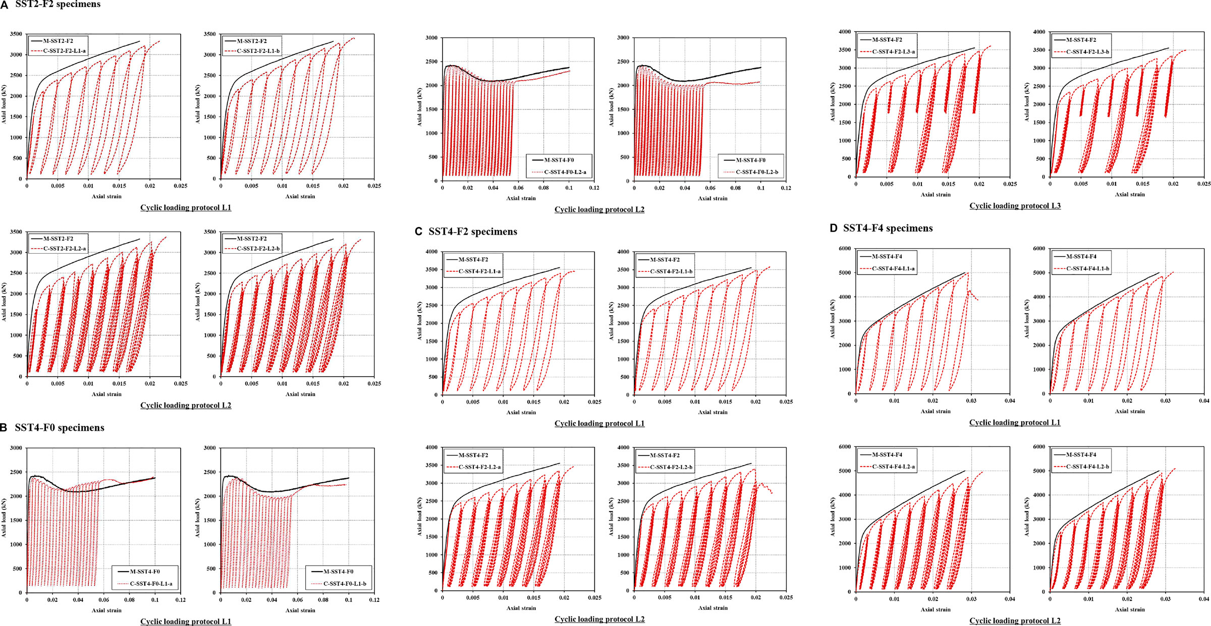
FIGURE 5. Axial load–strain curves. (A) SST2-F2 specimens. (B) SST4-F0 specimens. (C) SST4-F2 specimens. (D) SST4-F4 specimens.
In terms of cyclic responses, for all three loading protocols, the plastic strains of the specimens increased with the progress of the prescribed unloading strains. The unloading and reloading curve in each cycle can be clearly viewed from loading protocol L1. The reloading curve was almost linear until it reached the new stress point, while the unloading curve was nonlinear, which can be approximated by an almost straight line in the early stage of unloading and a polynomial curve when the applied load was unloaded by around 75%, after which the curvature of the unloading curve became noticeable due to FRP confinement slack (Zeng et al., 2021b). The progressive decreasing slope along the unloading curve in the late stage signified the deterioration of the concrete core. However, the unloading curves for specimens under loading protocol L3 were generally linear, and thus the reloading and unloading curves overlapped with each other. For those specimens under loading protocol L2 and L3, at each prescribed unloading occasion, the plastic strains of the repeated full internal cycles increased marginally with the advancement of internal cycles, and the new stresses recovered to the specific prescribed unloading strain decreased with the increasing internal cycle numbers. Generally, these cyclic responses of F-SSCFSST columns are similar to the typical cyclic behaviors of the FRP-confined concrete (Lam and Teng, 2009); however, the unloading curve seemed to be less curly in the low stress stage. This is concerned with the plastic strains which are discussed in detail in Plastic Strain Section.
When comparing the cyclic responses with monotonic responses for the specimens with the same configurations, it is seen that in each chart, the envelope curve of cyclic response generally matched closely with the monotonic axial load–strain curve (the differences were around 10%). Furthermore, the different cyclic loading protocols (i.e., L1, L2, and L3) seemed to have little impact on the envelope curve of the specimens. This result pattern is consistent with Yu et al.’s findings on FRP-confined CFST columns (Yu et al., 2014) and Lam and Teng’s finding on FRP-confined concrete (Lam and Teng, 2009). Thus, the monotonic axial load–strain curve of an F-SSCFSST specimen may be taken as the upper bound of the cyclic response of that specific specimen, regardless of the cyclic loading protocols. In addition, using the SSC did not change the general result pattern either; this is expected as a number of previous investigations have concluded that the short-term mechanical performance between the SSC and conventional concrete casted with the same proportion of freshwater and river sand was minimal (Liao et al., 2022a; Zeng et al., 2022b), and the stress–strain responses of the FRP-confined SSC were also very similar to those of the FRP-confined conventional concrete (Zeng et al., 2020a; Zeng et al., 2020b).
The ultimate loads and axial strains of both monotonically and cyclically loaded specimens are summarized in Table 4. It is also noticed that ultimate loads of the specimens with the same configurations also appeared to be independent of cyclic loading protocols. The SST4-F2 specimens were typical examples, in which the ultimate load capacity under monotonic axial compression was 3,555.8 kN. While the ultimate loads extracted from the three cyclic loading protocols (i.e., L1, L2, and L3) were 3,523.3, 3,434.2, and 3,552.2 kN, respectively, the maximum difference was just 3.5%. However, the ultimate axial strains of cyclic responses were generally 10–20% greater than those of monotonic curves from their counterparts. The repeated loading can significantly weaken the concrete, making the specimens compacter (i.e., more axial shortening).
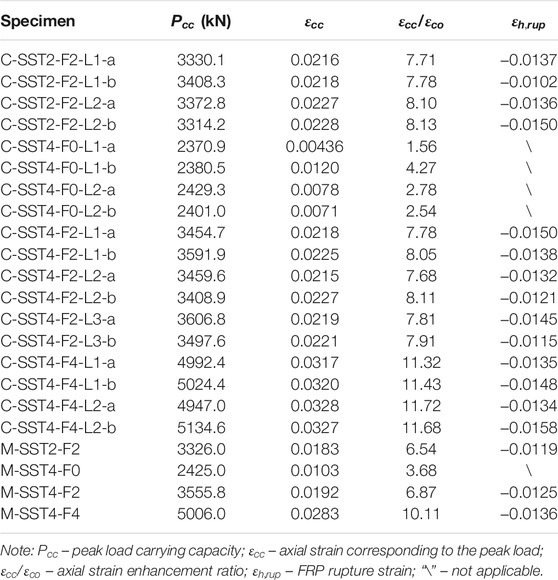
TABLE 4. Summary of key test results.
Dilation Behavior
The dilation behavior is illustrated by the axial strain–hoop strain curves of some selected specimens in Figure 6. The data of the three hoop SGs outside of the overlapping zone were used to compute the average hoop strains. The axial strain–hoop strain curves presented in Figure 6 were terminated when hoop SGs were broken. The horizontal LVDTs cannot capture the hoop strain as smoothly as the hoop SGs, and thus LVDT results are not presented. Nevertheless, the data from hoop SGs can still reveal some general result trends.
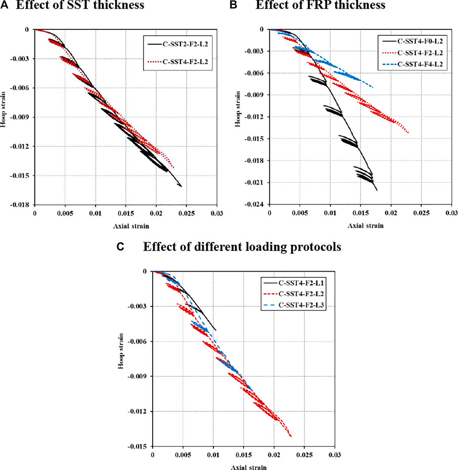
FIGURE 6. Axial strain–hoop strain curves of representative specimens (SG data only). (A) Effect of SST thickness. (B) Effect of FRP thickness. (C) Effect of different loading protocols.
Similar to the axial load–strain curves, the envelope curve of the cyclic axial strain–hoop strain curves also exhibited a roughly linear relation after the confinements were fully activated. The slope of this roughly linear envelope curve after full activation is a clear indicator for the confinement effect and damage of the concrete core, as the dilation (i.e., concrete cracking) can be restrained. The effect of SST thickness is compared in Figure 6A using C-SST2-F2-L2 and C-SST4-F2-L2 as examples. It is shown that under a particular FRP confinement and the same loading scheme, the dilation curves of these two specimens had very close slopes for the full activation branch, except for the dilation of C-SST2-F2-L2 which was a little larger than that of its counterpart. For example, the maximum hoop strain for C-SST4-F2-L2 before the hoop SG failure was -0.014, while at the same axial strain, the hoop strain of C-SST2-F2-L2 was only 7% greater at -0.015. This result indicates that the confinements provided by the SST were insignificant such that doubling the SST thickness did not lead to noticeable changes in the slope. However, as shown in Figure 6B, increasing FRP confinement thickness can significantly reduce the slope of the envelope curve after full activation when the SST thickness and loading scheme remained the same. A quick assessment using the secant slope at the maximum hoop strains of the three specimens revealed that when comparing to the SST4-F0 specimen, the secant slope has been reduced by 60% for 2-ply FRP jacket and 70% for 4-ply FRP jacket. These results suggested that the confinement effect provided by FRP is much stronger than that of the SST. The damages to the concrete core from different loading schemes can be inferred from Figure 6C using SST4-F2 specimens as examples. It is seen that both L2 and L3 cyclic curves were located below the L1 curve, indicating that increasing internal cycles have caused more damages to the concrete core. When comparing carefully, it is also noticed that the dilations of the L2 curve was a little greater than those of the L3 curve, especially in the early stage of the tests. This is because under partial repeated unloading (L3), the FRP confinement pressure was still high, and thus the cracking could be restrained (Zeng et al., 2021b), while for full repeated unloading (L2), the FRP confinement would sack in the end stage of unloading, during which concrete cracks and crushing damages tended to occur more easily. However, with the progress of the prescribed unloading strain, the concrete core has been deteriorated to a certain degree such that the dilation between L2 and L3 curves became less noticeable.
Analysis of Key Parameters
Note that the key parameters discussed in this section are based on stress-strain curves of confined concrete in F-SSCFSSTs. The “stress” is referred to as the average axial stress carried by the concrete core. The axial load carried by the concrete core can be obtained by subtracting the load contribution of SSTs from the total axial load, and the axial stress in SSTs was computed using the plasticity increment theory which has been detailed in our previous study (Zeng et al., 2021a).
Lam and Teng’s cyclic model (Lam and Teng, 2009) is one of the typical models that has good performance and wide applicability. As shown in Figure 7, the cyclic portion of the model can be divided into two segments: an unloading segment and a reloading segment. The unloading segment starts from the prescribed unloading strain (
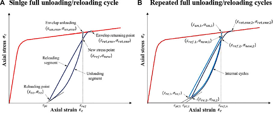
FIGURE 7. Schematic view of Lam and Teng’s model (Lam and Teng, 2009). (A) Single full unloading/reloading cycle. (B) Repeated full unloading/reloading cycles.
The aforementioned behavior is very similar to that observed in the current experimental study. Thus, although Lam and Teng’s model (Lam and Teng, 2009) is derived for the FRP-confined concrete, it may still be applicable for the F-SSCFSST with minor modifications, which can be evaluated by assessing some key model parameters. As briefed above, the reloading points and new stress points are essential to determine the cyclic response curves; therefore, the applicability and performance of Lam and Teng’s model (Lam and Teng, 2009) can be evaluated by assessing the accuracy of plastic strains, strain recovery ratios, and stress deterioration ratios.
Plastic Strain
The plastic strain (
Using the specimens of loading protocol L2 as examples, the developments of plastic strains are shown in Figure 8, in which the plastic index is defined as the ratio of the plastic strain to unloading strain (
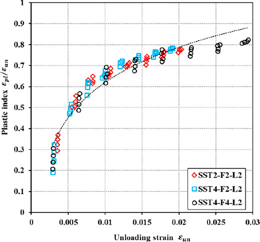
FIGURE 8. Development of plastic strains.
The plastic strain of the envelope cycle (
However, the abovementioned findings are concerned with the FRP-confined concrete. Given the dual confinement of the steel tube and FRP jacket, Zhang et al. (Zhang et al., 2020b) considered that the relationship between
An assessment of the accuracy of the two prediction equations for
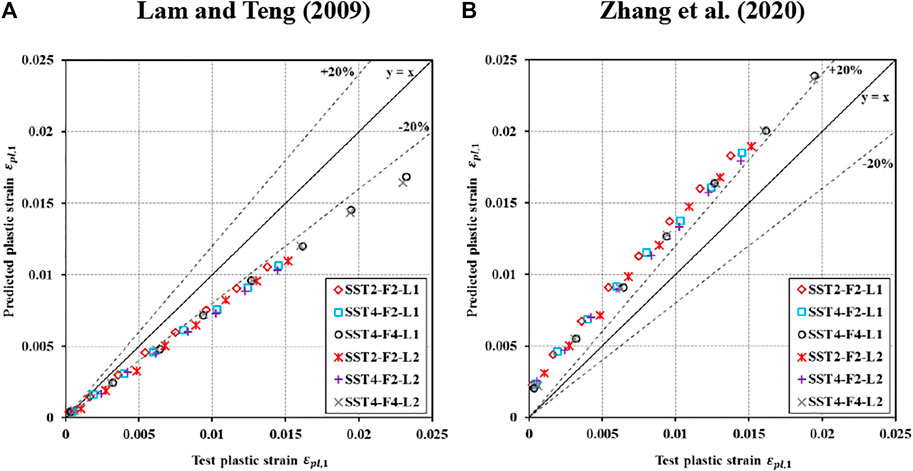
FIGURE 9. Assessment of the model predictions for
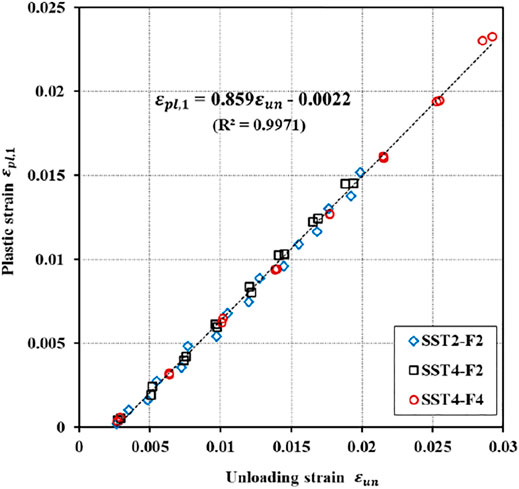
FIGURE 10. Relationship between
Strain Recovery Ratio
The strain recovery ratio
where
In Lam and Teng’s model (Lam and Teng, 2009),
where
The
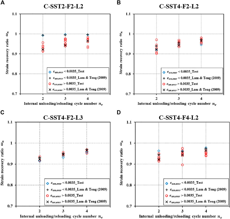
FIGURE 11. Comparisons of strain recovery ratios of internal cycles
Stress Deterioration Ratio
The new stress (
where
Lam and Teng (Lam and Teng, 2009) assumed that
where
Figure 12 plots the test

FIGURE 12. Comparisons of the stress deterioration factor of the first cycle
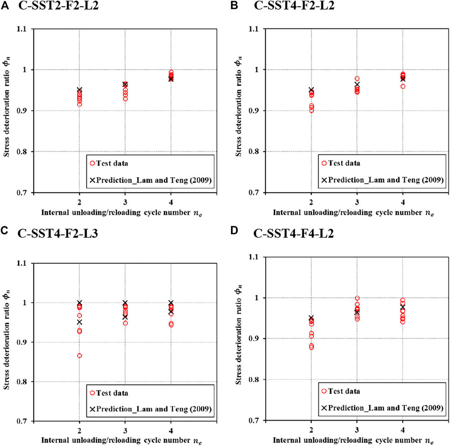
FIGURE 13. Comparisons of stress deterioration ratios of internal cycles
Conclusion
Axial compression tests were conducted on 22 F-SSCFSST and SSCFSST specimens in this study, including nine pairs (two identical specimens in a pair) under cyclic compression and four specimens under monotonic compression as references for those under cyclic compression. The effects of SST thickness, FRP thickness, and cyclic loading protocols are under investigation. The failure modes, axial load–strain behavior, and dilation behavior are presented. The applicability and accuracy of Lam and Teng’s model (Lam and Teng, 2009) were evaluated and discussed by analyzing three key parameters (plastic strain, strain recovery ratio, and stress deterioration ratio). The key findings are summarized below:
• SSCFSST specimens with no FRP confinement failed from elephant foot buckling at both loading ends, whereas F-SSCFSST specimens failed from SST local buckling and FRP rupture. FRP rupture was less fierce for F-SSCFSST specimens with repeated internal unloading/reloading cycles (L2 and L3) than for those with single unloading/reloading cycles (i.e., L1).
• The unloading curve in each cycle was a polynomial curve, while the curvature in the late unloading stage was not prominent due to the presence of SSTs. The reloading curve was almost a straight line before crossing the unloading strain, after which the reloading curve became curly and returned to the envelope curve. The plastic strain increased with more repeated internal unloading/reloading cycles.
• The axial load–strain curves of monotonic compression can be taken as the envelope curve for the cyclic responses as the differences were very small (less than 10%). Different cyclic loading protocols did not affect the ultimate load of a particular specimen obtained from monotonic compression. However, for a particular specimen, the ultimate axial strain of cyclic compression was 10–20% greater than that of monotonic compression.
• The confinement effect of the SST was weak; in comparison, increasing the FRP thickness can substantially restrain the dilations (and damages) of the concrete core. More dilations (and damages) were caused by the cyclic loading with repeated internal unloading/reloading cycles (L2 and L3).
• The envelope plastic strains
• Lam and Teng’s model (Lam and Teng, 2009) had satisfactory accuracy in predicting the strain recovery ratios
Data Availability Statement
The original contributions presented in the study are included in the article/Supplementary Material, further inquiries can be directed to the corresponding authors.
Author Contributions
J-JZ: conceptualization; funding acquisition; supervision; methodology; roles/writing—original draft; writing—review and editing. JL: investigation; data curation; roles/writing—original draft; formal analysis. W-FL: investigation and data curation. Y-CG: funding acquisition; project administration; and writing—review and editing. J-KZ: writing—review and editing. J-XL: writing—review and editing. KY: investigation and data curation.
Funding
The authors acknowledge the financial support received from the National Natural Science Foundation of China (Grant Nos. 51908137 and 52178277), the Natural Science Foundation of Guangdong Province (Grant Nos. 2019A1515011637 and 2021B1515020029), the Guangzhou Science, Technology, and Innovation Commission (2019040163), and the Guangdong Basic and Applied Basic Research Foundation (2019A1515110808).
Conflict of Interest
The authors declare that the research was conducted in the absence of any commercial or financial relationships that could be construed as a potential conflict of interest.
Publisher’s Note
All claims expressed in this article are solely those of the authors and do not necessarily represent those of their affiliated organizations, or those of the publisher, the editors, and the reviewers. Any product that may be evaluated in this article, or claim that may be made by its manufacturer, is not guaranteed or endorsed by the publisher.
References
ASTM A959 (2009). Standard Guide for Specifying Harmonized Standard Grade Compositions for Wrought Stainless Steels. Pennsylvania, USA: American Society for Testing Materials.
ASTM C469 and C469M-14 (2014). Standard Test Method for Static Modulus of Elasticity and Poisson Ratio of concrete in Compression. West Conshohocken, USA: ASTM.
ASTM D1141 (2013). Standard Practice for the Preparation of Substitute Ocean Water. West Conshohocken USA: ASTM International.
ASTM D3039/D3039M-17 (2014). Standard Test Method for Tensile Properties of Polymer Matrix Composite Materials. West Conshohocken, USA: ASTM.
Dai, P., Yang, L., Wang, J., and Zhou, Y. (2020). Compressive Strength of concrete-filled Stainless Steel Tube Stub Columns. Eng. Structures 205, 110106. doi:10.1016/j.engstruct.2019.110106
Ellobody, E., Young, B., and Lam, D. (2006). Behaviour of normal and High Strength concrete-filled Compact Steel Tube Circular Stub Columns. J. Constructional Steel Res. 62 (7), 706–715. doi:10.1016/j.jcsr.2005.11.002
Geng, Y., Wang, Y. Y., Chen, J., and Zhao, M. Z. (2020). Time-dependent Behaviour of 100% Recycled Coarse Aggregate concrete Filled Steel Tubes Subjected to High Sustained Load Level. Eng. Struct. 210, 110353.
Gholampour, A., and Ozbakkaloglu, T. (2018). Behavior of Steel Fiber-Reinforced concrete-filled FRP Tube Columns: Experimental Results and a Finite Element Model. Compos. Structures 194, 252–262. doi:10.1016/j.compstruct.2018.03.094
Guo, L., Liu, Y., Fu, F., and Huang, H. (2019). Behavior of Axially Loaded Circular Stainless Steel Tube Confined concrete Stub Columns. Thin-Walled Structures 139, 66–76. doi:10.1016/j.tws.2019.02.014
Han, L.-H., Xu, C.-Y., and Tao, Z. (2019). Performance of concrete Filled Stainless Steel Tubular (CFSST) Columns and Joints: Summary of Recent Research. J. Constructional Steel Res. 152, 117–131. doi:10.1016/j.jcsr.2018.02.038
Hou, C., Han, L.-H., and Zhao, X.-L. (2014). Concrete-filled Circular Steel Tubes Subjected to Local Bearing Force: Finite Element Analysis. Thin-Walled Structures 77, 109–119. doi:10.1016/j.tws.2013.12.006
Lam, L., Teng, J. G., Cheung, C. H., and Xiao, Y. (2006). FRP-confined concrete under Axial Cyclic Compression. Cement and Concrete Composites 28 (10), 949–958. doi:10.1016/j.cemconcomp.2006.07.007
Lam, L., and Teng, J. G. J. G. (2009). Stress-strain Model for FRP-Confined concrete under Cyclic Axial Compression. Eng. Structures 31, 308–321. doi:10.1016/j.engstruct.2008.08.014
Li, P., and Wu, Y.-F. (2015). Stress-strain Model of FRP Confined concrete under Cyclic Loading. Compos. Structures 134, 60–71. doi:10.1016/j.compstruct.2015.08.056
Liao, J. J., Li, Y. L., Ouyang, Y., and Zeng, J. J. (2021). Axial Compression Tests on Elliptical High Strength Steel Tubes Filled with Self-Compacting concrete of Different Mix Proportions. J. Build Eng. 40, 1026788. doi:10.1016/j.jobe.2021.102678
Liao, J. J., and Ma, G. (2018). Energy Absorption of the Ring Stiffened Tubes and the Application in Blast wall Design. Struct. Eng. Mech. 66 (6), 713–727.
Liao, J., and Ma, G. (2018). The Blast Alleviation Effects of a Hybrid Barrier System with Triple Energy Absorbers. Mar. Structures 61, 540–559. doi:10.1016/j.marstruc.2018.06.018
Liao, J., Yang, K. Y., Zeng, J.-J., Quach, W.-M., Ye, Y.-Y., and Zhang, L. (2021). Compressive Behavior of FRP-Confined Ultra-high Performance concrete (UHPC) in Circular Columns. Eng. Structures 249, 113246. doi:10.1016/j.engstruct.2021.113246
Liao, J., Zeng, J.-J., Bai, Y.-L., and Zhang, L. (2022a). Bond Strength of GFRP Bars to High Strength and Ultra-high Strength Fiber Reinforced Seawater Sea-Sand concrete (SSC). Compos. Structures 281, 115013. doi:10.1016/j.compstruct.2021.115013
Liao, J., Zeng, J.-J., Gong, Q.-M., Quach, W.-M., Gao, W.-Y., and Zhang, L. (2022b). Design-oriented Stress-Strain Model for FRP-Confined Ultra-high Performance concrete (UHPC). Construction Building Mater. 318, 126200. doi:10.1016/j.conbuildmat.2021.126200
Mo, X.-D., Zeng, W.-Q., Liao, J., and Zeng, J.-J. (2022). Flexural Behavior of Hybrid FRP-concrete-steel Double-Skin Tubular Beams with PBL Shear Connectors. Eng. Structures 254, 113840. doi:10.1016/j.engstruct.2022.113840
Ouyang, Y., Zeng, J., Li, L., and Kwan, A. (2020). Influence of concrete Mix Proportions on Axial Performance of concrete-filled Steel Tubes Made with Self-Compacting concrete. Adv. Struct. Eng. 23 (5), 835–846. doi:10.1177/1369433219884457
Ozbakkaloglu, T., and Akin, E. (2011). Behavior of FRP-Confined normal- and High-Strength concrete under Cyclic Axial Compression. J. Compos. Construct 16, 451–463.
Pan, B., Liu, F., Zhuge, Y., Zeng, J.-J., and Liao, J. (2022). ECCs/UHPFRCCs with and without FRP Reinforcement for Structural Strengthening/repairing: A State-Of-The-Art Review. Construction Building Mater. 316, 125824. doi:10.1016/j.conbuildmat.2021.125824
Qiao, Q., Yang, Z., and Cao, W. (2021). Axial Compressive Behavior of Stainless Steel Tube Confined concrete Column Piers. Mar. Struct. 78, 103021.
Tan, Q.-H., Gardner, L., Han, L.-H., and Song, T.-Y. (2020). Performance of concrete-filled Stainless Steel Tubular (CFSST) Columns after Exposure to Fire. Thin-Walled Structures 149, 106629. doi:10.1016/j.tws.2020.106629
Tang, H., Chen, J., Fan, L., Sun, X., and Peng, C. (2020). Experimental Investigation of FRP-Confined concrete-filled Stainless Steel Tube Stub Columns under Axial Compression. Thin-Walled Structures 146, 106483. doi:10.1016/j.tws.2019.106483
Tao, Z., Han, L.-H., and Zhuang, J.-P. (2007). Axial Loading Behavior of CFRP Strengthened Concrete-Filled Steel Tubular Stub Columns. Adv. Struct. Eng. 10, 37–46. doi:10.1260/136943307780150814
Teng, J. G., Hu, Y. M., and Yu, T. (2013). Stress-strain Model for concrete in FRP-Confined Steel Tubular Columns. Eng. Structures 49, 156–167. doi:10.1016/j.engstruct.2012.11.001
Wang, W., Sheikh, M. N., Al-Baali, A. Q., and Hadi, M. N. S. (2018). Compressive Behaviour of Partially FRP Confined concrete: Experimental Observations and Assessment of the Stress-Strain Models. Construction Building Mater. 192, 785–797. doi:10.1016/j.conbuildmat.2018.10.105
Wang, Y. H., Nie, J. G., and Fan, J. S. (2013). Theoretical Model and Investigation of concrete Filled Steel Tube Columns under Axial Force–Torsion Combined Action. Thin-walled Struct. 69, 1–9.
Wang, Z.-B., Tao, Z., Han, L.-H., Uy, B., Lam, D., and Kang, W.-H. (2017). Strength, Stiffness and Ductility of concrete-filled Steel Columns under Axial Compression. Eng. Structures 135, 209–221. doi:10.1016/j.engstruct.2016.12.049
Wei, Y., Bai, J., Zhang, Y., Miao, K., and Zheng, K. (2021). Compressive Performance of High-Strength Seawater and Sea-Sand concrete-filled Circular FRP-Steel Composite Tube Columns. Eng. Structures 240 (8), 112357. doi:10.1016/j.engstruct.2021.112357
Wei, Y., Jiang, C., and Wu, Y.-F. (2019). Confinement Effectiveness of Circular concrete-filled Steel Tubular Columns under Axial Compression. J. Constructional Steel Res. 158 (7), 15–27. doi:10.1016/j.jcsr.2019.03.012
Wei, Y., Zhang, Y., Chai, J., Wu, G., and Dong, Z. (2020). Experimental Investigation of Rectangular concrete-filled Fiber Reinforced Polymer (FRP)-steel Composite Tube Columns for Various Corner Radii. Compos. Structures 244, 112311. doi:10.1016/j.compstruct.2020.112311
Wu, Y.-F., and Jiang, C. (2013). Effect of Load Eccentricity on the Stress-Strain Relationship of FRP-Confined concrete Columns. Compos. Structures 98, 228–241. doi:10.1016/j.compstruct.2012.11.023
Xiao, Y., He, W., and Choi, K.-k. (2005). Confined concrete-filled Tubular Columns. J. Struct. Eng. 131 (3), 488–497. doi:10.1061/(asce)0733-9445(2005)131:3(488)
Xiong, M.-X., Xiong, D.-X., and Liew, J. Y. R. (2017). Axial Performance of Short concrete Filled Steel Tubes with High- and Ultra-high- Strength Materials. Eng. Structures 136, 494–510. doi:10.1016/j.engstruct.2017.01.037
Ye, Y.-Y., Liang, S.-D., Feng, P., and Zeng, J.-J. (2021). Recyclable LRS FRP Composites for Engineering Structures: Current Status and Future Opportunities. Composites B: Eng. 212, 108689. doi:10.1016/j.compositesb.2021.108689
Yu, T., Hu, Y. M., and Teng, J. G. (2014). FRP-confined Circular concrete-filled Steel Tubular Columns under Cyclic Axial Compression. J. Constructional Steel Res. 94, 33–48. doi:10.1016/j.jcsr.2013.11.003
Zeng, J.-J., Duan, Z.-J., Gao, W.-Y., Bai, Y.-L., and Ouyang, L.-J. (2020a). Compressive Behavior of FRP-Wrapped Seawater Sea-Sand concrete with a Square Cross-Section. Construction Building Mater. 262, 120881. doi:10.1016/j.conbuildmat.2020.120881
Zeng, J.-J., Gao, W.-Y., Duan, Z.-J., Bai, Y.-L., Guo, Y.-C., and Ouyang, L.-J. (2020b). Axial Compressive Behavior of Polyethylene Terephthalate/carbon FRP-Confined Seawater Sea-Sand concrete in Circular Columns. Construction Building Mater. 234, 117383. doi:10.1016/j.conbuildmat.2019.117383
Zeng, J.-J., Liang, S.-D., Li, Y.-L., Guo, Y.-C., and Shan, G.-Y. (2021a). Compressive Behavior of FRP-Confined Elliptical concrete-filled High-Strength Steel Tube Columns. Compos. Structures 266, 113808. doi:10.1016/j.compstruct.2021.113808
Zeng, J.-J., Liao, J., Ye, Y.-Y., Guo, Y.-C., Zheng, Y., and Tan, L.-H. (2021b). Behavior of FRP Spiral Strip-Confined concrete under Cyclic Axial Compression. Construction Building Mater. 295, 123544. doi:10.1016/j.conbuildmat.2021.123544
Zeng, J.-J., Liao, J., Zhuge, Y., Guo, Y.-C., Zhou, J.-K., Huang, Z.-H., et al. (2022a). Bond Behavior between GFRP Bars and Seawater Sea-Sand Fiber-Reinforced Ultra-high Strength concrete. Eng. Structures 254, 113787. doi:10.1016/j.engstruct.2021.113787
Zeng, J.-J., Ye, Y.-Y., Guo, Y.-C., Lv, J.-F., Ouyang, Y., and Jiang, C. (2020c). PET FRP-concrete-high Strength Steel Hybrid Solid Columns with Strain-Hardening and Ductile Performance: Cyclic Axial Compressive Behavior. Composites Part B: Eng. 190, 107903. doi:10.1016/j.compositesb.2020.107903
Zeng, J.-J., Ye, Y.-Y., Quach, W.-M., Lin, G., Zhuge, Y., and Zhou, J.-K. (2022b). Compressive and Transverse Shear Behaviour of Novel FRP-UHPC Hybrid Bars. Compos. Structures 281, 115001. doi:10.1016/j.compstruct.2021.115001
Zeng, J. J., Zheng, Y. W., Liu, F., Guo, Y. C., and Hou, C. (2020d). Behavior of FRP Ring-Confined CFST Columns under Axial Compression. Compos. Struct. 257, 113166.
Zhang, Y., Wei, Y., Bai, J., Wu, G., and Dong, Z. (2020). A Novel Seawater and Sea-Sand concrete Filled FRP-Carbon Steel Composite Tube Column: Concept and Behaviour. Compos. Structures 246, 112421. doi:10.1016/j.compstruct.2020.112421
Zhang, Y., Wei, Y., Bai, J., and Zhang, Y. (2019). Stress-strain Model of an FRP-Confined concrete Filled Steel Tube under Axial Compression. Thin-Walled Structures 142, 149–159. doi:10.1016/j.tws.2019.05.009
Zhang, Y., Wei, Y., Zhao, K., Ding, M., and Wang, L. (2020). Analytical Model of concrete-filled FRP-Steel Composite Tube Columns under Cyclic Axial Compression. Soil Dyn. Earthquake Eng. 139, 106414. doi:10.1016/j.soildyn.2020.106414
Keywords: fiber-reinforced polymer (FRP), seawater sea-sand concrete (SSC), stainless steel tube (SST), axial cyclic compression, plastic strain
Citation: Zeng J-J, Liao J, Liang W-F, Guo Y-C, Zhou J-K, Lin J-X and Yan K (2022) Cyclic Axial Compression Behavior of FRP-Confined Seawater Sea-Sand Concrete-Filled Stainless Steel Tube Stub Columns. Front. Mater. 9:872055. doi: 10.3389/fmats.2022.872055
Received: 09 February 2022; Accepted: 23 February 2022;
Published: 23 March 2022.
Edited by:
Xiaoshan Lin, RMIT University, AustraliaReviewed by:
Yang Wei, Nanjing Forestry University, ChinaYulei Bai, Beijing University of Technology, China
Copyright © 2022 Zeng, Liao, Liang, Guo, Zhou, Lin and Yan. This is an open-access article distributed under the terms of the Creative Commons Attribution License (CC BY). The use, distribution or reproduction in other forums is permitted, provided the original author(s) and the copyright owner(s) are credited and that the original publication in this journal is cited, in accordance with accepted academic practice. No use, distribution or reproduction is permitted which does not comply with these terms.
*Correspondence: Jun-Jie Zeng, amp6ZW5nQGdkdXQuZWR1LmNu; Yong-Chang Guo, Z3VveWNAZ2R1dC5lZHUuY24=