- 1School of Civil Engineering, University of Science and Technology Liaoning, Anshan, China
- 2School of Mechatronic Engineering, Southwest Petroleum University, Chengdu, China
In order to study the compressive torsional behavior of concrete-filled CFRP steel tubes (CF-CFRP-STs), the static test of eight circular section CF-CFRP-ST compression torsional specimens was carried out. The characteristics of the torque–angle (T–θ) curve and shear stress shear–strain (τ–γ) curve, failure mode, cooperative work between steel tubes and CFRP, and cross-section assumption were studied. The T–θ curve, τ–γ curve, and failure mode of the specimen are simulated by ABAQUS. Based on the above research, the stress distribution of each component material is analyzed. The effects of transverse CFRP layers, material strength, steel ratio, and axial compression ratio on the static performance of members are discussed. Based on the performance analysis, the bearing capacity equation of CF-CFRP-ST compression-torsional members is proposed.
Introduction
In recent years, with the reduction of cost, carbon fiber has also been widely used in the construction engineering industry (Chen et al., 2018). As a derivative of carbon fiber, carbon fiber polymer reinforcement (CFRP) is often used in the reinforcement of building structures (Liang et al., 2021). Concrete-filled steel tubes (CFSTs) have the advantages of high bearing capacity and convenient construction. At present, it is widely used in the field of construction engineering (Hu and Han, 2016; Ye et al., 2016), but its own defects cannot be ignored, especially local buckling under load and corrosion in the marine environment (Hua et al., 2015). Based on this, a new composite structure of CFRP concrete-filled steel tubes is proposed; it fully combines the advantages of concrete-filled steel tubes and CFRP so that compared with the traditional CFST structure, it has the advantages of delaying structural buckling and improving the synergy between concrete and steel tubes (Li et al., 2018; Zhang et al., 2020).
Nie et al. (2013) conducted a study on the flexural–shear–torsion coupling bearing capacity of concrete-filled steel tubular short columns and concluded that the failure mechanism of concrete-filled steel tubular short columns was significantly affected by the bending moment–torque ratio. Zhang et al. (2019) carried out axial compression test research on eight concrete-filled steel tubular short columns strengthened with CFRP with spherical crown void defects. Chen et al. (2018) carried out the axial compression test of square concrete-filled steel tubular short columns after CFRP restraint heating. Based on the regression of test data, a simplified formula for the ultimate strength of concrete-filled square steel tubular short columns after CFRP confined heating is proposed. Tang et al. (2020) studied the axial compressive bearing capacity of CFRP concrete-filled steel tubes, with a total of 24 short columns. Sundarraja and Ganesh Prabhu (2011) studied the strengthening effect of CFRP on concrete-filled steel tubular flexural members. Romero et al. (2020) carried out experimental research and finite element theoretical analysis on the fire performance of concrete-filled steel tubular members. The results show that the steel tube and CFRP can work together, and the deformation of the component approximately conforms to the plane section assumption. Han and Zhong (2004) deduced the axial force–torque correlation equation of concrete-filled steel tubular members, described the moment torque correlation equation, and analyzed the whole process of such specimens. Nie et al. (2014a) conducted an experimental study on the torsional hysteretic behavior of concrete-filled steel tubes with circular sections and rectangular sections. The results show that the hysteretic curve is very full, the unloading stiffness and the initial loading stiffness of the specimen are almost the same, and the specimen shows good energy dissipation performance; the torsion resistance of the specimen with too large axial compression ratio is weakened due to too serious deformation. Zhou et al. (2017) carried out the pure torsional hysteretic behavior test of hollow sandwich concrete-filled steel tubular specimens with section form and void ratio as the main parameters. The experimental results show that the initial elastic stiffness is close to the unloading stiffness, the specimens show good energy dissipation capacity, and the hysteretic behavior of circular section hollow sandwich concrete-filled steel tubes is better than that of square section (Nie, 2005; Nie et al., 2014b). Sundarraja and Ganesh (Park, 2010) found that the steel ratio and the number of CFRP layers have great influence on the bearing capacity of square CFRP-CFST specimens and proposed a finite element simulation method to reproduce the mechanical behavior of square CFRP-CFST effectively. Tao et al. (2007a; Sundarraja and Ganesh, 2011) indicated that the bearing capacity of CFRP-CFST specimens was significantly reduced after the fire, but the fire resistance ability of concrete-filled CFRP-steel tubular specimens was better than that of ordinary concrete-filled steel tubular specimens. Wang and Shao (Tao et al., 2007b) studied the influence of various materials on the bearing capacity of square concrete-filled CFRP-steel tubes under axial compression.
However, most of these were mainly focused on the compressive and flexural performances of the composite members. In practice, CF-CFRP-ST often also bears coupling loads, such as fans and other building structures. In view of this, eight specimens were designed. During the loading of the test, the effects of the axial compression ratio and a number of longitudinal CFRP layers were studied under compression torsion load. Based on experimental research, a finite element method for establishing CF-CFRP-ST compression–torsion member is proposed by finite element simulation. The influence of main parameters on performance is studied by this method so as to provide a bearing capacity correlation equation for engineering practice.
Experimental Study of CF-CFRP-ST Under Compression–Torsion Load
Design of Specimens and Performance of Material
Design of Specimens
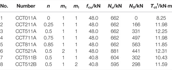
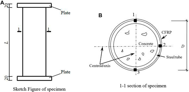
A total of eight compression-torsional static performance tests of circular concrete-filled CFRP steel tubes were designed, and the main parameters include n, mt, ml, and fcu. L of all specimens is 342 mm, the wall thickness (ts) is 1.6 mm, and Ds is 114 mm. Nu is the axial compression bearing capacity of the C-CF-CFRP-ST specimen. N0 is the axial force under specimens in the test. Tctt is the torque applied during the test. All parameters are shown in Table 1. A schematic diagram of the C-CF-CFRP-ST specimen is shown in Figure 1.
Performance of Material
The measured material properties of steel tubes are shown in Table 2, and the performance of concrete in the test is shown in Table 3.
Carbon fiber fabric is a unidirectional fabric woven by Toray T700 12 K carbon fiber in Japan. The thickness of the single layer and the weight of CFRP are 0.111 mm and 200 g/m3, respectively. The elongation at break of CFRP is 2.1%, and the tensile strength of monofilament is 4.9 GPA. εcftr and εcflr are the fracture strains of CFRP in the transverse and longitudinal directions, respectively, Mechanical property of CFRP is shown in Table 4.
Loading and Measurement
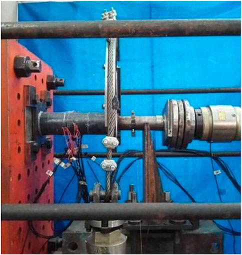
The loading equipment of CFRP concrete-filled steel tubes under compression–torsion specimens is shown in Figure 2. The end plate fixing device is connected at one end to avoid the relative displacement between the end plate and the reaction wall or the force arm, and the force arm is connected at the other end to apply torque. In addition, a jack is added to apply axial force. The graded loading system is adopted in the test. Within the elastic range, the loading amount of each level is 1/10 of the estimated bearing capacity, and the next level of loading is carried out after holding the load for 2 min. When the torque reaches about 60% of the estimated bearing capacity, the continuous slow loading mode shall be adopted until the jack range is reached, and the test shall be stopped. The estimation method of bearing capacity is as follows: according to the principle of equal strength, all CFRPs are quantified as steel tubes, and then the bearing capacity is calculated according to the relevant calculation formula (Hou et al., 2016) of torsional bearing capacity of concrete-filled steel tubes. Figure 3 shows all compression torsion test pieces before loading.
Experimental Phenomenon
Partial circular compression torsion specimen after loading is shown in Figure 4. At the beginning of loading, the torque and rotation angle are linear, and the appearance of the specimen has no obvious change. As the torque increases, a slight adhesive cracking sound can be heard, and the axial compression ratio has a significant impact on the test phenomenon. For the specimen with n = 0, CFRP breaks continuously with the continuous increase of torque. For specimens with n > 0, CFRP begins to fracture when the torque reaches about 70% of the peak torque. When the torque reaches about 80–90% of the peak torque, local convex bending appears in the middle section and its nearby position of the specimen. With the continuous increase of torque, a large number of CFRPs in the middle section fracture. After reaching the peak torque, the specimens continue to deform and the bearing capacity decreases. During the loading process, the longitudinal CFRP does not break.
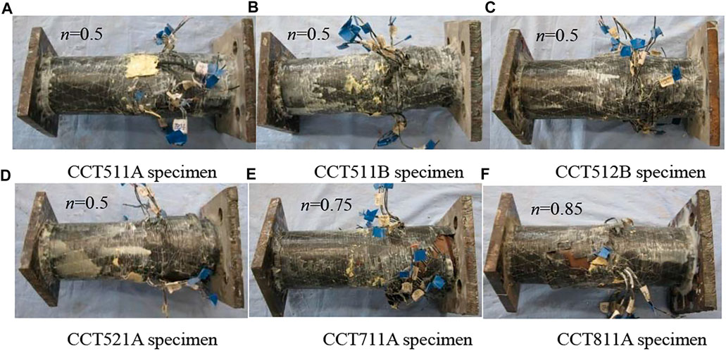
FIGURE 4. Partial circular compression torsion specimen after loading. (A–F) Different axial compression ratio for those specimen.
When the steel tube loaded with the test piece is cut open, it can be seen that when the axial compression ratio is small, a large number of inclined cracks in the direction of 30°–45° appear on the surface of the concrete [Figure 5A]. When the axial compression ratio is large, the cracks are more obvious and the concrete is crushed. Since CFRP steel tubes provide good constraints on concrete, the convex of concrete is consistent with that of steel tubes [Figure 5B], and the concrete shows good plastic filling performance.
Experimental Results
T–θ Curves
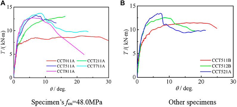
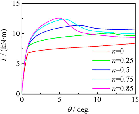
Figure 6 shows the T–θ curve of the circular compression torsion specimen. It can be seen that at the initial stage of loading, the curve is in the elastic stage, and the torque has a linear relationship with the rotation angle. When the angle is about 8°, the growth rate of the angle exceeds the torque, and the curve enters the strengthening stage. As loading continues, the axial compression ratio has a significant impact on the curve. When n = 0, there is no steep drop section in the curve. When 0.25 ≤ n ≤ 0.75, the peak torque increases with the increase of the axial compression ratio, and in the falling section, the speed of torque increases with the increase of the axial compression ratio; when n = 0.85, the peak torque decreases compared with n = 0.75, and the torque decreases faster in the descending section. Since concrete is the main component of the specimen, improving the strength of concrete can significantly improve the bearing capacity of the specimen.
τ–γ Curves
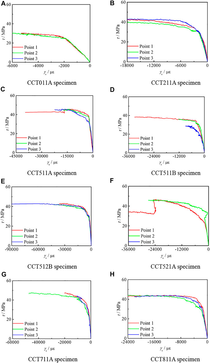
Figure 7 shows the τ–γ curve of circular compression torsion specimens, where γ = 2εs45−(εst+εsl).
It can be seen that at the initial stage of loading, the curve develops linearly, belonging to the elastic stage. With the increase of torque, the shear stress increases, and the shear strain increases slowly. It is indicated that the shear capacity of the specimen is good. When the torque reaches about 70–80% of the peak torque, the shear strain continues to increase and the torque remains basically unchanged. In the later stage of loading, the curve has no descending section and gradually tends to be gentle. The shear stress increases slightly, and the shear strain increases significantly.
Cooperation Between Steel Tube and CFRP
Figures 8–10,, are the T-εt, T-εl, and T-ε45 curves of compression torsion specimens, respectively. It can be seen that εst and εcft are basically the same, and steel pipe and CFRP can work together. Also, εs45 is always negative and εst is always positive. For εsl, when n ≤ 0.25, εsl is positive. When n ≥ 0.75, εsl is negative. When n = 0.5, εsl is either positive or negative.
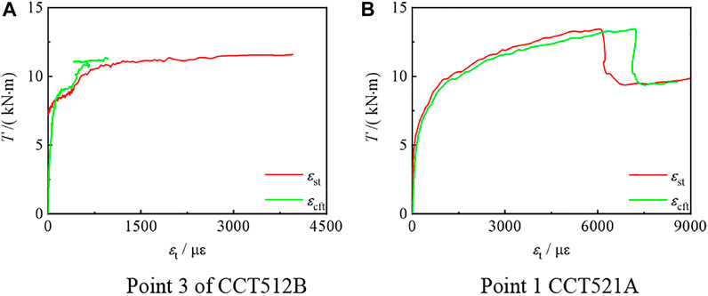
FIGURE 8. T–εt curve of the partial C-CF-CFRP-ST specimen. (A) Transverse strain of steel tube and (B) CFRP.
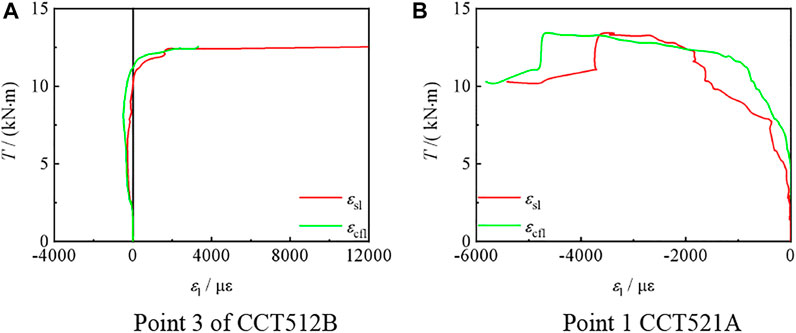
FIGURE 9. T–εl curve of the partial C-CF-CFRP-ST specimen. (A) Longitudinal strain of steel tube and (B) CFRP.
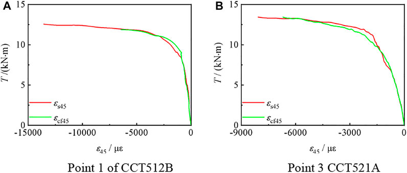
FIGURE 10. T–ε45 curve of the partial C-CF-CFRP-ST specimen. (A) 45° strain of steel tube and (B) CFRP.
Finite Element Study of CF-CFRP-ST Under Compression–Torsion Load
Stress–Strain Relationship of Materials
In the process of using ABAQUS finite element modeling, the steel tube adopts the mixed hardening model provided by ABAQUS software and concrete adopts the plastic damage model provided by ABAQUS finite element software. To further analyze the mechanical behavior of C-CF-CFRP-ST specimens under eccentric load comprehensively, finite element models are established and analyzed in this study. The details of the stress–strain relationships of the steel are used according to the constitutive model suggested by Wang et al. (Wang and Shao, 2014).
The confinement of transverse CFRP is quantified by the confinement factor of transverse CFRP (ξcf) (Wang et al., 2015). The reinforcement efficiency of longitudinal CFRP is defined as a strengthening coefficient (η) (Tao et al., 2008; Wang et al., 2017). All influence factors are given from Eqs 1–3.
where Acft and fcft are the cross-sectional area and the ultimate tensile strength of the transverse CFRP, respectively. Acfl and fcfl are the cross-sectional area and the ultimate tensile strength of the longitudinal CFRP, respectively (.
When the strain of transverse CFRP reaches its fracture strain εcftr (5500 με) or the strain of longitudinal CFRP reaches its fracture strain εcflr (7000 με), the transverse restraint effect or longitudinal reinforcement effect on the steel pipe will be lost.
Element Selection and Boundary Conditions
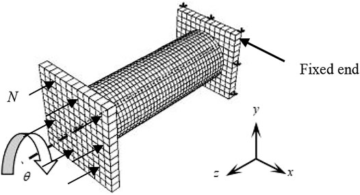
In the finite element simulation, the three-dimensional solid element C3D8R is used to simulate steel pipe, concrete, and end plate, and the M3D4R element is used to simulate CFRP. The full model calculation is adopted, one end adopts completely fixed boundary conditions, and the other end applies rotation angle on the reference point. One side is used as the fixed end to restrict the displacement and rotation angle in x, y, and z directions; as the loading end, first apply the same axial force N on the end plate as in the test, and N is always constant during the whole loading process. Then set a reference point in the center of the end plate and connect it with the loading end plate, and then apply a rotation angle θ on the reference point. Figure 11 is Boundary conditions for finite element simulation of specimens. Figure 12 is Grid generation of all materials.
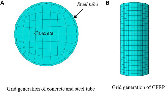
FIGURE 12. Grid generation of all materials. (A) Grid generation of concrete and steel tube(B) Grid generation of CFRP.
Comparison Between Simulation Results and Test Results
Figure 13 shows the comparison between the simulation results of the T–θ curve of the circular compression–torsion specimen and the test results. It can be seen that the simulation results are basically consistent with the experimental results.
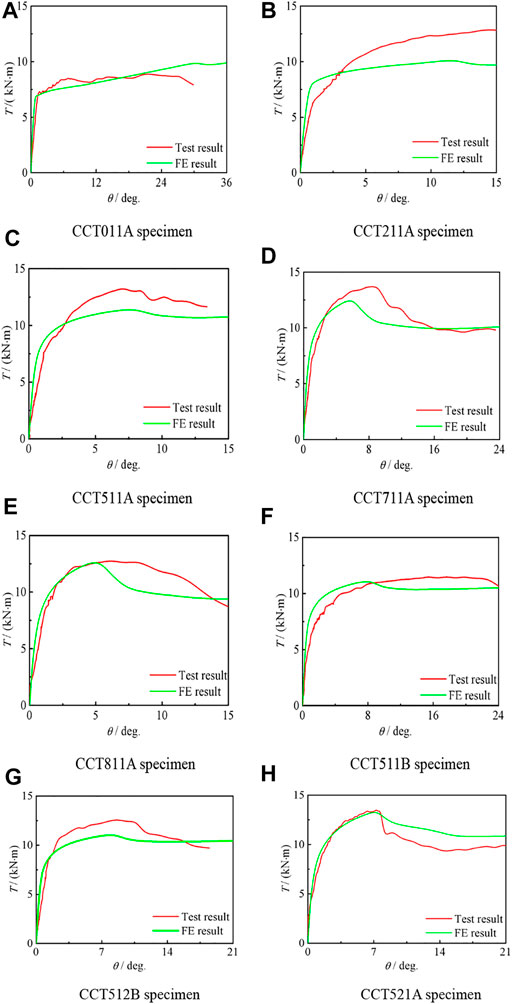
FIGURE 13. Comparison between T–θ curve simulation results and test results of compression torsion specimens. (A–H)Different curves between Test and FE result.
Figure 14 shows the comparison between the simulation results of the τ–γ curve of the circular compression–torsion specimen and the test results. It can be seen that the simulation results are basically consistent with the experimental results.
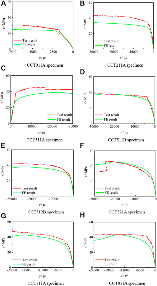
FIGURE 14. Comparison between τ–γ curve simulation results and test results of compression torsion specimens. (A–H) Different curves between Test and FE result.
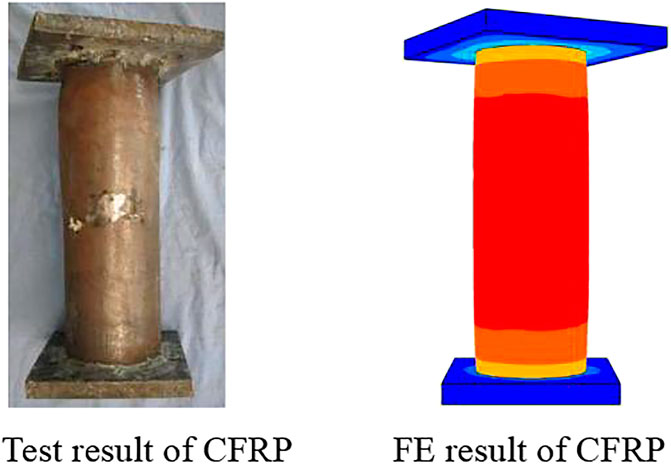
Figure 15 shows the failure mode of CFRP. It can be seen that the fracture of transverse CFRP in the test results and simulation results are basically the same.
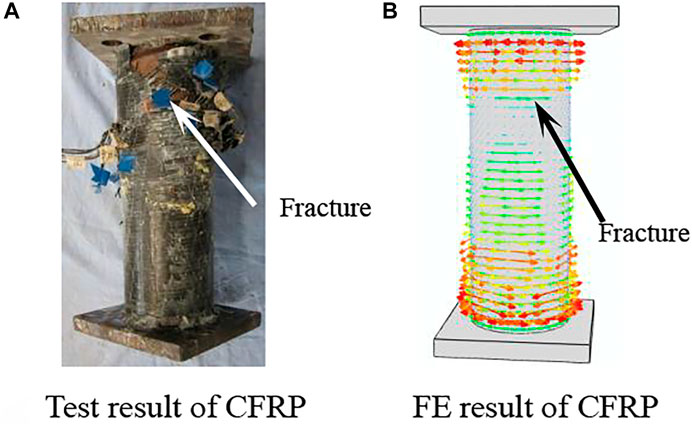
FIGURE 15. Failure mode of CFRP of the compression torsion specimen. (A) Test results of CFRP, (B) FE results of CFRP.
Figure 16 shows the failure mode of the steel tube. It can be seen that the specimen is twisted, and the stress is mainly concentrated in the middle.
Figure 17 shows the failure mode of concrete. The results of finite element simulation show that the crack mainly extends from the middle of the specimen, which is basically consistent with the test results. In conclusion, the failure modes of CFRP, steel tube, and concrete are compared, respectively, and the finite element is basically consistent with the test results.
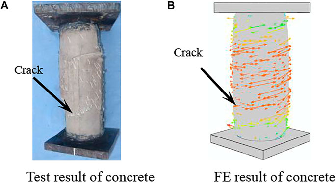
FIGURE 17. Failure mode of concrete of the compression torsion specimen. (A) Test results of concrete, (B) FE results of concrete.
Analysis of the Whole Process of Stress
Typical Torque Angle Curve
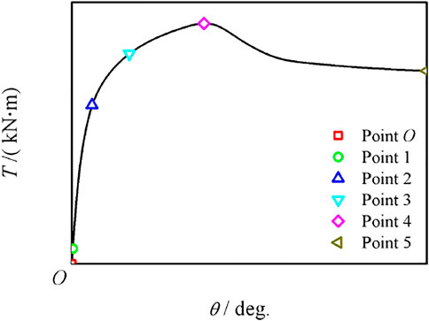
Figure 18 shows the typical T–θ curve of CFRP concrete-filled steel tubular compression torsion members. The curve is divided into three stages and five feature points are selected. In the elastic stage (point O ∼ point 2), the torque is basically linear with the rotation angle. Due to the action of axial force, point 1 corresponds to the steel entering the yield state, and point 2 corresponds to the cracks in the concrete; in the elastic–plastic stage (2–3 points), with the gradual increase of torque, the steel pipe and concrete are in a two-way shear state and produce an interaction force, and the three points correspond to the transverse CFRP fracture; in the plastic strengthening stage (3–5 points), the cracks in the concrete continue to develop, and some of the concrete quit work. However, due to the constraint of the outer pipe on the concrete, the bearing capacity continues to increase, and the torsional bearing capacity is reached at four points. After four points, the curve enters the descending section first, and the bearing capacity gradually decreases. In the later stage of loading, the bearing capacity increases slightly, and the corresponding rotation angle at five points reaches 15°. During the loading process, the longitudinal CFRP was not fractured.
Through three stages are Elastic stage, elastoplastic stage and plastic stage and five characteristic points to analyze its working mechanism in the whole stress process. Calculation parameters include L = 342 mm, Ds = 114 mm, ts = 1.6 mm, fcu = 48 mpa, Ec = 4700 f 'c0.5(f 'c = 42 MPa), fy = 290.8 MPa, ξs = 0.530, ξcf = 0.162, and n = 0.75.
Interaction Between Steel Tube and Concrete
Figure 19 shows the distribution of interaction force between the steel tube and concrete in compression torsion member. It can be seen that at point O, the member deformation is small. With the gradual increase of member deformation, the interaction force of members increases. During the loading process, the interaction force of members is evenly distributed on the concrete surface. Due to the action of axial force, the interaction force between the end plate and concrete end is greater than that between the steel tube and concrete.
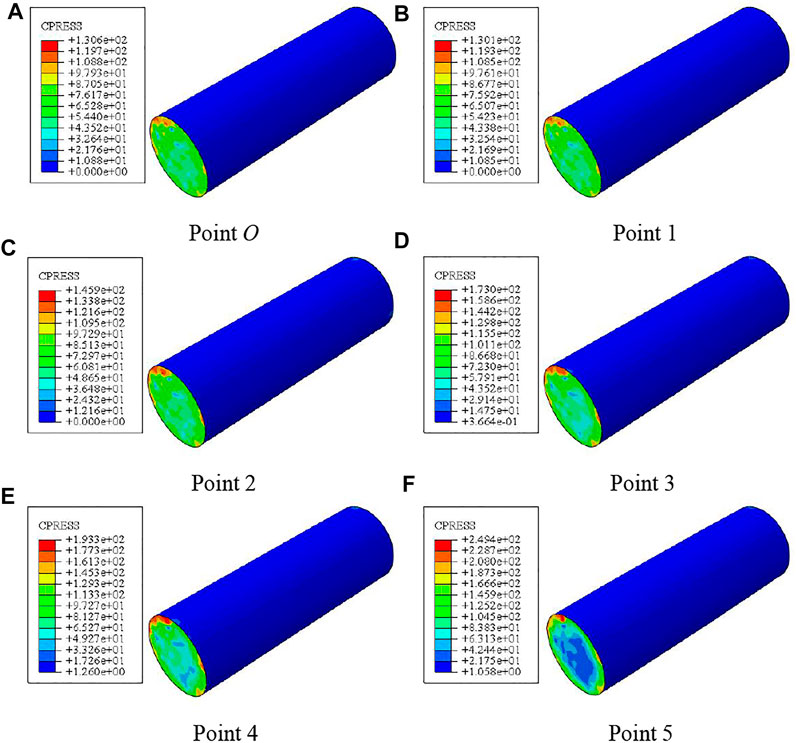
FIGURE 19. Distribution of interaction force between the steel tube and concrete. (A–F) Crack of Distribution of interaction force between the steel tube and concrete at different 0–5 points.
Shear Stress Distribution of Concrete
Figure 20 shows the shear stress distribution of the section concrete in the compression torsion member. It can be seen that the shear stress of the member first increases and then decreases. At point four, the shear stress reaches its peak, about 26 MPa. During the loading process, the shear stress is roughly antisymmetric distribution on the section, and the stress contour always follows “U”-shaped distribution.
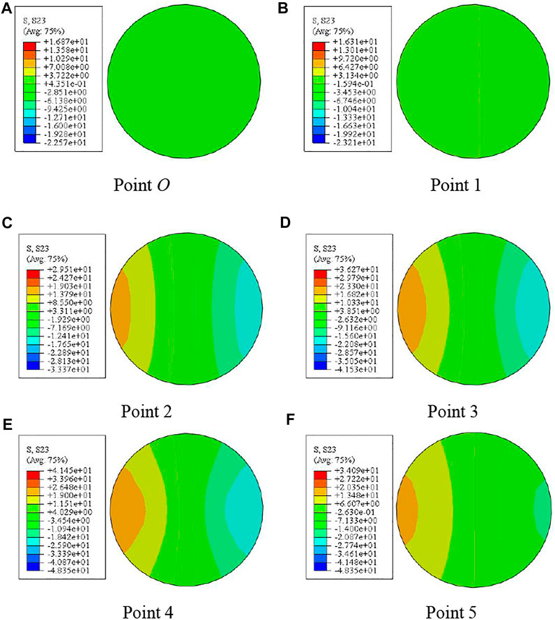
FIGURE 20. Shear stress distribution of the section concrete. (A–F) crack of Shear stress distribution of the section concrete at different 0–5 points.
Mises Stress of Steel Tube
Figure 21 shows the Mises stress distribution of the compression torsion member steel tube. In the loading process, the steel tube quickly reaches the yield strength; that is, at pointone, the Mises stress of the steel pipe is about 291 MPa, and the steel enters the yield state. Under the action of torque, the Mises stress of the section in the steel changes little.
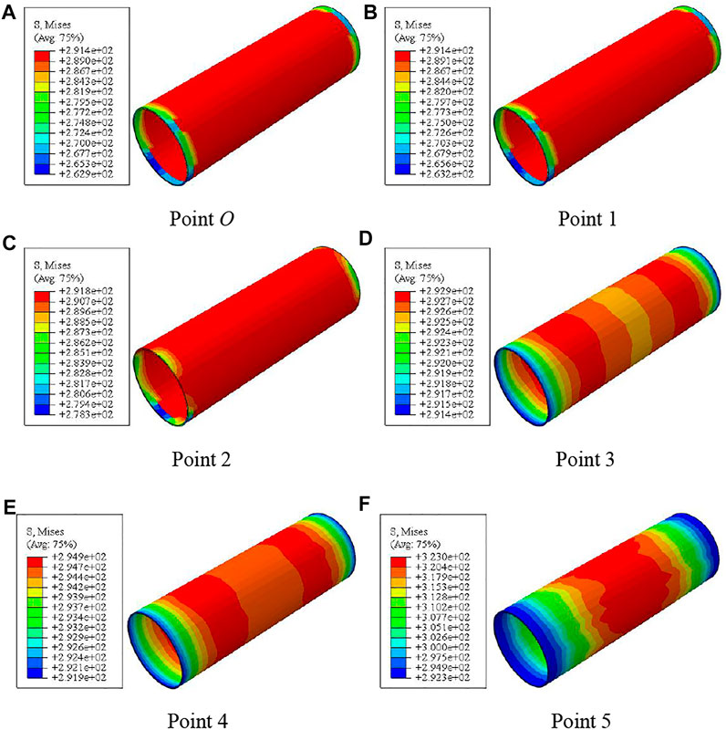
FIGURE 21. Mises distribution of the steel tube. (A–F) Mises distribution of the steel tube at different 0–5 points.
Stress of CFRP
Figure 22 shows the stress distribution of transverse CFRP of compression torsion members. It can be seen that at the initial stage of loading, the stress growth rate of transverse CFRP is slow. In the process of loading to point two, the stress of transverse CFRP increases gradually; at point three, the transverse CFRP stress of the member is about 1265 MPa and the corresponding strain is about 5500 με, at this time, the transverse CFRP is broken. After loading to point four, the fracture area of transverse CFRP gradually increases from the middle section to the end.
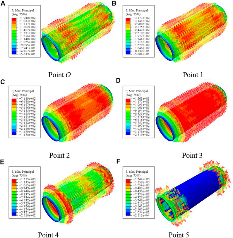
FIGURE 22. Stress distribution of transverse CFRP. (A–F) Stress distribution of transverse CFRP at different 0–5 points.
Parameter Analysis
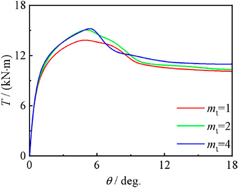
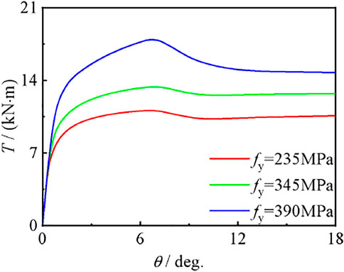
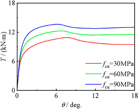
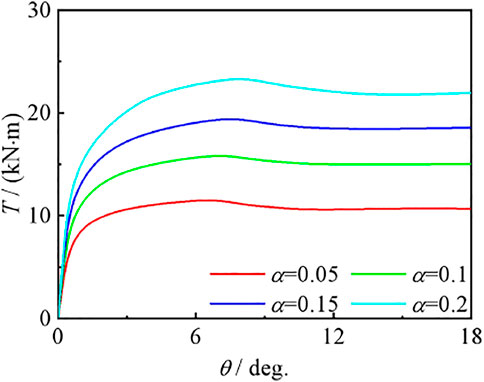
The possible parameters affecting the Tθ curve of compression torsion members include the number of transverse CFRP layers, material strength, steel ratio, and axial compression ratio. Therefore, this is a typical example to analyze the influence of the above parameters on the T–θ curve of CFRP concrete-filled steel tubular compression torsion members.
Influence of Transverse CFRP
Figure 23 shows the effect of the number of transverse CFRP layers on the torque angle (T–θ) curve of compression torsion members. It can be seen that with the increase of mt, the bearing capacity of members increases gradually, and the stiffness in the curve elastic stage has no obvious change. The main reason for this phenomenon is that the carbon fiber cloth has the restraint ability on the specimen, so the change in the number of layers will affect the bearing capacity.
Effect of Material Strength
Figures 24, 25 show the effects of steel yield strength and concrete strength on the torque angle (T–θ) curve of compression torsion members, respectively. It can be seen that with the improvement of material strength, the bearing capacity of members increases, and the curve shape and initial stiffness do not change significantly, but the bearing capacity is improved, and the role of steel is more obvious. Because steel tubes and concrete are the main components of CF-CFRP-ST, the change in their strength plays a decisive role in the bearing capacity of specimens. Macroscopically, the bearing capacity of members is proportional to fy and fcu.
Effect of Steel Ratio
Figure 26 shows the effect of steel content on the torque angle (T–θ) curve of compression torsion members. It can be seen that with the improvement of α, the bearing capacity of the member is significantly improved, and the stiffness in the curve elastic stage is also significantly increased.
Influence of Axial Compression Ratio
Figure 27 shows the effect of the axial compression ratio on the torque angle (T–θ) curve of compression torsion members. It can be seen that the axial compression ratio has a significant impact on the shape and bearing capacity of the curve, but has no significant impact on the stiffness of the initial stage of the curve. The reason is that the torque moment increases with the increase of n so that the load borne by the specimen increases significantly, the energy loss of the member increases, and the macroscopic performance is that the bearing capacity decreases.
Calculation Equation of Bearing Capacity of CF-CFRP-ST Under Compression–Torsion Load
Strength Definition
According to the whole process analysis results of the CF-CFRP-ST compression torsion specimen, through a large number of calculations and the analysis of T–γ relationship curve, it is defined that when the shear strain reaches Eq. 4, the specimen reaches its torsional bearing capacity:
Calculation Equation of Bearing Capacity
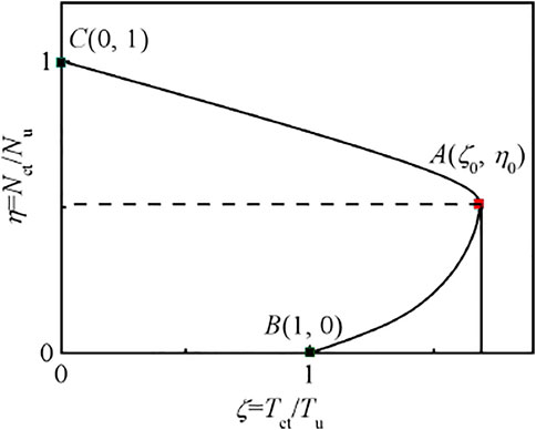
Figure 28 shows the typical Nct/Nu-Tct/Tu relationship curve of CF-CFRP-ST compression torsion members. A large number of parameters are calculated for the T–θ curve, and the calculation parameters (scope of application) are as follows: fy = 235–390MPa, fcu = 30–90MPa, α = 0.05–0.2, ξs = 0.238–0.951, and ξcf = 0.162–0.649.
The results of parameter calculation show that ζ0 and η0 of equilibrium point A can be approximately expressed as a function of the total constraint coefficient ξ. Through the regression analysis of the calculation results, the expressions of ζ0 and η0 can be deduced as follows:
The typical Nct/Nu-Tct/Tu curve of components can be roughly divided into two parts, and the expressions are as follows:
Part A-C (Nct/Nu>η0)
Part B-A (Nct/Nu≤η0)
where a = (1-η0)/ζ0, and b=(1-ζ0)/η02, and c = 2(ζ0-1)/η0。.
Correlation Equation Verification
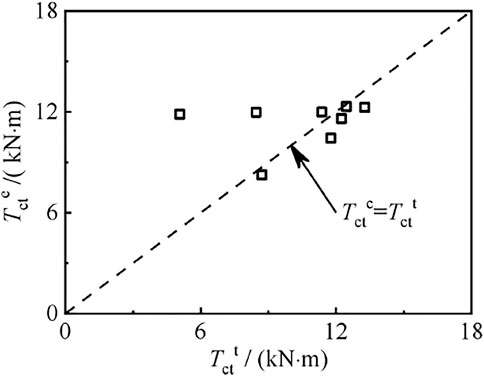
Figure 29 shows the comparison between calculated torsional bearing capacity Tctc and test value Tctt of specimens. The average value of Tctc/Tctt of the member is 0.94 and the mean square deviation is 0.18. It can be seen that the calculated results are in good agreement with the test results.
Conclusion
(1) The T–θ curves of the CF-CFRP-ST specimen can be divided into the elastic stage, the elastic–plastic stage, and the plastic strengthening stage. After reaching the bearing capacity, the specimen can still maintain a considerable bearing capacity after experiencing a large corner, which belongs to ductile failure. The deformation of the specimen basically conforms to the assumption of the plane section.
(2) The T–θ curves and deformation mode of the CF-CFRP-ST specimen can be well simulated by ABAQUS. The stress distribution of each component material of the CF-CFRP-ST specimen under compressive torsional load is analyzed, and the simulation results are in good agreement with the experimental results.
(3) The results of parameter analysis show that the increase of transverse CFRP layers, material strength, and steel ratio can improve the bearing capacity of members. With the increase of axial compression ratio, the bearing capacity of members first increases and then decreases slightly.
(4) The bearing capacity equation of the CF-CFRP-ST specimen under compressive torsional load is proposed. The calculation results of this equation are in good agreement with the experimental results.
Data Availability Statement
The original contributions presented in the study are included in the article/Supplementary Material; further inquiries can be directed to the corresponding author.
Author Contributions
QW conducted experimental research, JZ conducted finite element simulation, and KP translated and contributed the article.
Conflict of Interest
The authors declare that the research was conducted in the absence of any commercial or financial relationships that could be construed as a potential conflict of interest.
Publisher’s Note
All claims expressed in this article are solely those of the authors and do not necessarily represent those of their affiliated organizations, or those of the publisher, the editors, and the reviewers. Any product that may be evaluated in this article, or claim that may be made by its manufacturer, is not guaranteed or endorsed by the publisher.
Acknowledgments
The research reported in the study is supported by the Project for Talent of Liaoning Province of China (No. XLYC1902009), and the authors thank Shenyang jianzhu University for its support in experimental equipment.
References
Chen, Y., Wang, K., He, K., Wei, J., and Wan, J. (2018). Compressive Behavior of CFRP-Confined Post Heated Square CFST Stub Columns. Thin-Walled Struct. 127, 434–445. doi:10.1016/j.tws.2018.02.012
Han, L. H., and Zhong, S. T. (2004). Bearing Capacity Correlation Equations of Concrete Filled Steel Tubular Members under Compression Torsion and Bending Torsion. J. of Harbin Inst. of Archit. Eng. 27 (2), 32–37. (in Chinese). doi:10.15951/j.tmgcxb.2016.10.004
Hou, C. C., Han, L. H., Wang, Q. L., and Hou, C. (2016). Flexural Behavior of Circular Concrete Filled Steel Tubes (CFST) under Sustained Load and Chloride Corrosion. Thin-Walled Struct. 107 (1), 182–196. doi:10.1016/j.tws.2016.02.020
Hu, C. M., and Han, L. H. (2016). Experimental Study on Impact Resistance of Circular Concrete Filled Steel Tubular Composite Members. J. of Civ. Eng. 49 (10), 11–17.
Hua, Y. X., Hou, C., and Han, L. H. (2015). Study on Mechanical Properties of Concrete Filled Steel Tubular Flexural and Torsional Members under Chloride Ion Corrosion Environment. Eng. Mech. 32 (S1), 149–152.
Li, N., Lu, Y. Y., Li, S., and Liu, L. (2018). Slenderness Effects on Concrete-Filled Steel Tube Columns Confined with CFRP. J. of Constr. Steel Res. 143, 110–118. doi:10.1016/j.jcsr.2017.12.014
Liang, J., Lin, S., Li, W., and Liu, D. (2021). Axial Compressive Behavior of Recycled Aggregate Concrete-Filled Square Steel Tube Stub Columns Strengthened by CFRP. Structures 29, 1874–1881. doi:10.1016/j.istruc.2020.12.084
Nie, J.-g., Wang, Y.-h., and Fan, J-S. (2013). Experimental Research on Concrete Filled Steel Tube Columns under Combined Compression-Bending-Torsion Cyclic Load. Thin-Walled Struct. 67, 1–14.doi:10.1016/j.tws.2013.01.013
Nie, J. G. (2005). Stiffness and Capacity of Steel-Concrete Composite Beams with Profiled Sheeting. Eng. Struct. 27 (7), 1074–1085. doi:10.1016/j.engstruct.2005.02.016
Nie, J. G., Wang, Y. H., and Fan, J. S. (2014a). Study on Seismic Behavior of Concrete Filled Steel Tube under Pure Torsion and Compression Torsion Load. Ocean. Eng. 47 (1), 47–58. doi:10.15951/j.tmgcxb.2014.01.008
Nie, J. G., Wang, Y. H., and Fan, J. S. (2014). Study on Seismic Behavior of Concrete Filled Steel Tubular Columns under Pure Torsion and Compression Torsion Load. Steel Compos. Struct. 47 (1), 47–58.
Park, J. W. (2010). Behavior of Concrete Filled Circular Steel Tubes Confined by Carbon Fiber Sheets under Compression and Cyclic Loads. Steel Compos. Struct. 10 (2), 187–205. doi:10.12989/scs.2010.10.2.187
Romero, M. L., Espinos, A., Lapuebla-Ferri, A., Albero, V., and Hospitaler, A. (2020). Recent Developments and Fire Design Provisions for CFST Columns and Slim-Floor Beams. J. of Constr. Steel Res. 172, 106159. doi:10.1016/j.jcsr.2020.106159
Sundarraja, M. C., and Ganesh Prabhu, G. (2011). Finite Element Modeling of CFRP Jacketed CFST Members under Flexural Loading. Thin-Walled Struct. 49 (12), 1483–1491. doi:10.1016/j.tws.2011.07.008
Sundarraja, M. C., and Ganesh, P. G. (2011). Investigation on Strengthening of CFST Members under Compression Using CFRP Composites. J. of Reinf. Plastics Compos. 30 (15), 1251–1264. doi:10.1177/0731684411418018
Tang, H. Y., Chen, J. L., Fan, L. Y., Sun, X. J., and Peng, C. M. (2020). Experimental Investigation of FRP-Confined Concrete-Filled Stainless Steel Tube Stub Columns under Axial Compression. Thin-Walled Struct. 146, 1–14. doi:10.1016/j.tws.2019.106483
Tao, Z., Han, L. H., and Zhuang, J. P. (2008). Cyclic Performance of Fire-Damaged Concrete-Filled Steel Tubular Beam-Columns Repaired with CFRP Wraps. J. of Constr. Steel Res. 64 (1), 37–50. doi:10.1016/j.jcsr.2007.02.004
Tao, Z., Han, L. H., and Wang, L. L. (2007). Compressive and Flexural Behaviour of CFRP Repaired Concrete-Filled Steel Tubes after Exposure to Fire. J. of Constr. Steel Res. 63 (8), 1116–1126. doi:10.1016/j.jcsr.2006.09.007
Tao, Z., Han, L. H., and Zhuang, J. P. (2007). Axial Loading Behavior of CFRP Strengthened Concrete-Filled Steel Tubular Stub Columns. Adv. Struct. Eng. 10 (1), 37–46. doi:10.1260/136943307780150814
Wang, Q. L., Li, J., Shao, Y. B., and Zhao, W. J. (2015). Flexural Performances of Concrete Filled CFRP-Steel Tubes. Adv. Struct. Eng. 18 (8), 1319–1344. doi:10.1260/1369-4332.18.8.1319
Wang, Q. L., and Shao, Y. B. (2014). Compressive Performances of Concrete Filled Square CFRP-Steel Tubes (S-CFRP-CFST). Steel Compos. Struct. 16 (5), 455–480. doi:10.12989/scs.2014.16.5.455
Wang, Q. L., Zhao, Z., Shao, Y. B., and Li, Q. L. (2017). Static Behavior of Axially Compressed Square Concrete Filled CFRP-Steel Tubular (S-CF-CFRP-ST) Columns with Moderate Slenderness. Thin-Walled Struct. 110 (1), 106–122. doi:10.1016/j.tws.2016.10.019
Ye, Y., Han, L. H., and Tao, Z. (2016). Analysis of Influence of Void on Shear Behavior of Concrete Filled Circular Steel Tubular. Eng. Mech. 33 (S1), 62–66.
Zhang, K., Liao, F. Y., and Huang, Z. W. (2019). Study on Axial Compression Behavior of Concrete Filled Steel Tubular Short Columns with Spherical Crown Void Strengthened with CFRP. J. of Build. Struct. 40 (1), 220–225.
Zhang, Y. R., Wei, Y., Zhao, K., Ding, M. M., and Wang, L. B. (2020). Analytical Model of Concrete-Filled FRP-Steel Composite Tube Columns under Cyclic Axial Compression. Soil Dyn. Earthq. Eng. 139, 1–11. doi:10.1016/j.soildyn.2020.106414
Keywords: circular concrete-filled CFRP steel tube, experimental study, finite element study, bearing capacity equation, parameter analysis
Citation: Wang Q-l, Zhao J and Peng K (2022) Static Behavior of Circular Section CFRP Concrete-Filled Steel Tubes Under Compressive–Torsional Load. Front. Mater. 9:869786. doi: 10.3389/fmats.2022.869786
Received: 05 February 2022; Accepted: 16 May 2022;
Published: 15 July 2022.
Edited by:
Jiaqing Wang, Nanjing Forestry University, ChinaReviewed by:
Ali Raza, University of Engineering and Technology Taxila, PakistanQing-feng Liu, Shanghai Jiao Tong University, China
Ping Duan, China University of Geosciences Wuhan, China
Francesco Ascione, University of Salerno, Italy
Copyright © 2022 Wang, Zhao and Peng. This is an open-access article distributed under the terms of the Creative Commons Attribution License (CC BY). The use, distribution or reproduction in other forums is permitted, provided the original author(s) and the copyright owner(s) are credited and that the original publication in this journal is cited, in accordance with accepted academic practice. No use, distribution or reproduction is permitted which does not comply with these terms.
*Correspondence: Kuan Peng, MTE1MTcxMDE3OUBxcS5jb20=
 Qing-li Wang1
 Kuan Peng