 Guifang Duan
 Han Liu
 Zhenyu Liu
95% of researchers rate our articles as excellent or good
Learn more about the work of our research integrity team to safeguard the quality of each article we publish.
Find out more
ORIGINAL RESEARCH article
Front. Mater. , 14 April 2022
Sec. Smart Materials
Volume 9 - 2022 | https://doi.org/10.3389/fmats.2022.850722
This article is part of the Research Topic 2022 Retrospective: Smart Materials View all 4 articles
Reversible deformations of the 4D-printed structures are attractive and promising for various application fields. In this study, the principle of reversible deformations for the bilayer structure consisting of SMP and elastic material is illustrated. By exploring the influence of printing parameters on deformation and resistance, a low-cost reversible bilayer structure with rational resistance distribution is designed to realize reversible deformation. Subsequently, the bilayer structure is employed to design a soft crawling robot with asymmetrical variable friction coefficient feet. By revealing the principle of locomotion by force analysis and deformation process analysis, a wave-like strategy is proposed to actuate the robot. Experiments verify the effectiveness of the designed structures.
4D printing is a smart manufacturing technology integrating 3D printing technology and stimulus responsive material. By 4D printing, the fabricated structure could change their configurations under certain stimuli such as heat, light, water, and electricity (Momeni et al., 2017). The self-deformation ability gives 4D-printed structures a lot of potential applications in various fields, such as drug delivery systems (Fernandes and Gracias, 2012; Guan et al., 2007; Stoychev et al., 2011), cells in spacecraft (Guo et al., 2009), microdevices (An et al., 2011; Mao et al., 2013; Felton et al., 2014; Sun et al., 2015; Miyashita et al., 2015; Wang et al., 2018; Shin and So, 2020), and smart actuators (Kowalewski et al., 2013; Ninh and Bettinger, 2013; Wu et al., 2018; Chen and Peng, 2021; Tang et al., 2021). Therefore, the design of 4D-printed structures is essential to realize expectant deformations. Due to the limitation of the material property, most existent 4D-printed structures are only able to implement one-way deformation and could not return to the initial shape when the external stimulus is canceled. However, in many fields, 4D-printed structures are required to realize reversible deformations for various functions. It is still a challenge to realize controllable reversible deformations.
To date, aiming at the realization of reversible deformations for 4D-printed structures, researchers have proposed a number of methods. According to realization principles of reversible deformations, those methods could be divided into following two categories: material-based methods and composite structure-based methods.
With respect to reversible deformations of 4D-printed structures based on materials, researchers focused on the synthesis of materials that could realize reversible deformations. Based on the synthesis and printing method of liquid crystalline elastomer (LCE), some researchers fabricated 4D-printed structures with the ability to realize reversible deformations (Ambulo et al., 2017; Yuan et al., 2017; López-Valdeolivas et al., 2018; Ceamanos et al., 2020; He et al., 2020; Lu et al., 2020). Some 4D-printed structures fabricated by hydrogels could deform reversibly under stimulations of humidity and temperature (Naficy et al., 2017; Baker et al., 2019; Mao et al., 2016). By adding ferromagnetic particles to the elastomer matrix, Kim et al. (2018) fabricated 4D-printed structures that could deform reversibly are controlled by the magnetic field. Based on the materials with reversibility, it is more flexible to design various reversible deformations. However, compared with commercially available shape memory polymer (PLA), these lab-synthesized materials are costly considering the complicated preparation processes.In addition, requirements for specific environments limit their applications, such as aqueous environments for hydrogels.
With respect to reversible deformations of 4D-printed structures based on composite structures, researchers focused on multilayer structures with different materials (Hu et al., 2019). Mao et al. (2016) designed a composite structure with hydrogel and shape memory polymer (SMP), which realizes reversible deformations by the reversibility of hydrogel with water and modulus change of SMP with temperature change. However, the use of hydrogel makes the structure expensive and inconvenient to be stimulated. Yang et al. (2017) designed a bilayer structure with SMP and carbon fiber, and the reversible bending deformation of the bilayer structure is implemented by changing the power supply to the carbon fiber. Zhao et al. (2019) designed a bilayer structure with SMP and silver ink. Based on reversible deformations of the bilayer structure, a turtle-shaped robot is designed to crawl forward. Wang and Li. (2021b) designed a bilayer structure with SMP and elastomer. Upon heating the structure to a certain high temperature and cooling down to the room temperature, the structure could bend reversibly. However, reversible deformations of these bilayer structures are not large. Wang and Li. (2021a) designed a bilayer structure with conductive SMP and paper, and the bilayer structure could bend reversibly by changing the power supply. Compared with other aforementioned composite structures, this bilayer structure has advantages of low cost, large deformation, and convenient stimulus. However, there is lack of consideration about how the printing parameters affect the resistance of the printed structure. Resistance distribution would affect the heating efficiency of the composite structure. With a poor resistance distribution, different parts of the structure will have different temperatures, and the predicted deformation may not occur.
Considering the aforementioned problems, this study is carried out to design a low-cost bilayer structure with reversible deformation as well as rational resistance distribution based on conductive PLA (an SMP material) and paper. By analyzing the material property of PLA and the printing process of fused deposition modeling (FDM) technology, the principle of reversible deformation for the bilayer structure is declared. To guarantee that the bilayer structure is heated evenly by the Joule effect, the relationships between printing parameters (printing angle and layer thickness) and resistance are developed. In addition, the relationship between the thickness of PLA and the bending angle of the bilayer structure is explored to control the magnitude of the reversible deformation. Based on these relationships, an S-shaped bilayer structure is designed with rational resistance distribution. The reversible deformations can be realized by applying a moderate voltage, which has no requirement for specific environments. Subsequently, the bilayer structure is employed to design a soft crawling robot. The force and deformation analysis of the robot are accomplished to illustrate the principle of locomotion. Based on the proposed principle, a soft crawling robot with variable friction coefficient feet is designed, and a wave-like actuation strategy is proposed.
In this study, in order to realize the electrical control of reversible actuators, the reversible structure is a bilayer structure consisting of conductive PLA (Linan Beisen Company, Zhejiang, China) and paper. The material property of conductive PLA refers to the supplementary data of Wang’s work (Wang and Li. 2021a). The graphene embedded in PLA makes the PLA conductive, and the shape memory effect of PLA retains simultaneously. All structures are printed using a dual-nozzle FDM printer (Raise 3D Pro2 Plus, China).
During the printing process of FDM technology, the printing head moves along the printing path, and the filament is squeezed out to adhere to the construction platform or former layer simultaneously. Therefore, the small piece of the filament between the printing head and former layer is stretched. Along with the temperature decrease, the printed filament remains unchanged due to the constraint of contiguous cooler filaments and construction platform. The process is similar to a manual programming process of SMP, which produces the residual strain in the printed structure along the direction of the printing path. The bilayer structure consisting of conductive PLA and paper is printed, as shown in Figure 1A. It is flat at room temperature. When the bilayer structure is heated, it will bend due to the bigger coefficient of thermal expansion of PLA than that of paper. As the temperature rises, the degree of bending will increase due to larger mismatch of strain between PLA layer and paper. According to the material property of PLA, the elastic modulus of PLA decreases rapidly when the temperature increases above about 50°C. Therefore, the degree of bending will decrease subsequently along with the increase in temperature. When the temperature increases above the glass transition temperature (
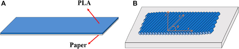
FIGURE 1. (A) Sketch of a bilayer structure. (B) Sketch of rectangular plates.
In FDM technology, the filament is the basic element of the whole printed structure. It is well-known that the resistance of a filament is influenced by its cross-sectional area, resistivity of material, and length. Therefore, the total resistance of a structure is relevant with the layer thickness and printing path. To explore the relationship between them, the thin rectangular plates shown in Figure 1B are printed with different printing parameters. The length, width, and thickness of plates are 50, 10, and 0.6 mm, respectively. In the first group of the plates, to analyze the influence of the printing angle, the layer thickness is set to 0.2 mm, and the printing angle has four different values (0°, 30°, 60°, and 90°). In the second group of the plates, to analyze the influence of the layer thickness, the printing angle is set to 0°, and the layer thickness has four different values (0.05, 0.1, 0.15, and 0.2 mm). In total, five samples are fabricated for each set of parameters. The resistance of every plate in the length direction is measured using the multimeter, and the resistance of the plate with specific parameters is the average of five samples. The results are shown in Tables 1, 2.
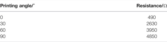
TABLE 1. Resistance of different printing angles.
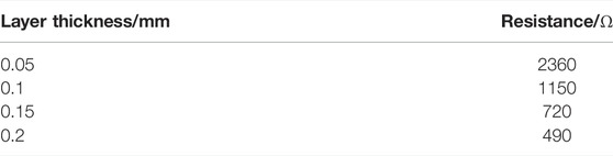
TABLE 2. Resistance of different layer thicknesses.
According to Table 1, it can be seen that the resistance increases dramatically along with the increase in the printing angle. According to the printing principle of FDM technology, there is a gap between adjacent filaments. If the printing angle is not 0°, the electricity will pass through the contact surface and tiny gap of adjacent filaments, which results in the increase of resistance. According to Table 2, the resistance is almost inversely proportional to the layer thickness. Hence, in the design of the bilayer structure, it is critical to take resistance distribution into consideration. Otherwise, the different regions in the structure will have different temperatures if electricity is applied, and the deformation of the structure will fail.
In consideration of the resistance distribution, it is advisable to keep the width of PLA unchanged, and the printing path should be parallel to the route between the locations of two electrodes. To realize better deformation and function, setting two electrodes in the same side of a rectangular area is beneficial. The S-shaped structure is designed as shown in Figure 2. The geometric parameters contain the width of PLA (
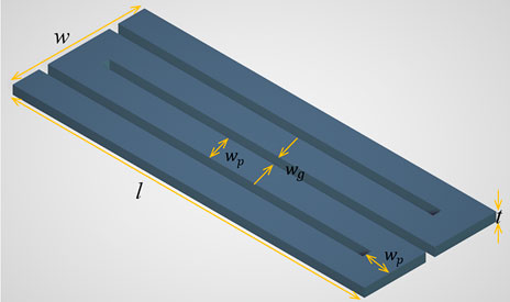
FIGURE 2. Sketch of the S-shaped structure.
According to the law of resistance, the resistance is directly proportional to the length and inversely proportional to the area of the cross section. The resistance of the S-shaped structure can be calculated by the product of the resistance of one PLA strip and the number of PLA strips. Each PLA strip has geometric parameters with length
where
Before identifying the value of

FIGURE 3. Bending angles for different layer thicknesses.
In the following design,
As shown in Figure 2,
where n is the number of PLA strips. Due to the 0.4-mm nozzle, the
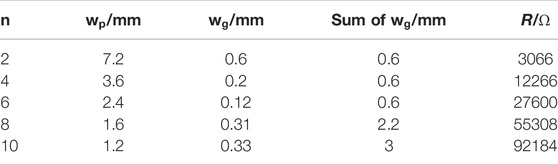
TABLE 3. Design parameters and resistance for different n.
As the sum of
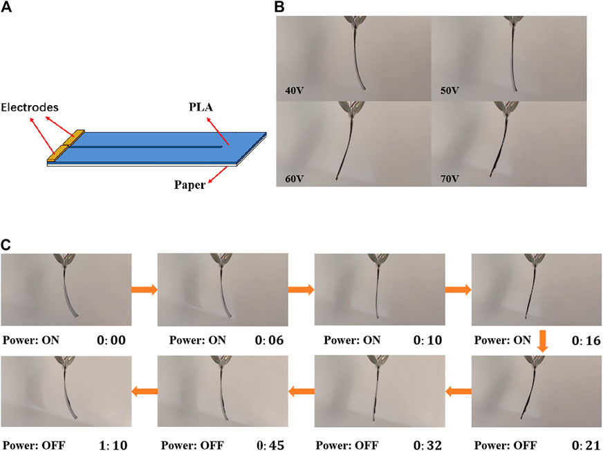
FIGURE 4. (A) Sketch of the reversible bilayer structure. (B) Maximal deformation under different voltages. (C) Deformation process under 70 V.
The designed bilayer structure is printed, and its deformation is observed. To exclude the influence of gravity on deformation, the bilayer structure is clamped vertically. The magnitude of voltage affects the input power, which decides the rate of the temperature change and the maximal temperature. Based on the theoretical analysis, the magnitude of temperature change determines the magnitude of deformation. Hence, under higher voltage, the magnitude of deformation of the bilayer structure will be larger. The configurations at different time under a voltage of 70 V are shown in Figure 4B (Supplementary Video S1). The curved bilayer structure expands gradually, and it finally reaches a small contrary bending compared with that of the initial configuration. Then, when the voltage is removed, the structure returns to the initial configuration. Figure 4C shows the maximal deformation of the bilayer structure under different voltage. It can be found that the magnitude of the deformation is larger for higher voltage. The results are consistent with the proposed principle of reversible deformation.
In this section, a soft crawling robot is designed based on the proposed reversible bilayer structure. Detailed force and deformation analyses are completed to explore the soft crawling robot’s principle of locomotion.
As we know, inchworm can crawl forward by the bending and expanding of its body with variable friction coefficients of feet (Chen et al., 2020). The crawling can be divided into two steps. At first, the body bends, and the rear foot moves forward, while the front foot remains stationary. Then, the body expands, and the front foot moves forward, while the rear foot remains stationary. During the process, the key is the variation of friction coefficients of feet. The sketch of an inchworm-inspired soft crawling robot is shown in Figure 5A. Two reversible bilayer structures are printed in line. The robot realizes crawling by the reversible deformations of the two reversible bilayer structures.
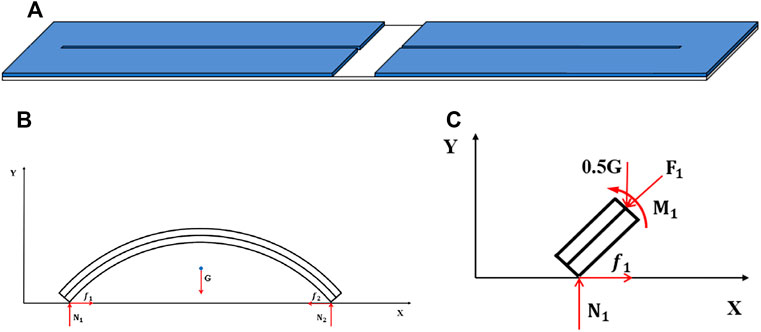
FIGURE 5. (A) Sketch of an inchworm-inspired soft crawling robot. Force analysis of (B) the whole crawling robot and (C) an infinitesimal segment at the left end.
In previous research studies, several different structures have been developed. The simplest strategy is to assign materials with different friction coefficients to the rear and front foot of the crawler (Yang et al., 2016; Yuan et al., 2017). Some researchers designed variable friction coefficient feet by assigning two materials with different friction coefficients to one foot, and different materials contact the ground at different stages during the deformation of a soft robot (Yang et al., 2019; Tang et al., 2019; Yao et al., 2020; Umedachi et al., 2013; Umedachi et al., 2016; Koh and Cho. 2012). In addition, some researchers realize variable friction coefficient feet by magnetic control (Joyee and Pan, 2019; Hua et al., 2020). However, the principle of locomotion in these research studies is abstract, and there are no sufficient force and deformation analysis.
Hence, in the following, the detailed force and deformation analyses are accomplished to reveal the principle of locomotion.
Figure 5B is the force analysis diagram of the crawling robot during the expanding stage. According to our previous work (Liu et al., 2020), when temperature changes, the bilayer structure deforms due to the different elongation ratios of different layers in the axial direction. However, due to the existence of the ground, the deformation is restricted. Hence, the expanding deformation and bending deformation are induced by the union of the internal forces and the external forces.
To reveal the deformation process, as shown in Figure 5C, a detailed force analysis for an infinitesimal segment at the left end of the robot is implemented.
To simplify the deformation analysis, it is assumed that the shape of the bilayer structure remains as an arc during the deformation, which means that the influence of the external forces on shape is ignored. Let
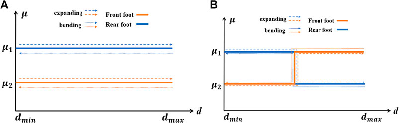
FIGURE 6. Relationship between friction coefficients and distance of (A) the robot with two single friction coefficient feet and (B) the robot with antisymmetric variable friction coefficient feet.
Obviously, for any d, the friction coefficient of each foot at different deformation stages remains unchanged. If the temperature changes slowly, the driving force will increase slowly, and only the foot with a low friction coefficient will move based on the force analysis mentioned previously. After a cycle, the crawling robot will not move forward. In addition, it is worth noting that the conclusion is suitable for any type of feet design, if the two reversible bilayer structures are actuated simultaneously.
Based on the previously mentioned analysis, a crawling robot with variable friction coefficient feet is developed, as shown in Figure 7A. TPU and PLA have different friction coefficients. Two feet are both variable friction coefficient feet, but the changes of friction coefficients for two feet are not symmetric. This means that different angles are required for the rear foot and front foot to change their friction coefficients. In addition, a wave-like actuation strategy is utilized to actuate the robot. The deformation cycle is divided into four stages: 1) front bilayer structure is actuated and expands; 2) rear bilayer structure is actuated and expands; 3) front bilayer structure is unactuated and bends; and 4) rear bilayer structure is unactuated and bends. The friction coefficients of two feet during the expanding and bending deformation are shown in Figure 7B.
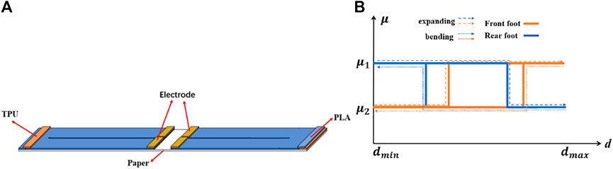
FIGURE 7. (A) Sketch of the developed crawling robot and (B) relationship between friction coefficients and distance.
According to Figure 7B, there are two areas with different ratios of friction coefficients for bending and expanding deformation. This is caused by different transformation angles for the rear foot and front foot. The difference between the changes of
As shown in Figure 8A, arc AC and arc BC represent the rear part and front part, which are tangent at point C. The corresponding bending angles for the rear part and front part are represented by
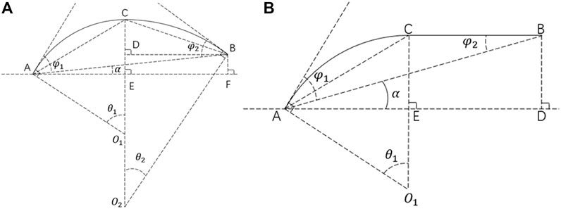
FIGURE 8. Geometric sketch of the robot during (A) first stage and (B) second stage.
According to the trigonometric function, segment AE, EF, and AF are calculated by:
According to the trigonometric function and geometric relationship, segment CE and CD are calculated by
Based on Equations 6 and 7, segment BF is calculated by:
Based on Equations 5 and 8, segment AB and
According to the geometric relationship,
In the second stage, segment BC is horizontal, as shown in Figure 8B.
According to the trigonometric function, segment AE, DE, and AD are calculated by:
According to the trigonometric function and geometric relationship, segment BD and AB are given by:
Based on Equations 15 and 16,
According to geometric relationship,
According to the aforementioned mathematical derivation, the contact angle and distance between two feet are both functions of
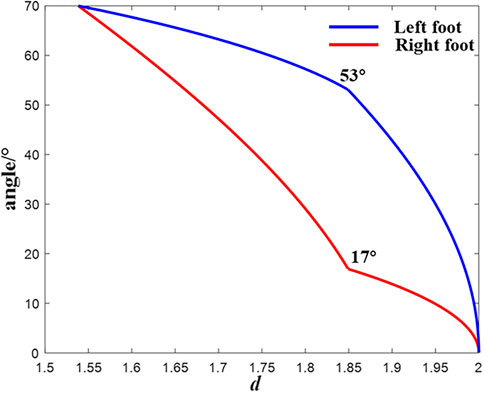
FIGURE 9. Relationship between the contact angle and two feet’s distance.
According to Figure 9, due to the different slopes, the corresponding distance between 17° and 53° is different for the left foot and right foot. According to Figure 7B, there are two areas with different ratios of friction coefficients for bending and expanding deformation. This is caused by the different transformation angles for the rear foot and front foot. Hence, if
The designed soft crawling robot is fabricated, and its deformation is tested. Figure 10 shows the deformations of the robot with different actuation strategies. The first strategy is to apply a voltage of 50 V to two reversible bilayer structures simultaneously. The second is to actuate the robot by a wave-like strategy with a voltage of 50 V.
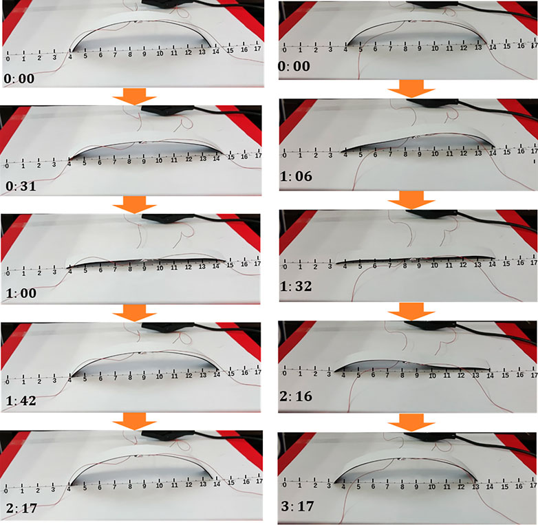
FIGURE 10. Two reversible bilayer structures actuated (A) simultaneously (B) with a wave-like strategy.
According to Figure 10A, the right foot moves at first, and the left foot stays due to a smaller friction coefficient of the right foot. When the temperature rises higher, the friction coefficients of two feet change. The left foot moves, and the right foot stays. Subsequently, the voltage is removed, and the crawling robot undergoes a symmetric deformation. At the end, there is no locomotion after a cycle (Supplementary Video S2).
The deformations of the crawling robot at different stages are shown in Figure 10B (Supplementary Video S3). At each stage, both feet move with different magnitudes. It can be found that there is a 6 mm displacement for each cycle, which illustrates the effectiveness of the designed soft crawling robot and the proposed wave-like actuation strategy.
Several researchers have realized locomotion in their research studies by actuating the two feet simultaneously, which is contradictory to the previous result. We try to give a possible explanation for the locomotion based on the previous force analysis.
If the temperature increases fast enough,
To verify the principle mentioned previously, as shown in Figure 11, a soft crawling robot, which has two feet with different friction coefficients, is fabricated.
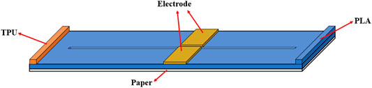
FIGURE 11. Crawling robot with two feet with different friction coefficients.
The deformation of the structure actuated by 50, 60, 70, and 80 V is shown in Figure 12 (Supplementary Videos S4–S7). According to the results, the robot moves 0, 1, 2, and 1 mm, respectively, under 50, 60, 70, and 80 V. It shows that the moving distance increases at first and decreases subsequently as the voltage increases. The value of voltage could affect the input power, which decides the rate of the temperature change. As the voltage increases, the mismatch of strain between paper and PLA becomes larger due to the high rate of temperature change. However, the modulus of PLA becomes smaller simultaneously. The actuation force is related to the product of modulus of PLA and the mismatch of strain. As is well-known, the modulus of PLA decreases dramatically when the temperature approaches its glass transition temperature. This may be the reason that the moving distance increases at first and decreases subsequently as the voltage increases.
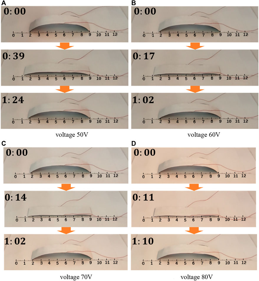
FIGURE 12. Deformation of the structure under different voltage (A) 50 V, (B) 60 V, (C) 70 V, and (D) 80 V.
In addition, in the experiments, if the bilayer structure is under 80 V in a relatively long time, the paper layer of the bilayer structure would burn at the location of the inside edge. Therefore, the designed soft crawling robot obtains a larger crawling step distance in each cycle, and it requires a smaller voltage. Furthermore, the designed robot has no risk of losing efficacy, and it could experience more cycles.
In this study, a low-cost bilayer structure with reversible deformation and rational resistance distribution was designed. By setting the two electrodes in the same side with an S-shaped structure, the designed bilayer structure is available for more applications. The deformation of the printed bilayer structure was consistent with the proposed principle of reversible deformation. A soft crawling robot was developed by combining two bilayer structures, and it could realize locomotion by the proposed wave-like actuation strategy. The principle of locomotion is presented by several analyses. In addition, we found that the magnitude of the applied voltage has significant influence on the locomotion of the soft crawling robot. Experiments show the effectiveness of the proposed principles and structures.
In the future, to expand the application of the proposed principles and designed structures, more materials will be researched to find appropriate elastic material to replace paper. This will improve the potential and flexibility for the design of a 4D-printed soft robot.
The original contributions presented in the study are included in the article/Supplementary Material, further inquiries can be directed to the corresponding author.
GD: conceptualization, methodology, and writing; HL: methodology, data curation, experiment, and writing; ZL: analysis, reviewing, and editing; and JT: supervision and reviewing.
The work was funded by the support from the National Natural Science Foundation of China (Grant No. 51935009 and 52075480), and the High-level Talent Special Support Plan of Zhejiang Province (Grant No. 2020R52004) is gratefully acknowledged.
The authors declare that the research was conducted in the absence of any commercial or financial relationships that could be construed as a potential conflict of interest.
All claims expressed in this article are solely those of the authors and do not necessarily represent those of their affiliated organizations, or those of the publisher, the editors, and the reviewers. Any product that may be evaluated in this article, or claim that may be made by its manufacturer, is not guaranteed or endorsed by the publisher.
The Supplementary Material for this article can be found online at: https://www.frontiersin.org/articles/10.3389/fmats.2022.850722/full#supplementary-material
Ambulo, C. P., Burroughs, J. J., Boothby, J. M., Kim, H., Shankar, M. R., and Ware, T. H. (2017). Four-dimensional Printing of Liquid Crystal Elastomers. ACS Appl. Mater. Inter. 9 (42), 37332–37339. doi:10.1021/acsami.7b11851
An, B., Benbernou, N., Demaine, E. D., and Rus, D. (2011). Planning to Fold Multiple Objects from a Single Self-Folding Sheet. Robotica 29 (1 SPEC. ISSUE), 87–102. doi:10.1017/S0263574710000731
Baker, A. B., Bates, S. R. G., Llewellyn-Jones, T. M., Valori, L. P. B., Dicker, M. P. M., and Trask, R. S. (2019). 4D Printing with Robust Thermoplastic Polyurethane Hydrogel-Elastomer Trilayers. Mater. Des. 163, 107544. doi:10.1016/j.matdes.2018.107544
Ceamanos, L., Kahveci, Z., López-Valdeolivas, M., Liu, D., Broer, D. J., and Sánchez-Somolinos, C. (2020). Four-dimensional Printed Liquid Crystalline Elastomer Actuators with Fast Photoinduced Mechanical Response toward Light-Driven Robotic Functions. ACS Appl. Mater. Inter. 12 (39), 44195–44204. doi:10.1021/acsami.0c13341
Chen, C.-T., and Peng, R.-C. (2021). Design and 3D Printing of Paper-Based Shape Memory Polymer Actuated for Soft Lightweight Fingers. Smart Mater. Struct. 30 (7), 075010. doi:10.1088/1361-665x/ac00ca
Chen, S., Cao, Y., Sarparast, M., Yuan, H., Dong, L., Tan, X., et al. (2020). Soft Crawling Robots: Design, Actuation, and Locomotion. Adv. Mater. Technol. 5 (2), 1900837–1900920. doi:10.1002/admt.201900837
Felton, S., Tolley, M., Demaine, E., Rus, D., and Wood, R. (2014). A Method for Building Self-Folding Machines. Science 345 (6197), 644–646. doi:10.1126/science.1252610
Fernandes, R., and Gracias, D. H. (2012). Self-folding Polymeric Containers for Encapsulation and Delivery of Drugs. Adv. Drug Deliv. Rev. 64 (14), 1579–1589. doi:10.1016/j.addr.2012.02.012
Guan, J., He, H., Lee, L. J., and Hansford, D. J. (2007). Fabrication of Particulate Reservoir-Containing, Capsulelike, and Self-Folding Polymer Microstructures for Drug Delivery. Small 3 (3), 412–418. doi:10.1002/smll.200600240
Guo, X., Li, H., Yeop Ahn, B., Duoss, E. B., Hsia, K. J., Lewis, J. A., et al. (2009). Two- and Three-Dimensional Folding of Thin Film Single-Crystalline Silicon for Photovoltaic Power Applications. Proc. Natl. Acad. Sci. U.S.A. 106 (48), 20149–20154. doi:10.1073/pnas.0907390106
He, Q., Wang, Z., Wang, Y., Song, Z., and Cai, S. (2020). Recyclable and Self-Repairable Fluid-Driven Liquid Crystal Elastomer Actuator. ACS Appl. Mater. Inter. 12 (31), 35464–35474. doi:10.1021/acsami.0c10021
Hu, F., Lyu, L., and He, Y. (2019). A 3D Printed Paper-Based Thermally Driven Soft Robotic Gripper Inspired by Cabbage. Int. J. Precis. Eng. Manuf. 20 (11), 1915–1928. Korean Society for Precision Engineering: 1915–1928. doi:10.1007/s12541-019-00199-6
Hua, D., Liu, X., Sun, S., Sotelo, M. A., Li, Z., and Li, W. (2020). A Magnetorheological Fluid-Filled Soft Crawling Robot with Magnetic Actuation. Ieee/asme Trans. Mechatron. 25 (6), 2700–2710. doi:10.1109/TMECH.2020.2988049
Joyee, E. B., and Pan, Y. (2019). A Fully Three-Dimensional Printed Inchworm-Inspired Soft Robot with Magnetic Actuation. Soft Robotics 6 (3), 333–345. doi:10.1089/soro.2018.0082
Kim, Y., Yuk, H., Zhao, R., Chester, S. A., and Zhao, X. (2018). Printing Ferromagnetic Domains for Untethered Fast-Transforming Soft Materials. Nature 558 (7709), 274–279. doi:10.1038/s41586-018-0185-0
Koh, J.-S., and Cho, K.-J. (2013). Omega-shaped Inchworm-Inspired Crawling Robot with Large-Index-and-Pitch (LIP) SMA Spring Actuators. Ieee/asme Trans. Mechatron. 18 (2), 419–429. doi:10.1109/TMECH.2012.2211033
Kowalewski, J., Mahler, T., Reichardt, L., and Zwick, T. (2013). Shape Memory Alloy (SMA)-Based Pattern-Reconfigurable Antenna. IEEE Antennas Wireless Propagation Lett. 12, 1598–1601. doi:10.1109/lawp.2013.2293593
Liu, Z., Liu, H., Duan, G., and Tan, J. (2020). Folding Deformation Modeling and Simulation of 4D Printed Bilayer Structures Considering the Thickness Ratio. Mathematics Mech. Sol. 25 (2), 348–361. doi:10.1177/1081286519877563
López-Valdeolivas, M., Liu, D., Broer, D. J., and Sánchez-Somolinos, C. (2018). 4D Printed Actuators with Soft-Robotic Functions. Macromol. Rapid Commun. 39 (5), 1700710–1700719. doi:10.1002/marc.201700710
Lu, X., Ambulo, C. P., Wang, S., Rivera‐Tarazona, L. K., Kim, H., Searles, K., et al. (202120783). 4D‐Printing of Photoswitchable Actuators. Angew. Chem. Int. Ed. 60, 5536–5543. doi:10.1002/anie.202012618
Mao, S., Dong, E., Xu, M., Jin, H., Li, F., and Yang, J. (2013). “Design and Development of Starfish-like Robot: Soft Bionic Platform with Multi-Motion Using SMA Actuators,” in 2013 IEEE International Conference on Robotics and Biomimetics, ROBIO, 2013 (December) (IEEE), 91–96. doi:10.1109/ROBIO.2013.6739441
Mao, Y., Ding, Z., Yuan, C., Ai, S., Isakov, M., Wu, J., et al. (2016). 3D Printed Reversible Shape Changing Components with Stimuli Responsive Materials. Sci. Rep. 6, 1–13. doi:10.1038/srep24761
Miyashita, S., Guitron, S., Ludersdorfer, M., Sung, C. R., and Rus, D. (2015). “An Untethered Miniature Origami Robot that Self-Folds, Walks, Swims, and Degrades,” in Proceedings - IEEE International Conference on Robotics and Automation 2015-June (IEEE), 1490–1496. doi:10.1109/ICRA.2015.7139386
Momeni, F., Mehdi Hassani.N, S. M., Liu, X., and Ni, J. (2017). A Review of 4D Printing. Mater. Des. 122, 42–79. doi:10.1016/j.matdes.2017.02.068
Naficy, S., Gately, R., Gorkin, R., Xin, H., and Spinks, G. M. (2017). 4D Printing of Reversible Shape Morphing Hydrogel Structures. Macromol. Mater. Eng. 302 (1), 1600212–1600219. doi:10.1002/mame.201600212
Ninh, C., and Bettinger, C. J. (2013). Reconfigurable Biodegradable Shape-Memory Elastomers via Diels-Alder Coupling. Biomacromolecules 14 (7), 2162–2170. doi:10.1021/bm4002602
Shin, S., and So, H. (2020). Effect of 3D Printing Raster Angle on Reversible Thermo-Responsive Composites Using PLA/paper Bilayer. Smart Mater. Struct. 29 (10), 105016. doi:10.1088/1361-665X/aba490
Stoychev, G., Puretskiy, N., and Ionov, L. (2011). Self-folding All-Polymer Thermoresponsive Microcapsules. Soft Matter 7 (7), 3277–3279. doi:10.1039/c1sm05109a
Sun, X., Felton, S. M., Niiyama, R., Wood, R. J., and Kim, S. (2015). “Self-folding and Self-Actuating Robots: A Pneumatic Approach,” in Proceedings - IEEE International Conference on Robotics and Automation 2015-June (IEEE), 3160–3165. doi:10.1109/ICRA.2015.7139634
Tang, X., Li, K., Liu, Y., Zhou, D., and Zhao, J. (2019). A Soft Crawling Robot Driven by Single Twisted and Coiled Actuator. Sensors Actuators A: Phys. 291, 80–86. doi:10.1016/j.sna.2019.03.049
Tang, Y., Dai, B., Su, B., and Shi, Y. (2021). Recent Advances of 4D Printing Technologies toward Soft Tactile Sensors. Front. Mater. 8, 1–10. doi:10.3389/fmats.2021.658046
Umedachi, T., Vikas, V., and Trimmer, B. A. (2013). “Highly Deformable 3-D Printed Soft Robot Generating Inching and Crawling Locomotions with Variable Friction Legs,” in IEEE International Conference on Intelligent Robots and Systems (IEEE), 4590–4595. doi:10.1109/IROS.2013.6697016
Umedachi, T., Vikas, V., and Trimmer, B. A. (2016). Softworms : the Design and Control of Non-pneumatic, 3D-Printed, Deformable Robots. Bioinspir. Biomim. 11 (2), 025001. doi:10.1088/1748-3190/11/2/025001
Wang, G., Cheng, T., Do, Y., Yang, H., Tao, Y., Gu, J., et al. (2018). “Printed Paper Actuator,” in Conference on Human Factors in Computing Systems - Proceedings, 2018-April, 1–12. doi:10.1145/3173574.3174143
Wang, Y., and Li, X. (2021a). 4D Printing Reversible Actuator with Strain Self-Sensing Function via Structural Design. Composites B: Eng. 211, 108644. doi:10.1016/j.compositesb.2021.108644
Wang, Y., and Li, X. (2021b). 4D-printed Bi-material Composite Laminate for Manufacturing Reversible Shape-Change Structures. Composites Part B: Eng. 219, 108918. doi:10.1016/j.compositesb.2021.108918
Wu, Y., Ho, K. Y., Kariya, K., Xu, R., Cai, W., Zhong, J., et al. (2018). “PRE-curved PVDF/PI Unimorph Structures for Biomimic Soft Crawling Actuators,” in Proceedings of the IEEE International Conference on Micro Electro Mechanical Systems (MEMS), 2018-January (IEEE), 581–584. doi:10.1109/MEMSYS.2018.8346620
Yang, C., Wang, B., Li, D., and Tian, X. (2017). Modelling and Characterisation for the Responsive Performance of CF/PLA and CF/PEEK Smart Materials Fabricated by 4D Printing. Virtual Phys. Prototyping 12 (1), 69–76. doi:10.1080/17452759.2016.1265992
Yang, Y., Tse, Y. A., Zhang, Y., Kan, Z., and Wang, M. Y. (2019). “A Low-Cost Inchworm-Inspired Soft Robot Driven by Supercoiled Polymer Artificial Muscle,” in RoboSoft - 2019 IEEE International Conference on Soft Robotics (IEEE), 161–166. doi:10.1109/ROBOSOFT.2019.8722784
Yang, Z., Zhu, L., Li, B., Sun, S., Chen, Y., Yan, Y., et al. (2016). Mechanical Design and Analysis of a Crawling Locomotion Enabled by a Laminated Beam. Extreme Mech. Lett. 8, 88–95. doi:10.1016/j.eml.2016.03.014
Yao, T., Wang, Y., Zhu, B., Wei, D., Yang, Y., and Han, X. (2020). 4D Printing and Collaborative Design of Highly Flexible Shape Memory alloy Structures: a Case Study for a Metallic Robot Prototype. Smart Mater. Struct. 30 (1), 015018. doi:10.1088/1361-665X/abcc0a
Yuan, C., Roach, D. J., Dunn, C. K., Mu, Q., Kuang, X., Yakacki, C. M., et al. (2017). 3D Printed Reversible Shape Changing Soft Actuators Assisted by Liquid crystal Elastomers. Soft Matter 13 (33), 5558–5568. doi:10.1039/c7sm00759k
Keywords: reversible deformation, soft crawling robot, 4D printing, composite structure, force and deformation analysis
Citation: Duan G, Liu H, Liu Z and Tan J (2022) A 4D-Printed Structure With Reversible Deformation for the Soft Crawling Robot. Front. Mater. 9:850722. doi: 10.3389/fmats.2022.850722
Received: 08 January 2022; Accepted: 14 March 2022;
Published: 14 April 2022.
Edited by:
Stefano Pandini, University of Brescia, ItalyReviewed by:
Tongqing Lu, Xi’an Jiaotong University, ChinaCopyright © 2022 Duan, Liu, Liu and Tan. This is an open-access article distributed under the terms of the Creative Commons Attribution License (CC BY). The use, distribution or reproduction in other forums is permitted, provided the original author(s) and the copyright owner(s) are credited and that the original publication in this journal is cited, in accordance with accepted academic practice. No use, distribution or reproduction is permitted which does not comply with these terms.
*Correspondence: Jianrong Tan, ZWdpQHpqdS5lZHUuY24=
Disclaimer: All claims expressed in this article are solely those of the authors and do not necessarily represent those of their affiliated organizations, or those of the publisher, the editors and the reviewers. Any product that may be evaluated in this article or claim that may be made by its manufacturer is not guaranteed or endorsed by the publisher.
Research integrity at Frontiers
Learn more about the work of our research integrity team to safeguard the quality of each article we publish.