 Luming Zhang
 Hao Xin
 Dan Zhao
 Zhiqiang Li3
94% of researchers rate our articles as excellent or good
Learn more about the work of our research integrity team to safeguard the quality of each article we publish.
Find out more
ORIGINAL RESEARCH article
Front. Mater., 03 March 2022
Sec. Computational Materials Science
Volume 9 - 2022 | https://doi.org/10.3389/fmats.2022.849051
This article is part of the Research TopicModeling and Simulation of the Mechanical Behavior of Multi-principal Element MaterialsView all 8 articles
Molecular dynamics simulation method was used to study the influence of co-lattice twin boundary (TB) spacing on the deformation behavior of Al0.1CoCrFeNi high-entropy alloy single crystal under uniaxial tension. Studies have shown that there is a “critical distance” between the twin boundaries, and the sensitivity of the two sides to the change of the twin spacing is different, and the influence of the evolution of the deformation mechanism of the different twin spacing is analyzed from the number of defects and the evolution of the dislocation density. The results show that as the distance between twins decreases, the deformation mechanism gradually transforms from dislocation slip accompanied by defects, such as stacking faults and secondary twins, to a deformation mode of amorphous phase transition. The research aims to provide guidance and reference for the design of high-performance high-entropy alloys.
High-entropy alloys (HEAs) are new types of alloys discovered in recent years and have attracted widespread attention from researchers because of their unique properties. High-entropy alloy has demonstrated its excellent mechanical and chemical properties, such as high hardness (Chen et al., 2013), high strength (Yeh et al., 2004), high wear resistance (Chuang et al., 2011), high thermal stability, high corrosion resistance, etc., which is considered to be a new high-performance metal material with great application potential. The high mixing entropy combined with the slow diffusion of atoms promotes the formation of simple solid solution phases with multiple principal elements in HEAs. These new components in face-centered cubic (FCC), body-centered cubic (BCC), and hexagonal close-packed (HCP) structures provide an expanded solid solution phase with a single or matrix phase at the atomic level, so HEAs have unique characteristics (Saito et al., 2003; Shun and Du, 2009).
AlCoCrFeNi high-entropy alloy is one of the first high-entropy alloy systems to be studied, and its excellent mechanical properties make it have great development and research prospects. More and more studies explored the reasons for its excellent performance (Wang et al., 2012; Ma et al., 2013; Kumar et al., 2015). A lot of studies have been carried out on the simulation of the evolution of micro-structure of high-entropy alloy structures. Li et al. (2016) studied the mechanical behavior of AlCrFeCuNi high-entropy alloy under uniaxial tensile load using atomic simulation methods, and the effects of dislocations and defects on metal plastic deformation were explained. The main mechanism is dislocation pinning, and its plastic deformation mechanism was analyzed; Sharma and Balasubramanian (2017) used classical molecular simulation methods to study the deformation mechanism of Al0.1CoCrFeNi alloy under tensile load. It is found that in the process of plastic deformation, dislocation nucleation and mobility play a vital role in the generation of twin boundaries; Y. Afkham et al. (2017) simulated the tensile behavior of AlCrCoFeCuNi amorphous alloys and explained the influence of Al content and strain rate effects on high-entropy alloys through free bulk modulus and cut band; Li et al. (2019) used molecular dynamics simulation methods to study AlCoCrFeCuNi high-entropy alloys prepared under different cooling rates and deformation behaviors, which is very meaningful for guiding the control of the cooling rate and then the high-strength high-entropy alloys;
Grain boundaries are one of the inevitable important defects in metal materials. In the experiment, a large number of defects will appear in the heat treatment, recrystallization, and other processes, which makes researchers pay more and more attentions. Among them, the twin boundary is a special kind of grain boundary with low strain energy, and both sides of the twin boundary are symmetrical along the grain boundary Twins are as effective as traditional grain boundaries for the strengthening effect of materials. This provides an effective measure to improve the tensile ductility of the material: introducing twin boundaries as defects in the crystals to increase the strength of the material by hindering the movement of dislocations (Saito et al., 2003; Lu et al., 2009). Tadmor. (2004) calculated the origin of twins by first principles and showed that twins can be the main deformation form of metastable face-centered cubic high-entropy alloys. Tian-Zhan Shen et al. (2021) explored the effect of twin boundaries on the mechanical behavior of Cr26Mn20Fe20Co20Ni14 high-entropy alloys. As the distance between twin boundaries decreases, the major deformation mechanism of Cr26Mn20Fe20Co20Ni14 high-entropy alloys has changed from dislocation slip to the amorphous phase.
However, the influence mechanism of twin boundaries on the mechanical behavior of Al0.1CoCrFeNi high-entropy alloys lacks in-depth and systematic research. In addition, it is difficult to directly observe the microscopic mechanism of twin boundary changes during tensile deformation test. To further explore the deformation behavior and microstructure development of twins in Al0.1CoCrFeNi, this paper uses prefabricated Al0.1CoCrFeNi nano-twin high-entropy alloys (nt-HEAs) as a model material for related research.
In MD simulation, LAMMPS (Thompson et al., 2022) is used to simulate the tensile behavior of the Al0.1CoCrFeNi model with pre-prepared twin boundaries. Atomsk (Hirel, 2015) is a widely used crystal structure modeling software (S. Yan et al., 2020). The samples are constructed through the Atomsk software package, as shown in Figure 1A. The proportions of Al, Co, Cr, Fe, and Ni atoms are 2.4, 24.4, 24.4, 24.4, 24.4%. To create the random HEAs structures, Al atoms were randomly selected and replaced with Co, Cr, Fe, Ni until the desired composition was achieved.
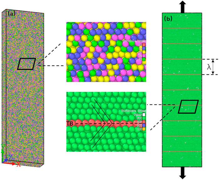
FIGURE 1. Model of the single crystalline FCC Al0.1CoCrFeNi HEAs. (A) Atomic distribution of the nt-HEAs; (B) model structure of the nt-HEAs, in which the green regions represent the FCC structure and the red regions represent the twin boundary (TB).
To explore the influence of different twin boundary densities on the mechanical properties of Al0.1CoCrFeNi, the models of equal twin spacing were prepared in advance, and six models with different twin spacing were set, as shown in Figure 1B. The twin boundary spacing λ is 0.61, 1.84, 3.08, 4.31, 5.55, 6.78 nm in sequence; λ = 0.61 nm is the theoretical minimum distance between twin boundaries composed of three atoms (S. Yan et al., 2020). The model size of 110 Å × 200 Å × 55 Å (X × Y × Z) containing between 518,000 and 528,000 atoms is generated. The X, Y, and Z crystal directions of the model correspond to [-110], [111] and [11-2]. Periodic boundary conditions were used in three directions.
The high-entropy alloy is prepared from five kinds of atoms. Due to the lattice distortion caused by different atomic sizes, energy minimization was carried out using the conjugate gradient relaxation algorithm for the relaxation of the randomized HEAs configuration. The relaxed structure was initialized under an isobaric-isothermal (NPT ensemble) system at room temperature (300 K) with a pressure of 0 MPa for 30,000 steps.
After the relaxation, the uniaxial tensile deformation of the pre-prepared twin boundaries HEAs was applied at room temperature and constant strain rate (1 × 10⁹ s−1) in which the length (in the Y-direction) of the HEAs was gradually increased (Figure 1A). Strain is applied every fixed time step, and then the atomic state and thermodynamic information at equilibrium are calculated. Then, the quasi-static loading of the model is realized.
The correct selection of the EAM potential is the key to ensuring the accuracy and reliability of the molecular dynamics simulation results. This paper uses the EAM potential proposed by Frank et al. (Farkas and Caro, 2020) to simulate the interaction between atoms. This potential function has been successfully applied to the simulation study of the mechanical properties of Al0.1CoCrFeNi and obtained reliable research results (Doan et al., 2020; Fourmont et al., 2020).
The open-source software Ovito (Stukowski, 2010), an open-source visualization software, was used for the data generated by MD simulation. The local atomic structure was analyzed by CNA (common-neighbor analysis) (Faken and Jónsson, 1994), four types of atoms were marked in color: green atoms for fcc structure, blue atoms for bcc structure, red atoms for stacking faults, and white atoms for grain boundaries or dislocation cores. Crystalline defects were analyzed by the DXA (Stukowski et al., 2012) (dislocation analysis) method, and four types of defects will be important in the analyses to come, i.e., Stair-rods, Hirth locks, Shockley, and Perfect dislocations. Perfect dislocations and Shockley dislocations are glossily and enable plasticity; whereas Stair-rods and Hirth locks are sessile and hence regarded as barriers to dislocation motion (Z. Yan and Lin, 2019). Crystal Analysis Method (Stukowski, 2014) is also used to quantitatively analyze the evolution process of martensite transformation, plane defect density including TBs, stacking faults, martensite transformation, etc.
To explore the effect of different twin spacings on the mechanical properties of Al0.1CoCrFeNi high-entropy alloys, the tensile behavior of nt-HEAs is simulated, and the stress-strain curves of the nt-HEAs model with different twin spacings are shown in Figure 2.
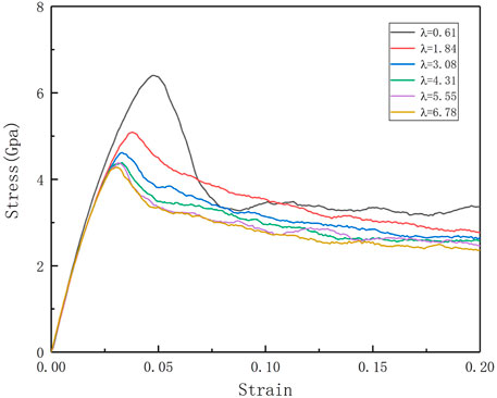
FIGURE 2. Stress-strain curves of nt-HEAs model with different distances between twin boundaries under tension at 300 K.
At a constant loading strain rate (109 s−1), the tensile deformation of the nt-HEAs exhibits typical elastic-yielding-plastic deformation stages. The first stage is the elastic stage: at the initial deformation stage, the stress is a linear increase with the increase of strains, which is similar to the mechanical behavior of the single-crystal metals. The deformation at this stage is manifested as elastic deformation, and the deformation will be restored once the load is stopped; Through the stress-strain curve and linear fitting, we can obtain Young’s modulus E, which is one of the important characteristics of the mechanical properties of materials. Through the comparison of the calculation results, it is found that the distance between the twin boundaries has no significant effect on the elastic model of the HEAs material.
As the load continues, the nt-HEAs material model enters the yield stage. After reaching the maximum stress peak, the stress will drop dramatically. This is due to the higher strain rate. At this time, the stress-strain curve is nonlinear. Continue to load the model, along with the stress-yielding platform, the stress tends to stabilize and fluctuate up and down. This stage belongs to the plastic deformation stage. Li et al. (2016) used the method of atomic simulation to study the mechanical behavior of AlCrFeCuNi high-entropy alloy under uniaxial tensile load, which is more consistent with the trend of the stress-strain curve obtained in this paper.
Figure 3A shows the relationship between yield strength and yield strain as a function of twin boundary distance (λ). The twin boundary distance and the yield strength of the corresponding model are in a Hall–Petch relationship:
where σ0 is the friction stress, k is the constant, and λ is the twin boundary distance. The relationship between yield stress and λ−1/2 shows in Figure 3B.
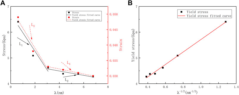
FIGURE 3. (A) Evolutions of the yield stress and yield strain of the nt-HEAs with the twin boundary spacing. (B) The relationship between yield stress and λ−1/2.
The yield strength decreases as the twin boundary distance (λ) increases; In addition, a similar effect also appears in the yield strain. Song and Sun. (2015) found the reverse Hall–Petch relationship in the study of the effect of twin spacing on the mechanical properties of single crystal Cu. In this paper, there is no reverse Hall–Petch relationship, which may be related to the low stacking fault energy caused by high entropy in this paper (Xiao and Deng, 2020).
The yield behavior of nano-twinned metals depends on the competitive relationship between the number of dislocation sources and the repulsive force generated by the twin boundaries for dislocations. Therefore, further analysis was performed on the changes in dislocation density and twin density. And the twin boundary has a certain sensitivity to the strengthening of nt-HEAs materials: when the twin boundary distance λ decreases from 6.98 to 3.08 nm, the yield strength increases from 4.27 to 4.68 GPa, an increase of about 9.6%; when the twin spacing λ decreases from 3.08 to 0.61 nm, the yield strength increases from 4.68 to 6.61 Gpa, an increase of about 41.2%, which shows that when the critical twin boundary distance is reached, the improvement of the yield strength by the twin boundary distance is more significant. The results also show that a similar effect also appears in the yield strain. The yield behavior of nano-twinned metals depends on the competitive relationship between the number of dislocation sources and the repulsive force generated by the twin boundary for dislocations. Therefore, we further analyze the evolution of dislocation density and twin density. Generally, the dislocation density is defined as the ratio of the total length of dislocation lines and the volume of the crystal. However, it is also noted that a distribution of dislocations is theoretically a means to model the crack with the dislocation density indicating the crack displacement, and the dislocations may interact with the applied strains (Dong et al., 2021a; Dong et al., 2021b). In this paper, twin density refers to the ratio of the total length of dislocation lines and the volume of the crystal.
Through the evolution of the twin density and dislocation density in Figure 4, the following conclusions can be found: as the twin density increases, the yield strain produced by the dislocation is gradually lagging, and the twinning distance of 3.08 nm is the “critical distance”; In the model with λ > 3.08 nm, the dislocation density evolution is no longer significantly different, and the yield strain point is very close; when λ < 3.08 nm, the dislocation density has a significant decrease, and the dislocation start point is delayed phenomenon. From the perspective of planar fault density (TB), the higher-density nt-HEAs model started to have a large range of detwinning. Although the low-density nt-HEAs model also experienced detwinning, its density changed not so obvious, and with the generation of secondary twins in the later period, the twin density rises again.
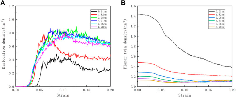
FIGURE 4. (A) Evolution curves of dislocation density ρ during deformation of the nt-HEAs with different twin boundary spacing. (B) Evolution curves of the planar twin (TB) densities as a function of strain.
Through the analysis of these two perspectives, we can further understand the competitive relationship between twins and dislocation sources in the yield behavior of nt-HEAs: when the twin spacing λ is less than 3.08 nm, the repulsive force of the twin boundary on the dislocation in the HEAs model yield behavior occupy the dominant position. At this time, the strengthening trend of the yield strength of the material due to the distance between the twin grain boundaries is shown in the curve L1 in Figure 3. When the twin spacing λ is larger than 3.08 nm, the influence of the twin boundary on the material gradually decreases, the dislocation source is no longer very close to the twin planar, and the dislocation source occupies the main influence position (Guo and Xia, 2011). The change trend of the yield strength is as shown in the curve L2 in Figure 3. For the yield strain, similar to the effect on the yield strength, high-density nt-HEAs will make its yield strain lag behind, and the changing trend of its yield strain is shown in the curves L3 and L4 in Figure 3, which is similar to the research of Shen et al. (2021). The research results indicate that the reduction of the twin boundary spacing not only increases the yield strength of the nt-HEAs model but also makes the yield strain of the HEAs model lag behind.
By observing the plastic deformation part of the stress-strain curve of the HEAs model, it is found that as the strain increases, the stress gradually decreases, and the decline of the twinning spacing narrowing nt-HEAs is more significant. To quantitatively describe the influence of different twin boundary spacings on the plastic deformation behavior of nt-HEAs, the average flow stress of nt-HEAs with different twin boundary spacings between 10 and 15% strain is calculated, and the distribution is shown in Figure 5. The ultra-high-density nt-HEAs (λ = 0.61) has higher average flow stress, which is significantly different from other high-density pre-twinned high-entropy alloy models. It shows that there may be different plastic deformation behaviors with different twin spacing, which will be discussed in the next section.
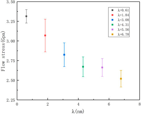
FIGURE 5. Average flow stress distribution of the nt-HEAs with different twin boundary spacing at 10–15% strain range.
The evolution of the microstructure of the material determines the strength and plasticity of the material. In the process of simulation calculation, the strength is reflected in the hindering effect of the microstructure contained in the model on the movement of dislocations, and the plasticity reflects its storage capacity for dislocations. In the calculation process, the calculation model including high-density twins, the prediction of yield strength, yield strain point, average flow stress, and plastic properties are significantly better than other HEAs models with lower density twins. To further clarify the effect of the twinning microstructure on many mechanical properties of the material, and to explore the influence of the distance between the twin boundaries on the mechanical properties of the plastic deformation of the high-entropy alloy, three different twin distances of 0.61, 3.08, and 6.78 nm were constructed and have been analyzed. The selection of different twin spacing is based on the comprehensive consideration of the difference in average flow stress and the stress (strain) sensitive size. Figure 6 reflects the stress-strain curves of the three different spacing models, the evolution of the dislocation density, and the evolution of the planar fault density. With the increase of twin spacing, the following changes can be found:
1. For the stress-strain curve, the yield strength gradually increases and the yield strain gradually lags behind.
2. For the plane stacking fault density, the initial twin density decreases gradually, and the twin density decreases with the increase of strain; There are more regions of intrinsic stacking faults and martensitic transformation.
3. For the perspective of dislocation density, the evolution of dislocation density first increases and then decreases.
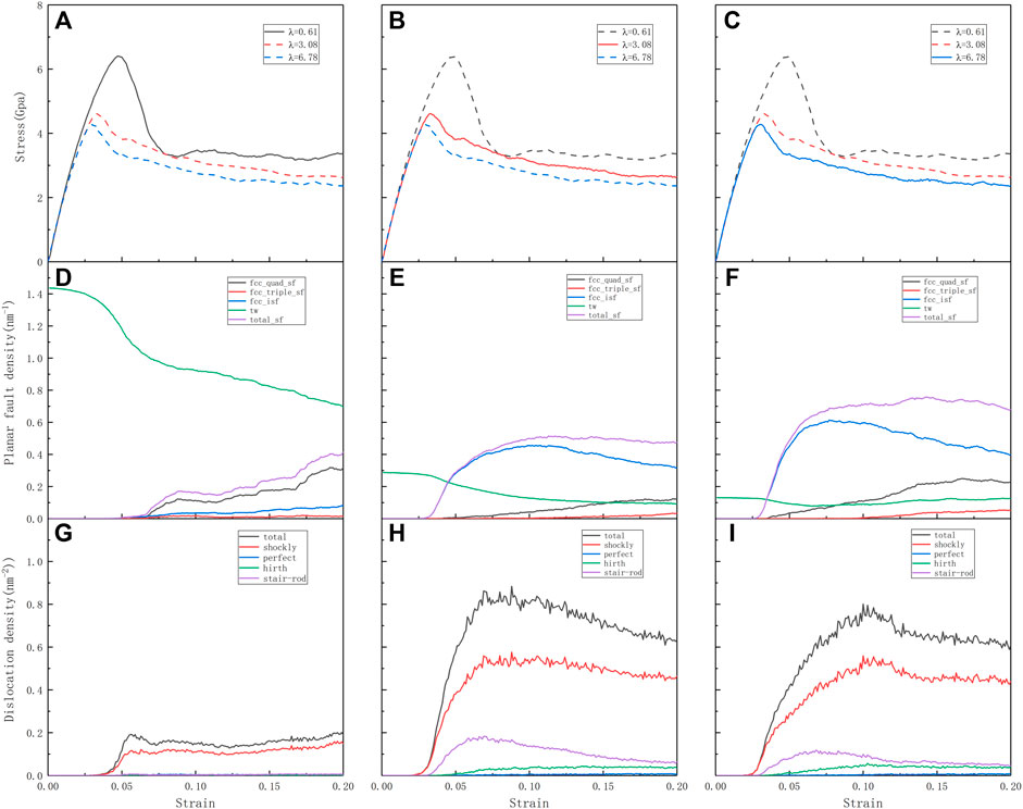
FIGURE 6. (A–C) Tensile stress-strain curves for the different twin spacing nt-HEAs (λ = 0.61, λ = 3.08, λ = 6.78) and deformed along the [111] crystallographic directions, respectively. The corresponding (D–F) planar fault (TB and SF) densities and (G–I) dislocation densities as functions of strain, respectively.
Figure 7 shows the structural snapshot and dislocation evolution diagram of the nt-HEAs model with twin spacing λ = 6.78 nm.
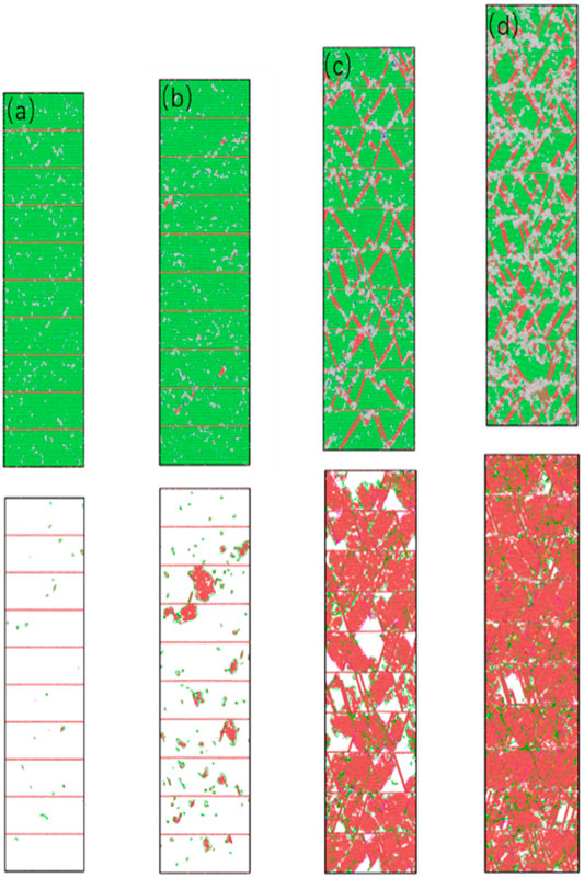
FIGURE 7. The microstructure of nt-HEAs (λ = 6.78 nm) under different strains (A) 2.4%, (B) 2.9%, (C) 10%, and (D) 15%.
During tensile loading, when the strain reaches 0.024, the dislocation source of the model begins to appear, the number of dislocation sources emitted from the twin plane is relatively small, but mainly emitted from between the twins. The orientation of the grains on both sides of the co-lattice twin boundary is mirror-symmetrical for the grain boundary. Since the atoms on the interface are completely located on the lattice positions of the crystals on both sides, the coherent twin boundary is the lowest and most stable interface among all the grain boundaries. Compared with the FCC crystal structure, the HCP slip system is relatively small, so it is easier to maintain its complete configuration without being destroyed. In the process of simulating the tensile deformation mechanism of the twin copper model with different angles, Xing Zhao et al. (2017) found that when the tensile direction is perpendicular to the twin plane, the twin interface is stable; As the tilt angle of the twin’s changes, more dislocation processes appear at the twin interface. This may take into account the effect of shear stress: when the deformation direction is perpendicular to the twin plane, the twin interface energy is lower and the structure is more stable, so dislocation sources are more likely to occur between twins. In Figure 7A, it can be found that the Shockley partial dislocation loops have been produced, accompanied by the generation of stacking faults, which indicates that the perfect dislocation begins to decompose into Shockley dislocations and stack faults during the stretching process.
As the loading continues, the stacking faults continue to grow along the shear direction. When the model reaches the yield stress, some intrinsic stacking faults have appeared in the material. At this time, some of the stacking faults have extended to the twin boundary, the amorphous phase is formed at its junction; The hindering effect of twin boundaries on stacking faults is shown in Figure 8: Stacking faults are hindered when they grow to the twin boundaries and then transform into lateral growth along the direction perpendicular to the twin boundaries.
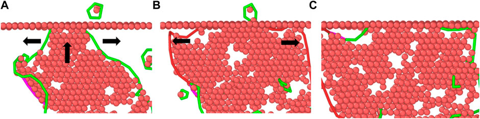
FIGURE 8. Analysis snapshot of twin boundaries hindering the growth of stacking faults. (A) SF grow along the shear direction. (B) SF change the grow direction. (C) The final state of SF.
When the strain reaches 10% or even 15%, more slip systems are activated. Due to the hindrance of the dislocation movement by the twin boundary, the dislocations generate in a large amount, and many immovable dislocations are formed at the twin boundary. The results show that some stacking faults intersect each other, disordered atoms are generated at the intersection, and an amorphous phase is formed. In addition, a part of martensite transformation occurs along the shear direction, which is composed of four layers of FCC atoms. In the process of martensite transformation, it is easy to cause substructures with high lattice defects in the crystal lattice. One part is the high-density dislocations accumulated in the martensite, and the other part may be the twin defects in the martensite, this is also consistent with the rise of the twin density in the plastic phase in Figure 6F.
To further illustrate the evolution of the amorphous phase, the atoms of the nt-HEAs are painted according to the CNA and von Mises (VM) stress value. Whether it is a stacking fault-twin boundary crossing (1 in Figure 9A) or a stacking fault-stacking fault crossing (2 in Figure 9A), the accumulation of dislocations in these two intersection regions will cause local stress concentration. The stress concentration then causes serious disturbance of the lattice in the intersecting region, leading to the destruction of the adjacent crystal structure and the nucleation of the amorphous phase. Zhao et al. (2016) and Wu et al. (2017) have conducted relevant demonstrations through molecular dynamics and experiments. The results show that in the subsequent loading process, the accumulation of dislocations causes an increase in internal stress, which is released by destroying the ordered structure near the amorphous phase, so that the amorphous phase continues to expand (S. Zhao et al., 2021).
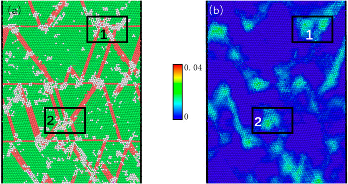
FIGURE 9. The cross-section of microstructure evolution and atomic local stress dispersions, in which the strain is 0.05. (1) Stacking fault-twin boundary crossing. (2) Stacking fault-stacking fault crossing.
Looking at the changes in the nt-HEAs model, it can be observed that the model mainly relies on the interaction of defects and dislocations for plastic deformation. This can also be seen from the evolution of the dislocation density in Figures 6F–K: For the model with a twin spacing of 0.61 and 3.08 nm, the model with a twin spacing of 6.78 nm is not only a steady increase in the intrinsic stacking fault content, but there is also a larger increase in the area where martensitic transformation occurs, while maintaining a higher dislocation density. It can be said that the co-dominant deformation modes such as dislocation slip and stacking faults, secondary twins, and martensite are the main factors that maintain the current plastic state of deformation.
Figure 10 shows the structural snapshots of the nt-HEAs model with a twin spacing of 3.08 nm at different moments. When the strain reaches 0.026, the model dislocation source appears and some Shockley dislocations appear, and the dislocation source is still located between twins.
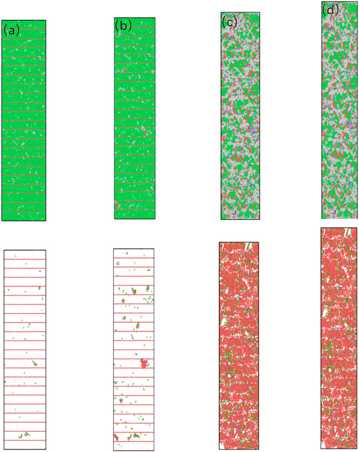
FIGURE 10. The microstructure of nt-HEAs (λ = 3.08 nm) under different strains (A) 2.6%, (B) 3%, (C) 10%, (D) 15%.
As the model continues to be loaded, the stacking faults grow to the twin boundaries and are hindered. Due to the relatively high density of twin boundaries, the ability of twin boundaries to hinder the movement of dislocations is enhanced. Therefore, defects such as stacking faults are more likely to grow to the twin boundaries after dislocation slip. Sessile stair-rod dislocations accumulate at the twin interface, and the dislocation density is significantly higher than the model with low twin density; The martensitic transformation has only a very small part, which means that the closer twin spacing is not suitable for the generation of martensitic transformation. From the comparison of Figures 6E–H, it can be observed that the density of immovable dislocations accumulated in the low-density twin model is lower, which further explains that part of the main reason for the plastic deformation of this model is due to the accumulation of high-density dislocations. Immovable dislocations played an important role in the process. In addition, dislocations accumulate at the twin interface, causing more amorphous phases to be produced.
When the strain reaches 10%, it can be seen that the amorphous phase is easier to nucleate and diffuse due to high-density twins. The amorphous phases in different regions are connected during the diffusion process, and part of the continuous bulk amorphous phase is formed under the interaction. When the strain reaches 15%, the amorphous phase further expands. The increase in the average flow stress of the model is a comprehensive result of the model’s amorphization and dislocation accumulation.
The overall deformation mode is mainly reflected in the increment of the twin density of the twin model. On the one hand, the repulsive force for dislocations close to the twin boundary further increases its yield strength. On the other hand, the twin boundary hinders the nucleation and propagation of dislocations during plastic deformation. The accumulation of immovable dislocations played a more important role, the formation of the amorphous phase and the further expansion of the interaction of the amorphous phase maintain the plastic deformation of the model.
For the model with twin spacing λ = 0.61 nm, the twin spacing is the theoretical minimum twin boundary spacing composed of three atomic layers, and its unique deformation mechanism makes it have the highest yield stress and plasticity and the highest average flow stress. To clarify its deformation mechanism, a snapshot of its structure under different strains and the evolution of dislocation density are shown in Figure 11.
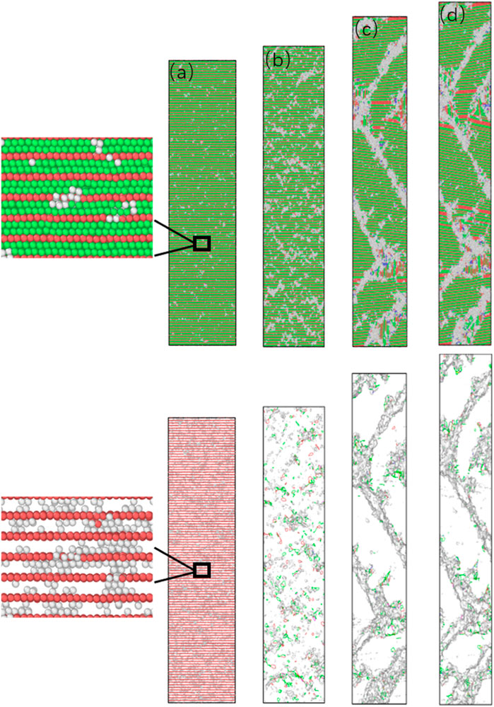
FIGURE 11. The microstructure of nt-HEAs (λ = 0.61 nm) under different strains (A) 2.6%, (B) 3%, (C) 10%, (D) 15%.
From Figure 11A, it can be found that the source of dislocation is still emitted from the middle of the twin boundary, and the twin interface still maintains a relatively stable state, but unlike the low-density twin model, it is not generated by the Shockley Partial dislocation-guided stacking faults and other dislocation defects, ultra-close twin layers no longer support the generation of stacking faults in the shear direction. During the continued loading process, we found that due to the ultra-high density of twin grain boundaries, the initial disordered dislocation source expansion can easily extend to the grain boundaries in one direction to form a small range of amorphous phases, while the two-way expansion can easily combine the two adjacent twin boundaries are connected. As the deformation increases, the amorphized area gradually expands. This indicates that the initiation of the plastic deformation of nt-HEAs, which is composed of the smallest twin boundary spacing, is achieved through lattice distortion. Lattice distortion preferentially nucleates from between the twins, and the continuous growth of the amorphous phase causes the twin boundaries to lose coherence. This is mainly because when the twin boundary distance is reduced to 0.61 nm (3 atomic layer thickness), the repulsive force of the twin boundary for dislocation nucleation and movement has reached or even exceeded the force required for the deformed nucleus of the lattice. Therefore, nt-HEAs can only produce a lot of lattice distortion with high critical stress during plastic deformation, so this model presents the highest yield strength. As the loading continues, a large number of small amorphous phases continue to diffuse, and when two small amorphous phases meet, they connect to form a large amorphous phase along the shear direction, as shown in the shadow defect in Figure 11D.
When the strain reaches 10%, it is found that the amorphous phase has been connected along the shear direction into a bulk amorphous phase similar to the grain boundary, which has played a role in grain refinement; In the process of the formation of the amorphous phase, the accumulation of part of the small amorphous phase also makes the crystal orientation of the small crystal grains tilt. When the strain reaches 15%, the amorphous region further expands.
Why can the ultra-high density twin boundary distance model maintain higher flow stress? In order to further explore the influence of the tensile process on the performance of the ultra-high-density twin model from the perspective of crystal structure, an atomic-scale analysis consisting of atomic shear strain distribution and local stress was carried out. The atomic shear strain distributions and local stress distributions of the model when the strain is 10 and 15% are shown in Figure 12. The atoms of the model are drawn based on the values of von Mises shear strain and volumetric stress.
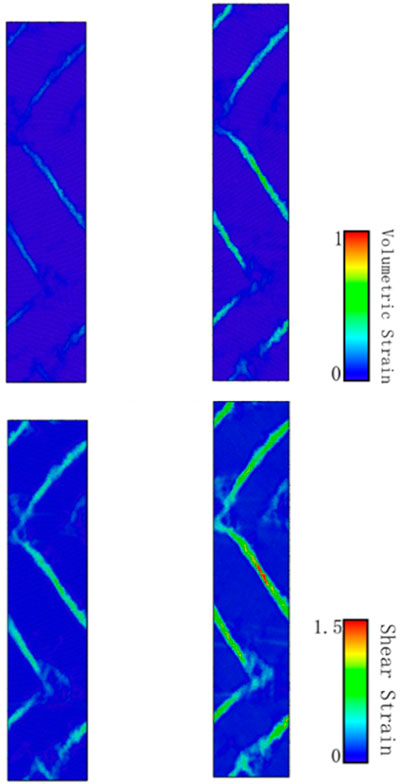
FIGURE 12. The cross-section of atomic shear strain distributions and volumetric stress at strain of 10%, 15%.
It can be found that with the tensile loading process, whether it is the shear stress distribution or the local volume stress, these two key factors are mainly acting on the changes in the disordered grain boundaries. What is interesting is that the high average flow stress of the ultra-high density twin boundary proposed by Shen et al. (2021) is mainly strengthened by martensite transformation. In Figure 6G, we have carried out relevant calculations in the plane stacking fault density and found that although a part of martensitic transformation does occur during the stretching process, in the process of calculating the local shear stress and the local volume stress. The martensitic transformation did not show its prominent influence.
In addition, the reason for the formation of martensite transformation in the ultra-high density twin model (λ = 0.61 nm) is different from that in the model with lower twin density (λ = 6.78 nm). The martensite transformation in the ultra-high-density twin model is based on the sliding of two adjacent FCC atomic layers when the small amorphous phase moves, so the martensite formed is along the twin boundary direction. The role of stretching in the vertical direction is relatively small; while the martensite in the low-density twin model is formed based on the adjacent SF-SF movement in the shear direction. This kind of martensite based on the shear direction provides a relatively higher contribution due to the plastic deformation process of the nt-HEAs. The atomic snapshots of the martensite formation process and the martensite transformation mechanism of the two different cases are shown in Figure 13.
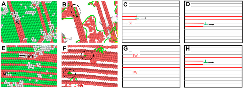
FIGURE 13. Analysis snapshot of MT phase transition of the nt-HEAs with the twin boundary spacing of 6.78 nm (A–D) and 0.61 nm (E–H) (CNA analysis diagram on the left and DXA analysis diagram on the right).
Figure 14 shows the cross-sectional view of the atomic displacement vectors of the ultra-high-density twins at strains of 10 and 15%. The displacement vector is very effective in defining the position changes of the atoms during the stretching process. When tensile loading, due to the uneven amorphous phase, the atoms on both sides of the amorphous phase are stretched and move asymmetrically along the y-axis direction. One side of the atom moves upward, and the other side moves downward. This can also explain why part of the twin boundary is tilted. In addition, it shows that GB blocks and changes the direction of atom displacement. It can also be seen that the grain boundary hinders the movement of atoms. As the displacement vector of atoms near the grain boundary is larger, and the atomic displacement vector inside the crystal grain is small, it is also explained from the perspective of atomic displacement that the grain boundary plays a more important role in the plastic deformation process.
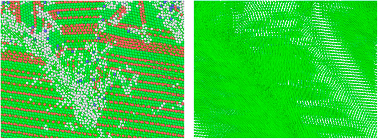
FIGURE 14. The cross-sectional view of the displacement vectors of atoms under tension loading at strain of 10 and 15%.
In this paper, molecular dynamics simulation methods are used to study the mechanical behavior of nt-HEAs under tensile load, and the effect of the twin boundary distance λ on the mechanical properties and deformation mechanism of nt-HEAs is systematically analyzed. The main conclusions are:
1. There is a Hall–Petch relationship with the distance between twin boundaries, and there is a critical value (3.08 nm) for the strengthening effect of nt-HEAs by the distance between twin boundaries. The relationship makes the sensitivity of the yield strength to the twin boundary spacing change before and after the critical value. The reason is that the decreasing twin spacing is no longer suitable for the growth of large complete stacking faults, which changes the deformation mechanism of the low twin spacing model.
2. In the process of plastic deformation, nt-HEAs with λ ≥ 3.08 nm produces a large number of dislocations and forms plugging at the twin boundaries. The strengthening of the dislocation accumulation leads to high flow stress. The results show that stacking faults, secondary twins and martensitic transformation also provide some support for deformation. As the distance between twin boundaries decreases, the number of dislocations generated during the deformation of nt-HEAs becomes less and less, and the role of amorphization in its plastic deformation process gradually appears.
3. When λ < 0.61 nm, the plastic deformation of nt-HEAs is dominated by amorphization caused by lattice distortion, accompanied by martensitic transformation, which is different from the martensitic transformation in the conventional sense. Here, the martensitic transformation is caused by its special twin spacing. With the decrease of the twin boundary spacing, the major deformation mechanism of nt-HEAs has changed from dislocation slip to the amorphous phase. The results obtained in this paper can provide advanced scientific predictions and useful references for the design of high-performance high-entropy alloys.
The raw data supporting the conclusion of this article will be made available by the authors, without undue reservation.
LZ designed experiments, carried out experiments, and analyzed experimental results, wrote the manuscript. HX designed experiments, carried out experiments, and analyzed experimental results. DZ designed experiments, and analyzed experimental results. ZL designed experiments. SM designed experiments.
Project supported by the National Natural Science Foundation of China (Grant No. 11602158). Project supported by the National Natural Science Foundation of ShanXi Province, China (Grant No. 201901D111088). Project supported by the National Natural Science Foundation of China (Grant No. 11972244).
The authors declare that the research was conducted in the absence of any commercial or financial relationships that could be construed as a potential conflict of interest.
All claims expressed in this article are solely those of the authors and do not necessarily represent those of their affiliated organizations, or those of the publisher, the editors and the reviewers. Any product that may be evaluated in this article, or claim that may be made by its manufacturer, is not guaranteed or endorsed by the publisher.
We gratefully acknowledge the support from the National Natural Science Foundation of China (Grant No. 11602158), the National Natural Science Foundation of China (Grant No. 11972244), and the National Natural Science Foundation of ShanXi province, China (Grant No. 201901D111088).
Afkham, Y., Bahramyan, M., Mousavian, R. T., and Brabazon, D. (2017). Tensile Properties of AlCrCoFeCuNi Glassy Alloys: A Molecular Dynamics Simulation Study. Mater. Sci. Eng. A 698, 143–151. doi:10.1016/j.msea.2017.05.057
Chen, W., Fu, Z., Fang, S., Xiao, H., and Zhu, D. (2013). Alloying Behavior, Microstructure and Mechanical Properties in a FeNiCrCo0.3Al0.7 High Entropy alloy. Mater. Des. 51, 854–860. doi:10.1016/j.matdes.2013.04.061
Chuang, M.-H., Tsai, M.-H., Wang, W.-R., Lin, S.-J., and Yeh, J.-W. (2011). Microstructure and Wear Behavior of AlxCo1.5CrFeNi1.5Tiy High-Entropy Alloys. Acta Materialia 59 (16), 6308–6317. doi:10.1016/j.actamat.2011.06.041
Doan, D.-Q., Fang, T.-H., and Chen, T.-H. (2020). Influences of Grain Size and Temperature on Tribological Characteristics of CuAlNi Alloys under Nanoindentation and Nanoscratch. Int. J. Mech. Sci. 185, 105865. doi:10.1016/j.ijmecsci.2020.105865
Dong, Q., Chen, Z., Wang, C., Zhou, K., and Wei, J. (2021a). Partial Slip Contact of Materials with Vertically Aligned Cracks Near Surface. Eng. Fracture Mech. 245, 107557. doi:10.1016/j.engfracmech.2021.107557
Dong, Q., Chen, Z., Zhou, K., and He, D. (2021b). Fretting Contact of Layered Materials with Vertical Cracks Near Surfaces. Int. J. Mech. Sci. 198, 106361. doi:10.1016/j.ijmecsci.2021.106361
Faken, D., and Jónsson, H. (1994). Systematic Analysis of Local Atomic Structure Combined with 3D Computer Graphics. Comput. Mater. Sci. 2 (2), 279–286. doi:10.1016/0927-0256(94)90109-0
Farkas, D., and Caro, A. (2020). Model Interatomic Potentials for Fe-Ni-Cr-Co-Al High-Entropy Alloys. J. Mater. Res. 35 (22), 3031–3040. doi:10.1557/jmr.2020.294
Fourmont, A., Le Gallet, S., Politano, O., Desgranges, C., and Baras, F. (2020). Effects of Planetary ball Milling on AlCoCrFeNi High Entropy Alloys Prepared by Spark Plasma Sintering: Experiments and Molecular Dynamics Study. J. Alloys Comp. 820, 153448. doi:10.1016/j.jallcom.2019.153448
Guo, X., and Xia, Y. (2011). Repulsive Force vs. Source Number: Competing Mechanisms in the Yield of Twinned Gold Nanowires of Finite Length. Acta Materialia 59 (6), 2350–2357. doi:10.1016/j.actamat.2010.12.031
Hirel, P. (2015). Atomsk: A Tool for Manipulating and Converting Atomic Data Files. Comp. Phys. Commun. 197, 212–219. doi:10.1016/j.cpc.2015.07.012
Kumar, N., Ying, Q., Nie, X., Mishra, R. S., Tang, Z., Liaw, P. K., et al. (2015). High Strain-Rate Compressive Deformation Behavior of the Al0.1CrFeCoNi High Entropy alloy. Mater. Des. 86, 598–602. doi:10.1016/j.matdes.2015.07.161
Li, J., Chen, H., Li, S., Fang, Q., Liu, Y., Liang, L., et al. (2019). Tuning the Mechanical Behavior of High-Entropy Alloys via Controlling Cooling Rates. Mater. Sci. Eng. A 760, 359–365. doi:10.1016/j.msea.2019.06.017
Li, J., Fang, Q., Liu, B., Liu, Y., and Liu, Y. (2016). Mechanical Behaviors of AlCrFeCuNi High-Entropy Alloys under Uniaxial Tension via Molecular Dynamics Simulation. RSC Adv. 6 (80), 76409–76419. doi:10.1039/C6RA16503F
Lu, K., Lu, L., and Suresh, S. (2009). Strengthening Materials by Engineering Coherent Internal Boundaries at the Nanoscale. Science 324 (5925), 349–352. doi:10.1126/science.1159610
Ma, S. G., Zhang, S. F., Gao, M. C., Liaw, P. K., and Zhang, Y. (2013). A Successful Synthesis of the CoCrFeNiAl0.3 Single-Crystal, High-Entropy Alloy by Bridgman Solidification. JOM 65 (12), 1751–1758. doi:10.1007/s11837-013-0733-x
Saito, T., Furuta, T., Hwang, J.-H., Kuramoto, S., Nishino, K., Suzuki, N., et al. (2003). Multifunctional Alloys Obtained via a Dislocation-free Plastic Deformation Mechanism. Science 300 (5618), 464–467. doi:10.1126/science.1081957
Sharma, A., and Balasubramanian, G. (2017). Dislocation Dynamics in Al0.1CoCrFeNi High-Entropy alloy under Tensile Loading. Intermetallics 91, 31–34. doi:10.1016/j.intermet.2017.08.004
Shen, T.-Z., Song, H.-Y., and An, M.-R. (2021). Effect of Twin Boundary on Mechanical Behavior of Cr26Mn20Fe20Co20Ni14 High-Entropy alloy by Molecular Dynamics Simulation. Acta Phys. Sin. 70 (18), 186201. doi:10.7498/aps.70.20210324
Shun, T.-T., and Du, Y.-C. (2009). Microstructure and Tensile Behaviors of FCC Al0.3CoCrFeNi High Entropy alloy. J. Alloys Comp. 479 (1–2), 157–160. doi:10.1016/j.jallcom.2008.12.088
Song, H. Y., and Sun, Y. (2015). Effect of Coherent Twin Boundary and Stacking Fault on Deformation Behaviors of Copper Nanowires. Comput. Mater. Sci. 104, 46–51. doi:10.1016/j.commatsci.2015.03.052
Stukowski, A., Bulatov, V. V., and Arsenlis, A. (2012). Automated Identification and Indexing of Dislocations in crystal Interfaces. Model. Simul. Mater. Sci. Eng. 20 (8), 085007. doi:10.1088/0965-0393/20/8/085007
Stukowski, A. (2014). Computational Analysis Methods in Atomistic Modeling of Crystals. JOM 66 (3), 399–407. doi:10.1007/s11837-013-0827-5
Stukowski, A. (2010). Visualization and Analysis of Atomistic Simulation Data with OVITO-The Open Visualization Tool. Model. Simul. Mater. Sci. Eng. 18 (1), 015012. doi:10.1088/0965-0393/18/1/015012
Tadmor, E. (2004). A First-Principles Measure for the Twinnability of FCC Metals. J. Mech. Phys. Sol. 52 (11), 2507–2519. doi:10.1016/j.jmps.2004.05.002
Thompson, A. P., Aktulga, H. M., Berger, R., Bolintineanu, D. S., Brown, W. M., Crozier, P. S., et al. (2022). LAMMPS - a Flexible Simulation Tool for Particle-Based Materials Modeling at the Atomic, Meso, and Continuum Scales. Comp. Phys. Commun. 271, 108171. doi:10.1016/j.cpc.2021.108171
Wang, W.-R., Wang, W.-L., Wang, S.-C., Tsai, Y.-C., Lai, C.-H., and Yeh, J.-W. (2012). Effects of Al Addition on the Microstructure and Mechanical Property of AlxCoCrFeNi High-Entropy Alloys. Intermetallics 26, 44–51. doi:10.1016/j.intermet.2012.03.005
Wu, W., Ni, S., Liu, Y., Liu, B., and Song, M. (2017). Amorphization at Twin-Twin Intersected Region in FeCoCrNi High-Entropy alloy Subjected to High-Pressure Torsion. Mater. Characterization 127, 111–115. doi:10.1016/j.matchar.2017.02.027
Xiao, J., and Deng, C. (2020). Continuous Strengthening in Nanotwinned High-Entropy Alloys Enabled by Martensite Transformation. Phys. Rev. Mater. 4 (4), 043602. doi:10.1103/PhysRevMaterials.4.043602
Yan, S., H Qin, Q., and Zhong, Z. (2020). On the Real-Time Atomistic Deformation of Nano Twinned CrCoFeNi High Entropy alloy. Nanotechnology 31 (38), 385705. doi:10.1088/1361-6528/ab99ef
Yan, Z., and Lin, Y. (2019). Lomer-Cottrell Locks with Multiple Stair-Rod Dislocations in a Nanostructured Al alloy Processed by Severe Plastic Deformation. Mater. Sci. Eng. A 747, 177–184. doi:10.1016/j.msea.2019.01.066
Yeh, J.-W., Chen, S.-K., Lin, S.-J., Gan, J.-Y., Chin, T.-S., Shun, T.-T., et al. (2004). Nanostructured High-Entropy Alloys with Multiple Principal Elements: Novel Alloy Design Concepts and Outcomes. Adv. Eng. Mater. 6 (5), 299–303. doi:10.1002/adem.200300567
Zhao, S., Hahn, E. N., Kad, B., Remington, B. A., Wehrenberg, C. E., Bringa, E. M., et al. (2016). Amorphization and Nanocrystallization of Silicon under Shock Compression. Acta Materialia 103, 519–533. doi:10.1016/j.actamat.2015.09.022
Zhao, S., Li, Z., Zhu, C., Yang, W., Zhang, Z., Armstrong, D. E. J., et al. (2021). Amorphization in Extreme Deformation of the CrMnFeCoNi High-Entropy alloy. Sci. Adv. 7 (5), eabb3108. doi:10.1126/sciadv.abb3108
Keywords: high-entropy alloy, molecular dynamics, mechanical behavior, twin boundary density, deformation mechanism
Citation: Zhang L, Xin H, Zhao D, Li Z and Ma S (2022) Effect of Twin Boundary Density on Mechanical Behavior of Al0.1CoCrFeNi High-Entropy Alloy by Molecular Dynamics Simulation. Front. Mater. 9:849051. doi: 10.3389/fmats.2022.849051
Received: 05 January 2022; Accepted: 08 February 2022;
Published: 03 March 2022.
Edited by:
Mohsen Asle Zaeem, Colorado School of Mines, United StatesReviewed by:
Roghayeh Mohammadzadeh, Azarbaijan Shahid Madani University, IranCopyright © 2022 Zhang, Xin, Zhao, Li and Ma. This is an open-access article distributed under the terms of the Creative Commons Attribution License (CC BY). The use, distribution or reproduction in other forums is permitted, provided the original author(s) and the copyright owner(s) are credited and that the original publication in this journal is cited, in accordance with accepted academic practice. No use, distribution or reproduction is permitted which does not comply with these terms.
*Correspondence: Hao Xin, eGluaGFvQHR5dXQuZWR1LmNu; Dan Zhao, emhhb2RhbkB0eXV0LmVkdS5jbg==
Disclaimer: All claims expressed in this article are solely those of the authors and do not necessarily represent those of their affiliated organizations, or those of the publisher, the editors and the reviewers. Any product that may be evaluated in this article or claim that may be made by its manufacturer is not guaranteed or endorsed by the publisher.
Research integrity at Frontiers
Learn more about the work of our research integrity team to safeguard the quality of each article we publish.