 Luo Chunyu1
 Jia Zhengpeng
- 1Road Tunnel Branch of Sichuan Highway Bridge Construction Group Co., Ltd., Chengdu, Sichuan, China
- 2Civil Engineering, The Southwest Jiaotong University, Chengdu, Sichuan, China
- 3Faculty of Geosciences and Environmental Engineering, The Southwest Jiaotong University, Chengdu, Sichuan, China
Based on the finite element limit analysis method, the stability of the face in case of active failure under three constitutive models, the Mohr-Coulomb model (MC), the modified Cambridge model (MCC) and the Drucker-Prager model (DP), were analyzed. The ultimate support pressure of the face and the influence of factors such as different burial depth ratios (C/D), cohesion (c) and friction angle (φ) in the MC model are also discussed. The results show that the safety factor obtained by the MCC model under the same support pressure is always smaller than that of the MC model, and the difference is the largest when there is no support pressure. As the support pressure increases, it will gradually approach the MC model. When the support pressure is small, the safety factor obtained by the DP model is larger than the MC model, but when the support pressure is large, it is smaller than the MC model, and the final difference tends to be stable. It is necessary to select an appropriate constitutive model according to different rock masses in practical engineering. The self-stabilizing performance of the face is not affected by C/D, and the ultimate support pressure will increase with the increase of C/D, decrease linearly with the increase of cohesion, and decrease with the increase of friction angle. When the friction angle is small, the ultimate support pressure is greatly affected by C/D, and when the friction angle is large, it is hardly affected by C/D.
1 Introduction
The development of underground space in cities has become a trend with the rapid growth of urban rail transportation in China. The current shield construction technology is one of the leading engineering methods for urban underground tunnel construction (Sui et al., 2021) the shield excavation process, the support on the tunnel face is the guarantee to maintain the stability of the tunnel. When the support pressure is too small, the tunnel will collapse, and when the support pressure is too enormous the ground surface will bulge (Zamora Hernández et al., 2019). Therefore, how to solve the ultimate support pressure more accurately has become a sensitive research topic for most scholars.
In the early days, the stability of the tunnel face after tunnel excavation was studied by empirical formulas and simple qualitative or quantitative analysis (Broms and Bennermark, 1967). However, these methods were relatively crude in the calculation. Subsequently, the limit equilibrium method and the limit analysis method were rapidly developed for geotechnical applications (He et al., 2019a; He et al., 2019b; He et al., 2021; He et al., 2022) and were also widely used in the stability analysis of tunnel faces and could be used to find out the ultimate support pressure of tunnel faces (Chen, 1975; Davis et al., 1980; Comejo, 1989; Leca and Dormieus, 1990; Mollon et al., 2010; Han et al., 2016; Lu et al., 2017). However, these two methods have many assumptions that make it difficult to solve complex problems. The emergence of finite element methods have brought new solvers to geotechnical issues (Sloan and Assadi, 1991; Wilson et al., 2011; Zheng et al., 2012; He et al., 2019c; Shiau Al-Asadi, 2020), and with the development of computer and numerical computation technology, various numerical simulation software has become more and more widely used, and not only finite element numerical software such as ABAQUS, ANSYS, FLAC 3D and OPTUM G2 have been used for stability analysis of tunnel faces (Do et al., 2014; Li and Li, 2019; Zamora Hernández et al., 2019; Huang et al., 2020; Zheng et al., 2022), but many discrete element numerical software is also maturing and being used in the study of geotechnical properties (Bai et al., 2022).
The Mohr-Coulomb constitutive model (MC model) is mainly used in the above tunnel face stability analysis (Ji et al., 2021; Feng et al., 2022), which is popular among scholars and engineers because of its simple and practical features, and as research progresses, more and more Constitutive models are proposed and gradually used in the stability analysis of tunnel faces (Bai et al., 2019; Bai et al., 2021). The Mohr-Coulomb model considers that the compression modulus and rebound modulus of the soil are the same, and there are some cases where the Mohr-Coulomb model is not applicable, and it is necessary to select a suitable constitutive model according to different tunneling conditions. Zhao et al. (2015) used the HSS model to simulate the shield supported mechanized excavation of the Western Scheldt tunnel in the Netherlands. Keawsawasvong and Ukritchon, (2020) used the Hoek-Brown model to develop a new design equation for stability analyses of shallow unlined circular tunnels in rock masses. Liu et al. (2020) used the DP model to present a semi-analytical solution as well as finite element numerical simulations for the tunnel excavation problem. Fang et al. (2022) used a number of constitutive models to account for initial soil anisotropy and non-coaxial plasticity, which were confirmed in a field investigation through the Tsinghua Park Tunnel of the Beijing-Zhang High Speed Railway in China.
Therefore, this paper discusses the stability of the tunnel face under active failure calculated with three constitutive models and solves for the ultimate support pressure, and discusses the effects of parameters such as burial depth ratio C/D and cohesion c, friction angle φ.
2 Constitutive model
2.1 Mohr-coulomb model (MC)
The MC model is very widely used in geotechnical analysis nowadays. It is not only a relatively simple model, but more importantly is that all of its parameters have direct physical meaning and can be measured by conventional tests such as direct shear and triaxial tests. The principal stresses σ1 and σ3 are used to represent the yield surface (as shown in Figure 1) as a function of
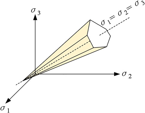
FIGURE 1. MC yield surface in principal stress space.
In order to avoid explicit calculation of principal stresses, Nayak and Zienkiewicz (Nayak and Zienkiewicz, 1972) proposed to use the following variables based on the stress tensor principle:
which
The MC model is controlled by the elastic modulus E and Poisson’s ratio υ for elastic deformation, and the cohesion c, friction angle φ and shear expansion angle ψ for plastic deformation.
2.2 Modified cam-clay model (MCC)
The Cambridge model was constructed by Roscoe and Burland (Roscoe and Burland, 1968); in 1968 and was later modified and refined for the analysis of elastic-plastic deformation of clay soils (both consolidated and superconsolidated). A slightly extended version of this model was implemented according to the scheme proposed by Krabbenhoft (Krabbenhoft and Lyamin, 2012), and the yield surface (as shown in Figure 2) functioned as:
which

FIGURE 2. MCC yield surface in the q-
Where the superscripts of the variables indicate the effective stress and pc is the prior consolidation pressure. The MCC model is controlled by the parameters of compression index λ, resilience index κ, initial pore ratio e0, cohesion c and friction angle φ, all of which can be obtained experimentally.
2.3 Drucker-Prager model (DP)
Drucker-Prager modified the Mises criterion to propose a new yielding criterion for the damage analysis of rocks with the yield surface shown in Figure 3. The projection in the π-plane is the inner tangent circle of the MC yield surface projection shown in Figure 4, and the yield function is expressed as
which
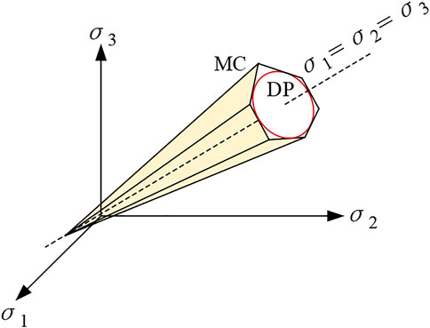
FIGURE 3. MC and DP yield surfaces in principal stress space.
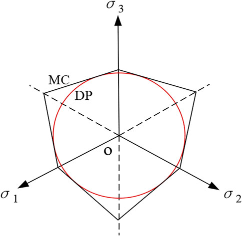
FIGURE 4. MC and DP yield surfaces in the π plane.
Where the parameters M and k are constants related to the soil friction angle φ and cohesion c respectively. To ensure that the soil material parameters match the numerical calculations and to consider the associated flow rule, the DP model and MC model parameters can be equivalently transformed by the following equation.
3 Ultimate support pressure analysis at the tunnel face
In this paper, the stability of the tunnel face is analyzed by three methods: finite element limit analysis, finite difference method and limit analysis upper limit method, and the ultimate support pressure on the tunnel face is obtained.
Based on the OPTUM G2 (Finite Element Limit Analysis) and FLAC (Finite Difference Method) platforms. To simplify the analysis, the median plane of the 3D tunnel is intercepted, and a two-dimensional analysis is carried out considering the plane strain problem, as shown in Figure 5. The tunnel diameter D is 8 m. In order to ignore the influence of boundary conditions as far as possible, the length of the tunnel extension below L1 = 8 m, the longitudinal length of the tunnel L2 = 16 m, and the length of the model extension in the horizontal direction L3 = 16 m. The entire bottom boundary of the model is fully constrained, and the left and right boundaries of the model and the upper and lower boundaries inside the tunnel are constrained normally to each other.
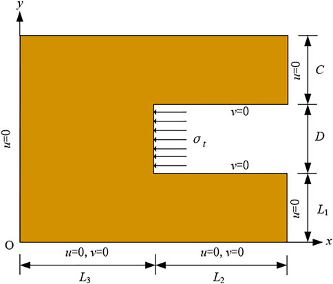
FIGURE 5. Stability analysis model of tunnel face.
Meanwhile, this paper adopts the multi-block damage model of the tunnel face proposed by Yang Feng (Yang et al., 2010), as shown in Figure 6; the red line in the figure indicates the damaged surface, based on the theory of limit analysis upper limit method, construct the constraint and objective function and use the non-linear solver fmincon in MATLAB to program the ultimate support pressure of the tunnel face can be found, the specific solution process and calculation formulae are shown in the literature (Nayak and Zienkiewicz, 1972).
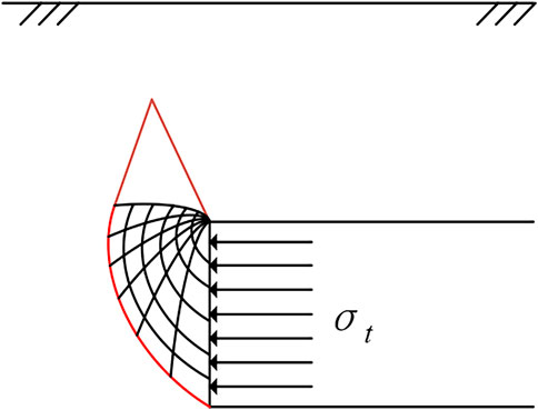
FIGURE 6. Failure model of shallow tunnel face.
Where the soils have a weight of 20 kN/m3 and a cohesive force of 10 kPa, calculations were carried out using the Mohr-Coulomb yielding constitutive model. The variation of the ultimate support pressure with friction angle at the tunnel face for two working conditions (C/D = 1, C/D = 2) was explored using the three methods mentioned above, and the results are shown in Figures 7, 8.
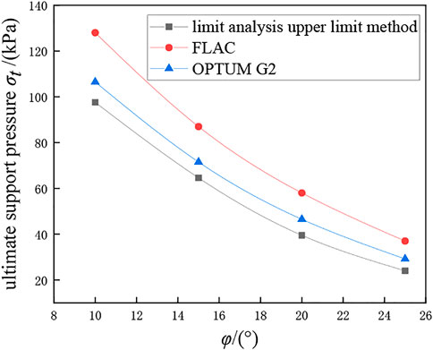
FIGURE 7. When C/D = 1 in MC model, the ultimate support pressure varies with friction.
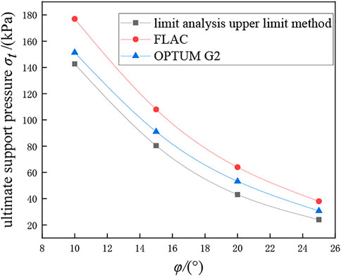
FIGURE 8. When C/D = 2 in MC model, the ultimate support pressure varies with friction.
During the analysis, the simulation of the working conditions at different C/D was controlled only by changing the thickness C of the overburden layer, while other values were kept constant. It can be seen from Figures 7, 8 that the ultimate support pressure at the tunnel face decreases as the friction angle increases, and the larger the C/D, the greater the ultimate support pressure required. All three calculation methods show the same variation pattern, and the results are close to each other, with the limit analysis upper limit method being more dangerous, FLAC (finite difference method) being more conservative, and OPTUM G2 (finite element limit analysis method) being in between and the tunnel face damage pattern (shown in Figure 9) is consistent with the damage pattern used in the limit analysis upper limit method (shown in Figure 6) hence this method is used consistently in the subsequent discussions of the constitutive model analysis.
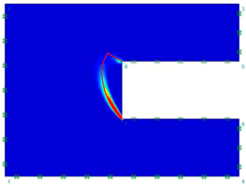
FIGURE 9. C/D = 1 finite element limit analysis calculation of the failure mode of the tunnel face.
4 Analysis of different constitution models
4.1 Model building
In order to analyze the effect of different constitutive models on the ultimate support pressure at the tunnel face, the three constitutive models mentioned in Section 1 were used for the analysis: i) the ideal elastoplastic constitutive Mohr-Coulomb model (MC); ii) the Modified Cambridge model (MCC), which reflects the elastic-plastic damage of soft soils well; and iii) the Drucker-Prager model (DP), which reflects the elastic-plastic damage of rocks. The calculation method was selected from the finite element limit analysis method used in the previous section.
Refer to Figure 5 for a geometric model of the tunnel with geometric parameters taken from the literature (Yuan et al., 2021), where the diameter of the tunnel D is 9 m, the extension length below L1 = 9 m, the longitudinal length L2 = 18 m, and the horizontal extension length L3 = 18 m.
4.2 Soil parameters
The soil parameters in the tunnel model were taken from the literature (Yuan et al., 2021) and the values of the soil parameters for the three constitutive models are shown in Tables 1–Tables 3. where the natural weight of the soil γ = 18 kN/m3 and the associated flow rule was used for the calculation.
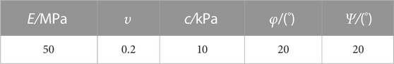
TABLE 1. The calculation parameters of MC model.
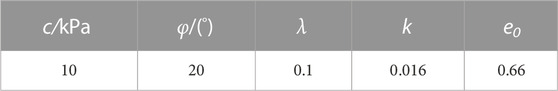
TABLE 2. The calculation parameters of MCCmodel.
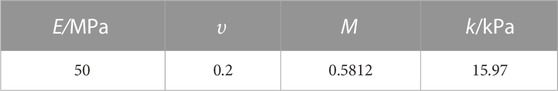
TABLE 3. The calculation parameters of DP model.
5 Analysis of results
Based on the finite element limit analysis and strength reduction method, this paper analyses the stability of the tunnel face under three different constitutive models and discusses the effect of varying burial depth ratios C/D on the ultimate support pressure.
5.1 Analysis of the results of different constitution models
Considering two working conditions with C/D is 1 and 1.5, calculate the variation of safety factor with support pressure at the tunnel face under three constitutive models (see Figure 10).
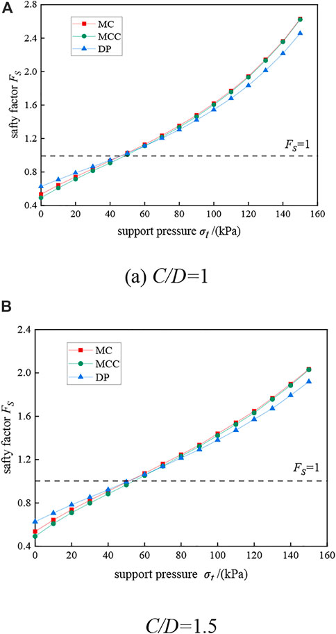
FIGURE 10. The safety factor varies with support pressure under different constitutive conditions. (A) C/D = 1, (B) C/D = 1.5.
It can be seen from Figure 10 that the factor of safety increases with the increase in support pressure regardless of the working conditions or the constitutive model (only active damage is considered). For the same support pressure, the safety factor obtained with the MC model is always slightly higher than that of the MCC model; when the safety factor is less than 1, the safety factor obtained with the DP model is greater than that of the MC and MCC models for the same support pressure, but when the required safety factor is greater than 1, the safety factor calculated with the DP model is less than that of the MC model (this is consistent with the fact that the yield surface of the DP model is tangent to the yield surface of the MC model). The ultimate support pressures (safety factor equal to 1) obtained with the MC and DP models are almost identical, while the ultimate support pressures obtained with the MCC model are relatively large.
To reflect the influence of different constitutive models on the stability of the tunnel face more intuitively, the percentage difference in the safety factor under different constitutive models (compared with the MC model) is discussed, and the burial depth ratio C/D is taken as 1 for calculation, and the results are shown in Figure 11.
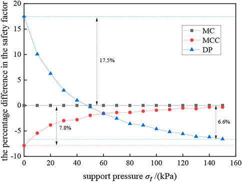
FIGURE 11. Percentage of safety factor gap when C/D = 1.
The positive sign in Figure 11 indicates that the result is larger than that calculated by the MC model, and the negative sign indicates that it is smaller. It can be seen that the safety coefficient calculated by the MCC model is smaller than that of the MC model under the same support pressure, and the difference is the largest when the support pressure is not considered, which is 7.8% smaller than that of the MC. The coefficient of safety at the intersection of the DP model and the MC model is 1, indicating that the ultimate support pressure under the MC model and the DP model is the same. When the support pressure is small, the coefficient of safety obtained under the DP model is larger than that under the MC model, and the difference is the largest when the support pressure is not considered, with a value of 17.5%. The difference tends to stabilize and gradually converges to 6.6% in this paper.
5.2 Analysis of C/D results for different burial depth ratios
In the discussion of the previous section, it was found that the burial depth ratio C/D has a greater effect on the ultimate support pressure, so the effect of the C/D ratio on the stability of the tunnel face and the ultimate support pressure under active failure was further investigated, and the results are shown in Figure 12.
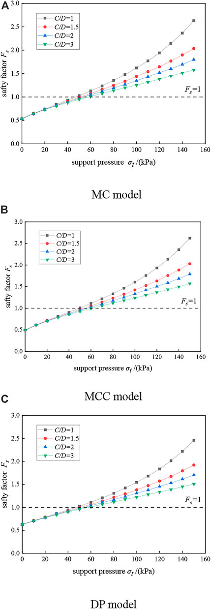
FIGURE 12. Variation of safety factor with support pressure under different C/D. (A) MC model, (B) MCC model, (C) DP model.
When the support pressure is zero, the coefficient of safety obtained from different C/D is almost the same, indicating that the self-stabilizing performance of the tunnel face is almost independent of C/D. As the support pressure increases, the smaller the C/D the greater the coefficient of safety, and the greater the coefficient of safety is influenced by the support pressure (the slope of the curve in the graph). And the greater the C/D, the greater the ultimate support pressure obtained and the more dangerous the tunnel face is.
6 Analysis of MC model strength parameters
The MC model was selected in order to analyze the influence of the strength parameters of the soil on the ultimate support pressure at the tunnel face further. The tunnel geometry model constructed in Section 3.1 was used to explore the influence of the friction angle c and cohesion φ on the ultimate support pressure at the tunnel face in the MC model based on the finite element limit analysis method, and the influence of four different C/D working conditions was also analyzed, and the calculation results are shown in Figure 13.
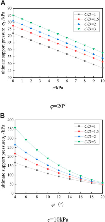
FIGURE 13. Influence of MC model parameters on ultimate support pressure under different C/D conditions. (A) φ=20°, (B) c=10 kPa.
It can be seen that the ultimate support pressure at the tunnel face decreases with the increase of cohesion, and presents a linear relationship, the larger the C/D, the greater the ultimate support pressure, and the ultimate support pressure-viscosity curve under different C/D conditions is approximately parallel; the ultimate support pressure also decreases with the increase of friction angle, presenting a non-linear relationship, and finally tends to a stable value. When the friction angle is small, it is influenced by C/D, however, when the friction angle is large, it is almost independent of C/D, and the ultimate support pressure under different C/D is close to the same.
7 Conclusion
This paper adopts the finite element limit analysis method to establish a two-dimensional tunnel face model, analyses the stability of the tunnel face under three different constitutive models, and solves for the ultimate support pressure, taking into account the effects of parameters such as burial depth ratio, cohesion and friction angle in the MC model. And leading to the following conclusions:
(1) Compared to the MC model, the safety factor obtained by the MCC model for the same support pressure is always smaller than that of the MC model, with a maximum difference of 7.8% when there is no support pressure, but gradually converges to that of the MC model as the support pressure increases. This shows that the MCC model is more conservative than the MC model.
(2) Compared to the MC model, the DP model gives a greater safety factor than the MC model when the support pressure is small and 17.5% greater than the MC model when there is no support pressure; however, when the support pressure is large, the safety factor is less than the MC model and the final difference leveled off at 6.6%.
(3) The larger the C/D, the greater the required ultimate support pressure of the tunnel face. When the support pressure is not considered, the safety coefficients under different C/D calculations are the same, which means that the self-stabilizing performance of the tunnel face is almost independent of C/D. When the support pressure is greater, the smaller the C/D is the greater the influence.
(4) The ultimate support pressure at the tunnel face decreases linearly with the increase of cohesion, and the curves of the ultimate support pressure with cohesion are approximately parallel to each other at different burial depth ratios C/D. The larger the friction angle is, the higher the friction angle is, the ultimate support pressure at the tunnel face decreases non-linearly with the friction angle and finally tends to a stable value. When the friction angle is small, the ultimate support pressure is more influenced by C/D, and when the friction angle is large, it is less influenced by C/D. At this time, the ultimate support pressure under different C/D is almost the same.
Data availability statement
The datasets presented in this study can be found in online repositories. The names of the repository/repositories and accession number(s) can be found in the article/supplementary material.
Author contributions
LC: Investigation, Software, Validation, Data curation, Funding acquisition, Supervision, Writing—original JZ: draft, Conceptualization, Methodology, Resources, Visualization, Writing—original draft. LZ: Supervision, Conceptualization, Writing—review and editing. XK: Funding acquisition, Data curation, Writing—review and editing. WB: Data curation, Writing—review and editing.
Funding
This study was supported by the Natural Science Foundation of Sichuan Province (2022NSFSC0407) and the Sichuan Science and Technology Funding Scheme: Seismic Instability Mechanism and Stability Evaluation of Mixed Earth and Rock Slopes in Deep Canyon Areas on the Southeast Rim of the Qinghai-Tibet Plateau (2021YFH0037).
Conflicts of interest
Authors LC was employed by the company Road Tunnel Branch of Sichuan Highway Bridge Construction Group Co., Ltd.
The remaining authors declare that the research was conducted in the absence of any commercial or financial relationships that could be construed as a potential conflict of interest.
Publisher’s note
All claims expressed in this article are solely those of the authors and do not necessarily represent those of their affiliated organizations, or those of the publisher, the editors and the reviewers. Any product that may be evaluated in this article, or claim that may be made by its manufacturer, is not guaranteed or endorsed by the publisher.
References
Bai, B., Wang, Y., Rao, D., and Fan, B. (2022). The effective thermal conductivity of unsaturated porous media deduced by pore-scale SPH simulation. Front. Earth Sci. 10, 943853. doi:10.3389/feart.2022.943853
Bai, B., Yang, G., Tao, L., and Yang, G. (2019). A thermodynamic constitutive model with temperature effect based on particle rearrangement for geomaterials. Mech. Mater. 139, 103180. doi:10.1016/j.mechmat.2019.103180
Bai, B., Zhou, R., Cai, G., Hu, W., and Yang, G. (2021). Coupled thermo-hydro-mechanical mechanism in view of the soil particle rearrangement of granular thermodynamics. Comput. Geotechnics 137 (8), 104272. doi:10.1016/j.compgeo.2021.104272
Broms, B. B., and Bennermark, H. (1967). Stability of clay at vertical opening. J. Soil Mech. Found. Div. ASCE 96 (1), 71–94. doi:10.1061/jsfeaq.0000946
Comejo, L. (1989). Instability at the face: Its repercussions for tunneling technology [J]. Tunn. tunnlgV21 26(5), 69–74.
Davis, E. H., Gunn, M. J., Mair, R. J., and Seneviratine, H. N. (1980). The stability of shallow tunnels and underground openings in cohesive material. Géotechnique 30, 397–416. doi:10.1680/geot.1980.30.4.397
Do, N., Dias, D., Oreste, P., and Djeran-Maigre, I. (2014). Three-dimensional numerical simulation of a mechanized twin tunnels in soft ground. Tunn. Undergr. Space Technol. 42, 40–51. doi:10.1016/j.tust.2014.02.001
Fang, Y., Cui, J., Wanatowski, D., Nikitas, N., Yuan, R., and He, Y. (2022). Subsurface settlements of shield tunneling predicted by 2D and 3D constitutive models considering non-coaxiality and soil anisotropy: A case study. Can. geotechnical J. 59 (3), 424–440. doi:10.1139/cgj-2020-0620
Feng, X., Wang, P., Liu, S., Wei, H., Miao, Y., and Bu, S. (2022). Mechanism and law analysis on ground settlement caused by shield excavation of small-radius curved tunnel. Rock Mech. rock Eng. 55 (6), 3473–3488. doi:10.1007/s00603-022-02819-6
Han, K., Zhang, C., and Zhang, D. (2016). Upper-bound solutions for the face stability of a shield tunnel in multilayered cohesive–frictional soils. Comput. geotechnics 79, 1–9. doi:10.1016/j.compgeo.2016.05.018
He, Y., Liu, Y., Hazarika, H., and Yuan, R. (2019a). Stability analysis of seismic slopes with tensile strength cut-off. Comput. geotechnics 112, 245–256. doi:10.1016/j.compgeo.2019.04.029
He, Y., Liu, Y., Zhang, Y., and Yuan, R. (2019b). Stability assessment of three-dimensional slopes with cracks. Eng. Geol. 252, 136–144. doi:10.1016/j.enggeo.2019.03.001
He, Y., Wang, X., Yuan, R., Liu, K. W., and Zhuang, P. Z. (2019c). On the computational precision of finite element algorithms in slope stability problems. J]. Math. problems Eng. 2019, 1–15. doi:10.1155/2019/9391657
He, Y., Yu, J., Yuan, R., Wang, W., and Nikitas, N. (2022). Stability and failure mechanisms in three-dimensional cracked slope: Static and dynamic analysis. Comput. geotechnics 144, 104626. doi:10.1016/j.compgeo.2021.104626
He, Y., Yu, J., Yuan, R., and Yong, F. (2021). Stability analysis of the soil slope with cracks considering the upper slope inclination[J]. China J. Highw. Transp. 34 (05), 45–54. (In Chinese). doi:10.19721/j.cnki.1001-7372.2021.05.005
Huang, Z., Zhang, C., Fu, H., Deng, H., Ma, S., and Fu, J. (2020). Numerical study on the disturbance effect of short-distance parallel shield tunnelling undercrossing existing tunnels. Adv. Civ. Eng. 2020, 1–14. doi:10.1155/2020/8810658
Ji, J., Zhang, Z., Wu, Z., Xia, J., Wu, Y., and Lu, Q. (2021). An efficient probabilistic design approach for tunnel face stability by inverse reliability analysis. Geosci. Front. 12 (5), 101210. doi:10.1016/j.gsf.2021.101210
Keawsawasvong, S., and Ukritchon, B. (2020). Design equation for stability of shallow unlined circular tunnels in Hoek-Brown rock masses. Bull. Eng. Geol. Environ. 79 (8), 4167–4190. doi:10.1007/s10064-020-01798-8
Krabbenhoft, K., and Lyamin, A. V. (2012). Computational Cam clay plasticity using second-order cone programming. Comput. Methods Appl. Mech. Eng. 209, 239–249. doi:10.1016/j.cma.2011.11.006
Leca, E., and Dormieus, L. (1990). Upper and lower bound solutions for the face stability of shallow circular tunnels in frictional material. Géotechnique 40, 581–606. doi:10.1680/geot.1990.40.4.581
Li, B., and Li, H. (2019). Prediction of tunnel face stability using a naive bayes classifier. Appl. Sci. 9 (19), 4139. doi:10.3390/app9194139
Liu, K., Chen, S., and Xiaoqiang, G. (2020). Analytical and numerical analyses of tunnel excavation problem using an extended drucker–prager model. Rock Mech. rock Eng. 53 (4), 1777–1790. doi:10.1007/s00603-019-01992-5
Lu, X., Zhou, Y., Huang, M., and Li, F. (2017). Computation of the minimum limit support pressure for the shield tunnel face stability under seepage condition. Int. J. Civ. Eng. 15 (6), 849–863. doi:10.1007/s40999-016-0116-0
Mollon, G., Dias, D., and Soubra, A. (2010). Face stability analysis of circular tunnels driven by a pressurized shield. J. geotechnical geoenvironmental Eng. 136 (1), 215–229. doi:10.1061/(asce)gt.1943-5606.0000194
Nayak, G. C., and Zienkiewicz, O. C. (1972). Convenient form of stress invariants for plasticity. J. Struct. Div. ASCE 98 (98), 949–954. doi:10.1061/jsdeag.0003219
Roscoe, K. H., and Burland, B. (1968). On the generalised stress-strain behaviour of an ideal wet clay[C]. HEYMAN, LECKIE. Engineering Plasticity. Cambridge: Cambridge University Press, 535–609.
Shiau, J., and Al-Asadi, F. (2020). Two-dimensional tunnel heading stability factors F, F and F. Tunn. Undergr. space Technol. 97, 103293. doi:10.1016/j.tust.2020.103293
Sloan, S. W., and Assadi, A. (1991). Undrained stability of a square tunnel in a soil whose strength increases linearly with depth. Comput. Geotechnics 12 (4), 321–346. doi:10.1016/0266-352x(91)90028-e
Sui, H., Ma, C., Dai, C., and Yang, T. (2021). Study on stability of shield tunnel excavation face in soil-rock composite stratum. Math. problems Eng. 2021, 1–19. doi:10.1155/2021/5579103
Wilson, D. W., Abbo, A. J., Sloan, S. W., and Lyamin, A. V. (2011). Undrained stability of a circular tunnel where the shear strength increases linearly with depth. Can. Geotechnical J. 48 (9), 1328–1342. doi:10.1139/t11-041
Yang, F., Yang, J., and Zhao, L. (2010). Collapse mechanism and support pressure for shallow tunnel face [J]. Chin. J. Geotechnical Eng. 32 (2), 279–284. (In Chinese). doi:10.16285/j.rsm.2015.01.035
Yuan, R., Xiong, W., and He, Y. (2021). Analysis on the law of ground settlement in shallow tunnel excavation in camposite layered strata[J]. J. Southwest Jiaot. Univ. 40 (9), 1000–1005. In Chinese. doi:10.3969/j.issn.0258-2724.20210473
Zamora Hernández, Y., Durand Farfán, A., and Pacheco De Assis, A. (2019). Three-dimensional analysis of excavation face stability of shallow tunnels. Tunn. Undergr. space Technol. 92, 103062. doi:10.1016/j.tust.2019.103062
Zhao, C., Lavasan, A. A., Barciaga, T., Zarev, V., Datcheva, M., and Schanz, T. (2015). Model validation and calibration via back analysis for mechanized tunnel simulations – the Western Scheldt tunnel case. Comput. geotechnics 69, 601–614. doi:10.1016/j.compgeo.2015.07.003
Zheng, G., Fan, Q., Zhang, T., and Zhang, Q. (2022). Numerical study of the Soil-Tunnel and Tunnel-Tunnel interactions of EPBM overlapping tunnels constructed in soft ground. Tunn. Undergr. space Technol. 124, 104490. doi:10.1016/j.tust.2022.104490
Keywords: railway tunnel, constitutive model, numerical calculation, stable tunnel face, ultimate support pressure
Citation: Chunyu L, Zhengpeng J, Zhi L, Kefeng X and Bohan W (2023) Analyses on face stability of shallow tunnel considering different constitutive models. Front. Mater. 9:1112425. doi: 10.3389/fmats.2022.1112425
Received: 30 November 2022; Accepted: 15 December 2022;
Published: 04 January 2023.
Edited by:
Bing Bai, Beijing Jiaotong University, ChinaReviewed by:
Yang Lu, Sichuan University, ChinaWen Nie, Jiangxi University of Science and Technology, China
Copyright © 2023 Chunyu, Zhengpeng, Zhi, Kefeng and Bohan. This is an open-access article distributed under the terms of the Creative Commons Attribution License (CC BY). The use, distribution or reproduction in other forums is permitted, provided the original author(s) and the copyright owner(s) are credited and that the original publication in this journal is cited, in accordance with accepted academic practice. No use, distribution or reproduction is permitted which does not comply with these terms.
*Correspondence: Jia Zhengpeng, NTUzNDExNDY5QHFxLmNvbQ==