 Rui Yu1
 Wenhang Li
95% of researchers rate our articles as excellent or good
Learn more about the work of our research integrity team to safeguard the quality of each article we publish.
Find out more
ORIGINAL RESEARCH article
Front. Mater. , 04 January 2023
Sec. Mechanics of Materials
Volume 9 - 2022 | https://doi.org/10.3389/fmats.2022.1080981
This article is part of the Research Topic Design and Mechanical Failure of Deep-Sea Pressure Structures View all 6 articles
With the fast-growing demand of aluminum alloys in ships and deep-sea pressure structures, an accurate and efficient underwater cutting operation for aluminum alloy is significant. However, its underwater arc cutting mechanism is still not clear enough, which limits its further application. The challenges lie in poor underwater visibility and complex underwater environment. In this study, process experiments, underwater sensor, and numerical simulations were conducted during cutting process to investigate the cutting mechanism of 5,052 aluminum. Firstly, the effect of parameters were investigated on cutting current, voltage, and water depth on the underwater kerf formation. In addition, three typical kerf formations, including “V” type, “II” type and “∧” type, were found; Secondly, visual sensing system was setup to monitor the cutting arc trajectory and the combustion process during the cutting process. Specially, the underwater burning phenomenon was observed. Finally, Finite Element Analysis was performed to further analyze the underwater arc cutting kerf formation of aluminum alloy. A semi-ellipsoidal composite heat source was applied to simulate the underwater arc, and the aluminum thermal reaction-generated heat was introduced. A dynamic method named “birth and death elements” was utilized to simulate the removal of molten metal. The temperature test results show that the simulation process is feasible. All results showed that different cutting parameters led to different cutting mode and affected the kerf forming. 5,052 aluminum alloy in the deep water environment (≥50 m) kerf significantly narrowed. The kerf cross-section produces an inward concavity and the kerf surface is as wide as the cutting wire. The aluminum kerf forming process is greatly impacted by the process parameters and self-propagating high-temperature synthesis reaction during aluminum alloy cutting. The periodicity of the cutting process was computed by the numerical simulation with the arc motion trajectory monitored by the high-speed camera. The numerical results of temperature distribution and kerf shape were consistent with the experimental data, which revealed the cutting mechanism.
With the fast-growing demand of aluminum alloys in ships and deep-sea pressure structures, an accurate and efficient underwater cutting operation for aluminum alloy is significant. In the presence of hydrostatic pressure, deep-sea pressure structures are prone to instability, which is significantly influenced by geometry, materials, and defects. Underwater cutting technology is required for underwater pressure structures disassembly and maintenance. (Parshin et al., 2021a)Flux-cored arc cutting (FCAC) technology has been proven to be efficient, safe, and cost-efficient, but the research on aluminum alloys is inadequate. Therefore, to improve the aluminum alloys cutting efficiency, reduce energy consumption, and control the formation of the kerf, it is necessary to study the aluminum alloys underwater cutting mechanism.
As a type of underwater wet cutting, FCAC provides gas through the flux-cored cutting wire to keep the arc burning under water. Unlike other underwater cutting methods, it works without additional oxygen supply equipment. (Parshin et al., 2021b) Parton Welding Institute (Paton Electric Welding Institute, 2007) conducted the pioneering process research on FCAC. Manual cutting has high quality, but it is not feasible for large-scale application. Automatic underwater cutting, on the other hand, requires in-depth understanding of the cutting process. Research on the cutting process was expanded. However, the underwater cutting process easily produces turbidity, and the effect of parameters is usually assessed by observing the kerf formation after cutting (Świerczyńska et al., 2017). The findings indicate that the cutting process is significantly influenced by the cutting current, cutting voltage, cutting speed, and water depths, but most of the above researches were conducted on carbon steel.
Various sensors were studied to better understand the cutting process including arc sensor, visual sensor, and sound sensor. Arc sensor is resistant to underwater arc interference. Masanobu (Masanobu, 1982) counted the current and voltage distribution during underwater cutting to determine the arc stability. Their research revealed that the underwater cutting procedure was unstable and the cutting arc alternately extinguished and burned during cutting. To determine the quality of cutting, Parshin have provided a criterion based on the ratio of the voltage probability density in the idle and operating cycles. (Parshin et al., 2021c) However, the arc sensor was not able to monitor the cutting process or to detect the cutting depth as the arc would go out when the cut bottom declined. Underwater vision sensor is important but must overcome the challenge of water turbidity and bubbles fluctuation. (Li et al., 2019a) The arc position of underwater cutting is different from underwater welding, during which the welding arc burns on the surface of the workpiece. Therefore (Li et al., 2019b), investigated the arc behavior in a sandwich structure, but the arc position can only be determined vaguely and the cutting formation pattern of the whole workpiece is not explainable. (Jia et al., 2019) utilized high-speed cameras and (Xu et al., 2019) utilized X-ray to monitor the underwater welding metal transfer, spatter (Guo et al., 2015), bubble growth (Yang et al., 2019), and other processes, as a way to explore the welding process stability and forming process. (Guo et al., 2019) Unfortunately, these two visual sensing methods cannot be applied to the underwater cutting process. In underwater cutting, the cutting wire is extended inside the workpiece and the arc burns inside the kerf, making it invisible through the workpiece.
Since the aluminum alloy underwater cutting process is not observable, a numerical simulation model is established based on experimental data 64to study the kerf formation process. Most research on underwater cutting simulation focus on laser cutting or plasma cutting (Kim et al., 2022), and there are few researches on underwater arc cutting. Surrounding water impacts the arc as well as the workpiece cooling process, which is critical to the simulation of the underwater arc cutting process. (Wang et al., 2017) simulated the cutting procedure with a predetermined cutting, which does not reflect the randomness of the cutting edge. Therefore, it is required to conduct a simulation of kerf formation in a dynamic manner.
This paper reveals the mechanism of underwater flux-cored arc cutting of 5,052 aluminum alloy. The remainder of the paper is organized as follows. First, the underwater cutting process of the aluminum alloy under different parameters was studied. Second, the underwater arc cutting trajectory was monitored with visual sensing. Third, the ANSYS software is utilized to simulate the temperature field of the cutting process and the heat changes during the cutting process are discussed while optimizing the process parameters. Finally, the aluminum alloy kerf forming rules under different process parameters are obtained, and the simulation is verified based on visual sensing.
The FCAC experimental system was set up to study the underwater arc cutting procedure, as shown in Figure 1. The experimental platform mainly consists of the cutting process experimental system and the arc and visual sensing system. The experimental system’s composition is comparable to that of the GMAW except for the shielding gas. The cutting power source was Panasonic KR500, which was operated with a constant wire feed speed and in DC constant-voltage mode. The self-shielded PPR-AN2 flux-cored wire with a diameter of 2.0 mm was made in Paton Electric Welding Institute of Ukraine. The dimensions of the 5,052 aluminum alloy cutting piece were 900 mm (length)×400 mm (width)×16 mm (thickness). These devices can be placed in a pressure vessel filled with water to imitate various water depths for cutting in order to modify the depth of the water. The cutting process was analyzed by changing the cutting speed, arc voltage and cutting current (wire feed speed).
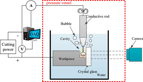
FIGURE 1. Underwater arc cutting system.
The base metal prepared for this experiment is a 5,052 series aluminum alloy with each chemical element composition as shown in Table 1. The cutting wire consists mainly of peroxide, carbonate and other gas-forming components.

TABLE 1. 5,052 aluminum alloy content of each element.
In order to understand the effects of different process factors, one factor was changed at a time during the cutting process. The experimental parameters are shown in Table 2 These factors include the water depth, cutting current (adjusted by changing the wire feed speed), arc voltage, and cutting speed.
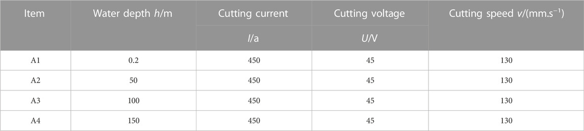
TABLE 2. Underwater cutting test parameters.
As shown in Figure 2, the water depth has a significant effect on the kerf formation. When the water depth is larger than 0.2 m, it is apparent that the kerf width becomes much narrower beyond 50 m water depth.
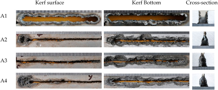
FIGURE 2. Effects of water depth on cutting quality.
When the water depth increases, it is considered that the arc is compressed in the radial direction due to water pressure and other factors, resulting in a narrower kerf cross-section. Additionally, the kerf’s inward concave in the cross-section is clearly visible. This is also caused by an increase in water pressure, which lengthens the cutting time inside the workpiece and causes heat accumulate at the center of the kerf. While the kerf bottom is mainly cut by heat conduction and arc blowing force, the kerf bottom becomes narrower and forms an inner concavity.
The experimental parameters are shown in Table 3. When the water depth environment is fixed, the variation of the cutting current has less effect on the kerf formation as shown in Figure 3. As shown on the kerf surface, larger cutting current results in circular variations of the kerf.
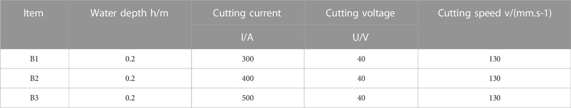
TABLE 3. Underwater cutting test parameters.

FIGURE 3. Effects of current on cutting quality.
Compared to the Low-carbon steel cutting, the aluminum alloy features the thermite reaction, resulting in easier cut of the workpiece and wider kerf. The generated heat accelerates metal melting and removal of the molten metal from the kerf bottom. During the cutting process, the high heat release causes the molten metal to splatter and produce a sparking airburst.
The cutting voltage significantly affects the kerf formation. The experimental parameters are shown in Table 4. The width of the kerf surface narrows dramatically as the cutting voltage drops. The cutting wire must enter the workpiece deeply because of the shorter arc length and lower voltage. As can be seen from the cross-section corresponding to 30V, the kerf surface is primarily cut by heat conduction and short-circuit arc, therefore the width of the kerf is comparable to the width of the cutting wire, as shown in Figure 4.
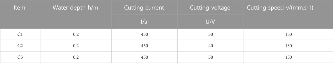
TABLE 4. Underwater cutting test parameters.
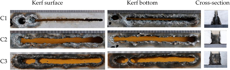
FIGURE 4. Effects of voltage on cutting quality.
Compared with the change of other cutting parameters, the effect of cutting speed on the kerf is limited. With the increase in cutting speed, the sidewall of the cutting wire touches the front of the kerf more frequently, hence minimizing the occurrence of arc extinguishment. However, because of the increased cutting speed, the cutting arc stays a shorter duration at the kerf. These effects reduce the cutting capacity, narrow the kerf, and even prevent cutting through. In general, the increase in cutting speed leads to a decrease in the kerf width.
According to the above experiments, 5,052 aluminum alloy underwater cutting experiments found three typical kerf formations, including “V" type, “II” type and "∧" type, as shown in Figure 5. Each mode corresponds to a different current-voltage cutting process.
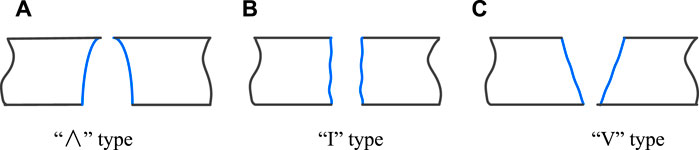
FIGURE 5. Typical kerf forming of aluminum alloy. (A)"∧" type; (B)"I" type; (C)"V" type.
Figure 6 shows the underwater burning phenomenon distinguishes the underwater aluminum alloy cutting with the carbon steel cutting. A color camera was used to capture the comparative images of underwater cutting of both aluminum alloy and carbon steel. The arc light in the photograph is white, while the flame is yellow. When aluminum alloy starts to arc, there is always a flame burning in the water. Even if the arc is extinguished, the flame will continue to burn. In contrast to the Q235 cutting process, there was no visible flame, and the image was filled with white arcs.

FIGURE 6. Colored camera photographing underwater cutting. (1) Underwater arc cutting 5052 aluminum alloy; (2) Underwater arc cutting Q235 low carbon steel.
The reaction of the aluminum alloy cutting process is related to the self-propagating high-temperature synthesis technology by analyzing the cutting process. The arc temperature is substantially higher than that of the aluminum alloy’s ignition. The arc heat ignites the workpiece, which then automatically spreads to the cutting area until the reaction is finished. Most of the workpiece impurities are vaporized during the combustion process, which improves the kerf formation quality. The arc blowing force expels the cutting slag from the kerf, minimizing flaws such slag clinging on the aluminum alloy cutting edge. This also results in instability throughout the entire aluminum alloy cutting process, making it challenging to control and measure the procedure. Therefore, the Fourier heat transfer equation can be used to calculate the heat of reaction:
Here: Cp is the product heat capacity, p is the product density, k is the product thermal conductivity, q is the heat of reaction, T is the absolute temperature, t is time, and x is the dimension of the wave propagation direction.
The whole cutting process was monitored by high-speed camera during the experiments. According to the arc trajectory and kerf shape in Figure 7, the cutting arc is a circular motion from surface to bottom. When cutting through the bottom of the workpiece, the arc is extinguished. The cutting process has the phenomenon of arc extinguishing-arc restarting. When the cutting wire contacts the cutting edge, the arc is reset. The cutting torch continues to move in the cutting direction while arc extinguished.
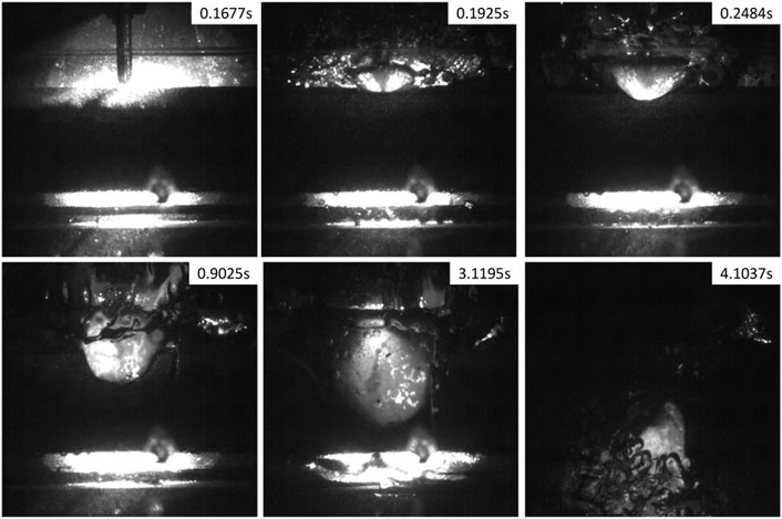
FIGURE 7. Underwater cutting arc movement trajectory.
As the underwater cutting process cannot be clearly captured by these cameras, the cutting arc-visual sensing method is difficult to show the underwater cutting mechanism. It is necessary to investigate the mechanism of underwater cutting process with numerical simulation techniques combined with the observed results. The key to the simulation of underwater cutting is the boundary conditions brought by water, the regularity of the motion of the heat source, and the implementation of molten metal removal. According to the characteristics of underwater cutting experiments, a numerical model was established to simulate the underwater cutting process.
The model is based on the actual component. As seen in Figure 8, the model is symmetrical with regard to the Y-Z plane. The temperature field analysis can only be performed on half of the workpiece. It can not only reduce the calculation time but also visually observes changes in the cut. The X-axis is in the width direction; the Y-axis is in the cutting direction and the z-axis is in the thickness direction.
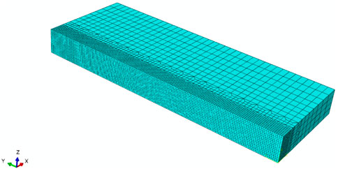
FIGURE 8. Cutting workpiece meshing model.
The kerf position is heated directly and the edge of the workpiece is heated up by heat transfer. The entire workpiece’s temperature fluctuates drastically.
These elements near the kerf had a compact structure-the size was 0.5 mm × 0.5 mm × 0.5 mm. The elements far away from kerf get gradually arc sparse. The initial temperature was 20°C.
The cooling rate of the workpiece under water is different from that on land. Since the arc burns within the workpiece, heat transfer occurs inside the kerf and the inner wall of the kerf does not set water cooling boundary conditions. Thermal radiation and convection are carried out through the outer surface of the workpiece, and water-cooled boundary conditions are set for the workpiece surface. The radiative heat transfer coefficient hr of the specimen can be calculated using the following equation.
where σ is the Boltzmann constant equal to 5.67 × 10⁻⁸, ε is the metal emissivity, an intrinsic property equal to 0.8, T is the surface temperature of the specimen, and T0 is the water temperature and is about 10°C at that time.
Cp(s), Cp(1) are the constant pressure specific heat capacities of the solid and liquid phases of the product, respectively, Tm is its melting point, and ΔHm is the latent heat of melting.
It is assumed that chemical reactions and convection in the molten pool are ignored, as well as vaporization during water contact. The convection of the cutting process is used to change the cooling rate. Meanwhile, bubbles generated by arc combustion carry a lot of heat away, resulting in a rapid temperature drop. The boiling heat transfer problem significantly altered the convective heat transfer coefficient between water and the workpiece. According to the boiling heat exchange principle of water, the APDL language is used to set the convection heat transfer coefficient of water and workpiece. The formula for the convective heat transfer coefficient is provided below:
When the temperature difference ΔT between the workpiece and the water is large, the water convection coefficient is small. The convection coefficient grows fast as the temperature difference diminishes. When the temperature approaches 200°C, the convection coefficient reaches its maximum and then decreases rapidly. Each time the arc moves downwards, the inner wall of the kerf is exposed to the water and the surface of the workpiece. The underwater environment’s thermal boundary conditions are determined by the underwater convection heat transfer coefficient.
Different from the commonly used double ellipsoid heat source for welding, this research uses a semi-elliptical heat source k (J. Goldak et al., 1984) for simulation. This research simulates using a semi-elliptical heat source. In actual cutting, the arc is continuously directed downward, and the heat accumulates under the workpiece. Since the kerf is flushed by water and no heat accumulates in the tail of the forward direction, the double ellipsoid heat source was not used.
The water environment has a complex effect on the cutting arc. (Li et al., 2018). The first is that the aquatic environment has a significant cooling effect compared to the air; and the second is that the underwater cutting arc’s shape and energy density dramatically change under the pressure of the water. The underwater arc gets compressive as water depth grows and the heat source model’s loading size diminishes. The change in arc energy was characterized by the ratio of the three parameters: ah, bh, and ch.
Where ƞ is the heat efficiency; U and I stand for the cutting current and arc voltage; ɑh, bh, ch describe the semi-axes of the double ellipsoid.
The entire cutting process was regarded as N periodic processes of a heat source from top to bottom. From the number of extinction and some other characteristics of the signal waveforms for current and voltage, the specific value of N can be calculated. The heat source speed in the cutting direction was the same as the actual experimental results. The heat source sink speed in the thickness direction (Z-axis) depended on the current and wire feed speed.
In the simulation, this process causes the heat source to go to the bottom of the workpiece and then jump back to the top along the Y-axis. In each period the position of the heat source was adjusted as time proceeded to achieve the heat source periodic sinking in the Z-axis direction. Figure 9 shows the cutting heat source motion trajectory model.
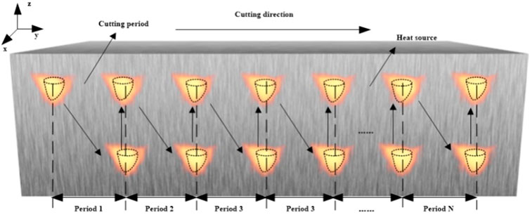
FIGURE 9. Cutting heat source motion trajectory model.
The “birth and death” method was usually applied to simulate the adding of molten metal in welding. In other words, some element on the workpiece was killed by the arc heat and reactivated after it had passed. In cutting process, similar method was utilized to simulate the removal of molten metal. Some elements were alive, and others were killed after the arc heat passed. Because the unstable cutting process generates irregular kerfs, it is impossible to predefine “molten metal elements”. As shown in Figure 10, a dynamic method is used to simulate the removal of molten metal in the following steps:
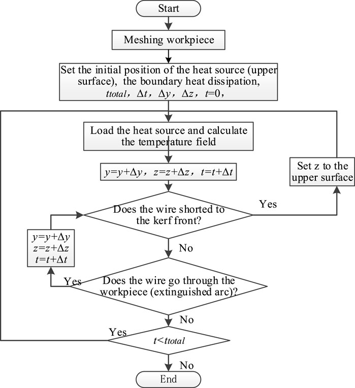
FIGURE 10. Re-modeling flowchart.
Firstly, the workpiece is modeled and meshed, the initial heat source location is set to the upper surface. The parameters include: Actual cutting time t, Total cutting time ttotal (100s), and Calculated time step ∆t (0.2s). The heat source (wire end) moves ∆y in the cutting direction and ∆z in the thickness direction within ∆t. The cutting time is set according to the walking time in the direction of the workpiece thickness (z-axis).
Secondly, the heat source is loaded and the temperature field is calculated. All nodes within the semi-ellipsoidal heat source are selected and heated by transient thermal loads to the nodes. As mentioned above, the dynamic “birth and death” method was used in “melted” process. The temperature field is calculated each ∆t time. After each calculation, the nodes whose temperatures are higher than the melting point, were considered melted and were killed.
Finally, the boundary conditions are updated to simulate the newly exposed inner wall of the kerf after cutting. The heat source movement and node temperature calculations are repeated in each cutting step. These steps repeated until the cutting process end, and the killed elements make up the cutting kerf. The APDL language is used to cycle this process. This method can be used to match the actual cutting speed basically.
To verify of the above simulation method, special nodes near the cutting kerf were measured, as shown in Figure 11. 8 K-type thermocouples were spot-welded into the hole of the work piece for the measurement of temperature, as shown in Figure 11A. (Zhao et al., 2020) To prevent water’s interference in measurement, the thermocouples were isolated from water by glue and plastic pipe. The holes’ locations were 10 mm away from the cutting center line and the distance between the neighboring holes was 10 mm. The diameter of each hole was 3 mm, while the depth of the holes was alternately arranged at 5 mm and 10 mm in turn. According to the process experiment results, the cutting parameter has a great impact on the kerf formation. Therefore, the underwater cutting process at different voltages was simulated, and the process parameters are shown in Table 4.
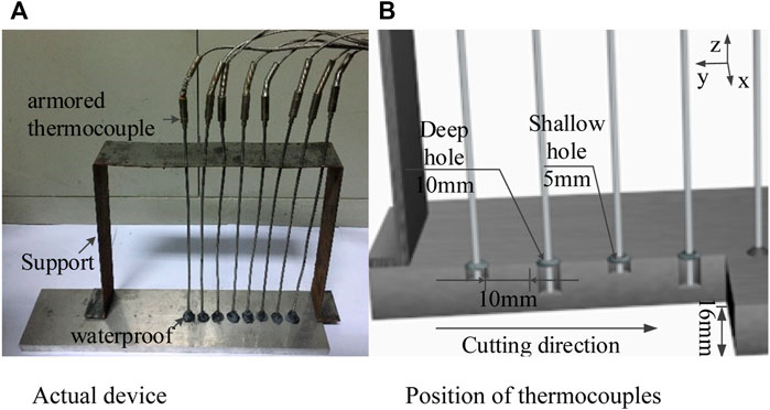
FIGURE 11. Work piece and position of thermocouples. (A) Actual device; (B) Position of thermocouples.
The kerf shape represents the slow transformation of a series of cut holes into a lengthy kerf. Both arc width and length diminish as the cutting voltage decreases. The surface width is proportional to the arc width. The kerf surface width is equal to the diameter of the cut wire because the cut wire must extend into the workpiece to cut the plate. The simulation process is shown in Figure 12.
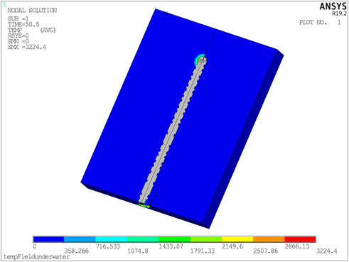
FIGURE 12. Numerical simulation of the cutting process schematic.
Since the simulation results of the periodic heat source are consistent with the experimental results in the kerf formation, the underwater cutting mechanism was verified. Figure 13 depicts the simulation of the temperature field and the kerf formation during the underwater cutting process. During underwater cutting, the heat source moves periodically from top to bottom; 4s–6s is the second cutting cycle. It showed that the metal was removed from the cutting position in the previous cycle.
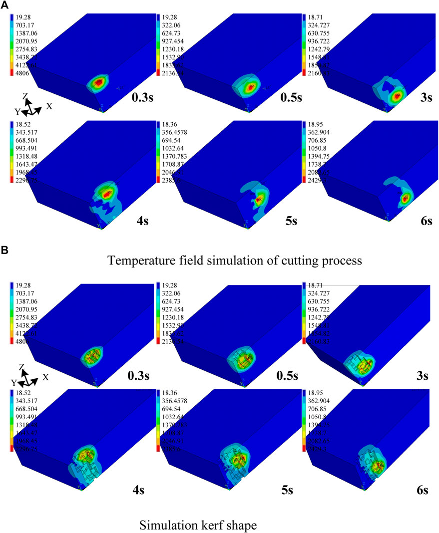
FIGURE 13. Temperature field of the workpiece in one cutting cycle. (A) Temperature field simulation of cutting process; (B) Simulation kerf shape.
We compared the underwater thermal cycle curves to figure out the trend so as to understand the law of heat source movement. Due to the instability of underwater cutting arc combustion, we chose a set of temperature data from each experimental group for comparison.
Some thermocouples were burnt out due to the uncertainty of the cutting process. Figure 14 shows a number of valid thermocouple readings. The numerical simulation results were in good agreement with the measured temperature data in terms of the temperature trend, the maximum temperature and the temperature difference between deep hole and shallow hole.
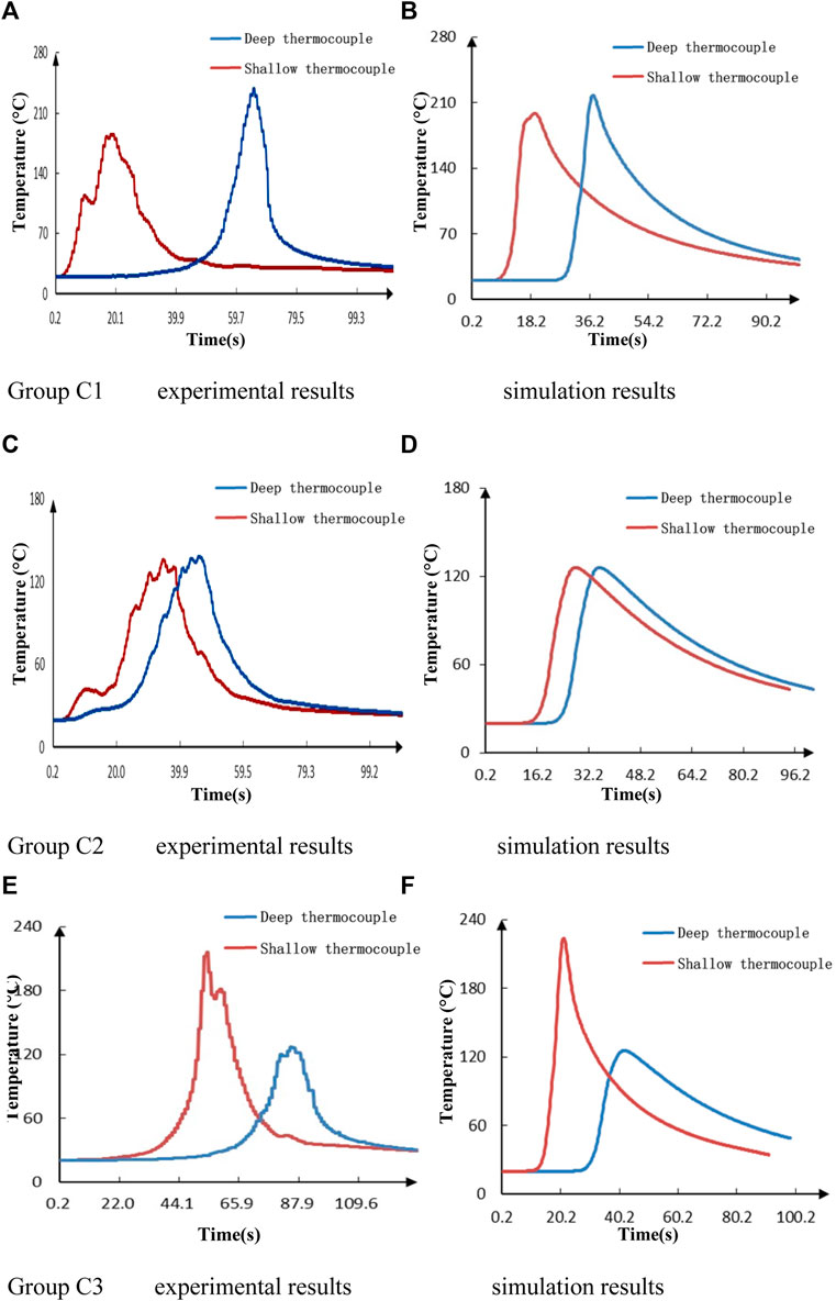
FIGURE 14. Comparison of thermal cycle curves between experimental and simulation. (A) Group C1 experimental results; (B) Group C1 simulation results; (C) Group C2 experimental results; (D) Group C2 simulation results; (E) Group C3 experimental results; (F) Group C3 simulation results.
The peak temperature of the deep hole is higher than that of the shallow hole, as seen in Figure 14 Group C1, as the arc penetrates depth is highest in the workpiece at 30V. The heat accumulation in the deep hole position makes the workpiece melt and warm significantly, allowing the"∧" type kerf shapes to form. Group C3 shows the opposite situation where the cutting arc is mainly located in the upper part of the workpiece while the bottom is only cut by arc blowing force and heat conduction. In Group 2, the cutting current and voltage are well matched with little temperature difference, resulting in “II” type kerf pattern.
Experimental results show that there may also be a tiny peak near the temperature peak. The combustion reaction is still going on after the arc heat source leaves the temperature measurement point, but the water environment quickly extinguishes the combustion flame, resulting in these small temperature peaks. However, the overall trend of the curve remains the same, confirming the periodic motion law of the heat source for flux-cored wire underwater cutting.
The main conclusions of this study are as follows:
1) In shallow water environment (0.2 m), when the cutting voltage is decreased or the current is increased, the kerf surface width becomes significantly narrower. When the cutting current is higher, the kerf shows circular fluctuations.
2) Aluminum alloy underwater flux-cored arc cutting in shallow water environment (0.2 m) has typical kerf formation, including “V” type, “II” type and “∧” type.
3) 5,052 aluminum alloy in the deep water environment (≥50 m) kerf significantly narrowed. The kerf cross-section produces an inward concavity and the kerf surface is as wide as the cutting wire.
4) The numerical simulation results verified the periodicity of the aluminum alloy cutting process and determined the existence of a constant combustion reaction during the cutting process.
5) The aluminum alloy cutting process produced self-propagating high-temperature synthesis reaction, which significantly reduces the heat input. The combustion reaction improved the kerf quality.
The original contributions presented in the study are included in the article/supplementary material, further inquiries can be directed to the corresponding author.
All authors listed have made a substantial, direct, and intellectual contribution to the work and approved it for publication.
The authors would like to thank the financial support from Natural Science Foundation of China (No. 51775255); High level international cooperation project of the Ministry of Science and Technology (G2022014019); Zhenjiang International Science and Technology Cooperation Project (GJ2021014).
The authors declare that the research was conducted in the absence of any commercial or financial relationships that could be construed as a potential conflict of interest.
All claims expressed in this article are solely those of the authors and do not necessarily represent those of their affiliated organizations, or those of the publisher, the editors and the reviewers. Any product that may be evaluated in this article, or claim that may be made by its manufacturer, is not guaranteed or endorsed by the publisher.
Goldak, J., and Bibby, M. (1984). A new finite element model for welding heat sources. Metallurgical Mater. Trans. B 15 (2).
Guo, N., Cheng, Q., Fu, Y., Du, Y., Zhang, X., and Feng, J. (2019). Investigation on the mass transfer control, process stability and welding quality during underwater pulse current FCAW for Q235. J. Manuf. Process. 46, 317–327. doi:10.1016/j.jmapro.2019.08.022
Guo, N., Xu, C., Guo, W., Du, Y., and Feng, J. (2015). Characterization of spatter in underwater wet welding by X-ray transmission method. Mater. Des. 85, 156–161. doi:10.1016/j.matdes.2015.06.152
Jia, C., Zhang, Y., Wu, J., Xing, C., Zhao, B., and Wu, C. (2019). Comprehensive analysis of spatter loss in wet FCAW considering interactions of bubbles, droplets and arc – Part 1: Measurement and improvement. J. Manuf. Process. 40, 122–127. doi:10.1016/j.jmapro.2019.03.013
Kim, K., Song, M.-K., Lee, S.-J., Shin, D., Suh, J., and Kim, J.-D. (2022). Fundamental study on underwater cutting of 50 mm-thick stainless steel plates using a fiber laser for nuclear decommissioning. Appl. Sci. 12 (1), 495. doi:10.3390/app12010495
Li, H., Liu, D., Yan, Y., Guo, N., Liu, Y., and Feng, J. (2018). Effects of heat input on arc stability and weld quality in underwater wet flux-cored arc welding of E40 steel. J. Manuf. Process. 31, 833–843. doi:10.1016/j.jmapro.2018.01.013
Li, W., Yu, R., Huang, D., Wu, J., Wang, Y., Hu, T., et al. (2019a). Numerical simulation of multi-layer rotating arc narrow gap MAG welding for medium steel plate. J. Manuf. Process. 45, 460–471. doi:10.1016/j.jmapro.2019.07.035
Li, W., Zhao, J., Wang, Y., Jia, H., et al. (2019b). Research on underwater flux cored arc cutting mechanism based on simulation of kerf formation. J. Manuf. Process. 40, 169–177. doi:10.1016/j.jmapro.2019.03.010
Masanobu, H. (1982). Application of consuming electrode water jet cutting technique in underwater nuclear reactor demolition. Bull. Jpn. Inst. Metals 21.
Parshin, S. G. L., Wang, P., Maistro, A. S., Pereverzev, A. E., and Nikulin, V. E. (2021b). Study of electrical stability parameters of the process of underwater wet cutting using powder wires with oxidized gas slash system. Weld. Diagnostics 2, 15–18. doi:10.52177/2071-5234_2021_02_15
Parshin, S. G., Levchenko, A. M., and Wang, P. (2021a). Metallurgy and mechanism of underwater wet cutting using oxidizing and exothermic flux-cored wires. Mater. (Basel) 14 (16), 4655. doi:10.3390/ma14164655
Parshin, S., Levchenko, A., Wang, P., and Maystro, A. (2021c). Mathematical analysis of the influence of the flux-cored wire chemical composition on the electrical parameters and quality in the underwater wet cutting. Adv. Mater. Sci. 21 (67), 77–89. doi:10.2478/adms-2021-0006
Paton Electric Welding Institute (2007). Underwater wet welding and cutting. Beijing, China: Paton Electric Welding Institute.
Świerczyńska, A., Fydrych, D., and Rogalski, G. (2017). Diffusible hydrogen management in underwater wet self-shielded flux cored arc welding. Int. J. Hydrogen Energy 42 (38), 24532–24540. doi:10.1016/j.ijhydene.2017.07.225
Wang, J., Shi, J., Wang, J., Li, W., Liu, C., Xu, G., et al. (2017). Numerical study on the temperature field of underwater flux-cored wire arc cutting process. Int. J. Adv. Manuf. Technol. 91 (5-8), 2777–2786. doi:10.1007/s00170-016-9913-5
Xu, C. S., Guo, N., Zhang, X., Jiang, H. Y., Chen, H., and Feng, J. C. (2019). In situ X-ray imaging of melt pool dynamics in underwater arc welding. Mater. Des. 179, 107899. doi:10.1016/j.matdes.2019.107899
Yang, Q., Han, Y., Jia, C., Wu, J., Dong, S., and Wu, C. (2019). Impeding effect of bubbles on metal transfer in underwater wet FCAW. J. Manuf. Process. 45, 682–689. doi:10.1016/j.jmapro.2019.08.013
Keywords: underwater flux-cored arc cutting, 5052 aluminum alloy, numerical simulation, underwater cutting mechanism, self-propagating high-temperature synthesis reaction, finite element Analysis
Citation: Yu R, Li W, Wang J, Wu M, Wang J, Wu J and Maksimov SY (2023) Research on the underwater cutting mechanism of flux-cored arc cutting for aluminum alloy process. Front. Mater. 9:1080981. doi: 10.3389/fmats.2022.1080981
Received: 26 October 2022; Accepted: 09 December 2022;
Published: 04 January 2023.
Edited by:
Xu Liang, Zhejiang University, ChinaReviewed by:
Dariusz Fydrych, Gdansk University of Technology, PolandCopyright © 2023 Yu, Li, Wang, Wu, Wang, Wu and Maksimov. This is an open-access article distributed under the terms of the Creative Commons Attribution License (CC BY). The use, distribution or reproduction in other forums is permitted, provided the original author(s) and the copyright owner(s) are credited and that the original publication in this journal is cited, in accordance with accepted academic practice. No use, distribution or reproduction is permitted which does not comply with these terms.
*Correspondence: Wenhang Li, bHdoX2FiY0BxcS5jb20=
Disclaimer: All claims expressed in this article are solely those of the authors and do not necessarily represent those of their affiliated organizations, or those of the publisher, the editors and the reviewers. Any product that may be evaluated in this article or claim that may be made by its manufacturer is not guaranteed or endorsed by the publisher.
Research integrity at Frontiers
Learn more about the work of our research integrity team to safeguard the quality of each article we publish.