
95% of researchers rate our articles as excellent or good
Learn more about the work of our research integrity team to safeguard the quality of each article we publish.
Find out more
ORIGINAL RESEARCH article
Front. Mater. , 08 December 2022
Sec. Metamaterials
Volume 9 - 2022 | https://doi.org/10.3389/fmats.2022.1079809
This article is part of the Research Topic Transformation Optics and its Frontier Branches View all 11 articles
A two-dimensional half Maxwell fish-eye lens is compressed using a linear transformation that maps a half circle to a half ellipse. The focusing property of the lens is preserved while making the device more compact. The boundary reflections, investigated for both TE and TM polarizations, were suppressed for beams directed toward the optical axis of the lens. A designed prototype provided a scanning range of ±20° with negligible reflections. The design’s functionality was verified using COMSOL multiphysics.
Graded index (GRIN) devices are presently in the spotlight thanks to recent developments in manufacturing technology. A GRIN lens implemented in dielectric provides a wideband, cost-effective solution. Among the well-known classical GRIN lenses with rotational symmetry and aberration-free performance are the Luneburg lens (Luneberg, 1964) and the Maxwell fish-eye lens (MFEL) (Maxwell, 1854). The Luneburg lens offers scanning directive beams and has an excellent refractive index profile in terms of realizability. When a point is excited on the boundary of the lens, it creates a directive beam on the opposite side. This characteristic, along with its rotationally symmetrical structure, has made the Luneburg lens superb for direction finding, beam scanning, and wide-angle large RCS generation. The MFEL, on the other hand, provides stigmatic imaging (Tyc et al., 2011). The refractive index of the lens is given by:
where
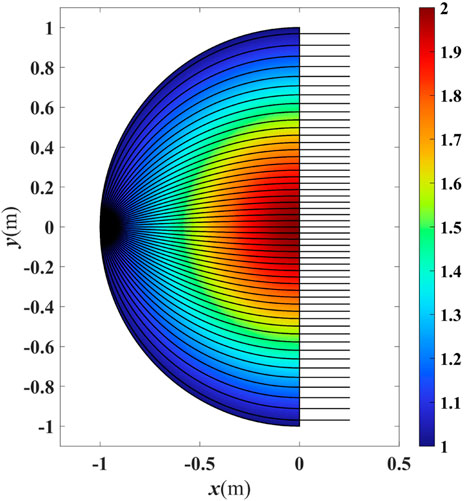
FIGURE 1. Ray trajectories and refractive index of an HMFEL. Parameters n0 = 1 and R = 1 are considered in Eq. 1.
The MFEL and Luneburg lens have been actively studied in the transformation optics (TO) discipline. A connection between the deformation of space and the medium is made possible by TO, based on the form invariance of Maxwell’s equations under a coordinate transformation. This notion gained popularity following the publication of early research on the invisibility cloak by Pendry (2006) and Leonhardt (2006) who asserted that a carefully calculated transformation medium could reproduce the attributes of a deformed space. Having a specific virtual space where wave propagation properties are known, a carefully-selected space deformation could be employed to manipulate the waves’ behavior. It was demonstrated that the hypothetical deformation could be embodied into a material within a physical space using the TO method. TO has been used to create various devices with unique functions, including beam expanders (Rahm et al., 2008; Emiroglu and Kwon, 2010), polarization splitters and transformers (Kwon and Werner, 2008; Mousavi et al., 2017; Eskandari et al., 2018), waveguide couplers (García-Meca et al., 2011; Markov et al., 2012; Eskandari et al., 2017b,a, 2019b; Eskandari and Tyc, 2019), and directivity enhancers (Eskandari et al., 2021a,b; Schmiele et al., 2010; Yao and Jiang, 2011; Gu et al., 2012; Aghanejad et al., 2012; Wu et al., 2013; Giddens and Hao, 2020; Eskandari, 2022; Kadera et al., 2022; Nazarzadeh and Heidari, 2022).
For a virtual space described in Cartesian coordinates (x, y, z), with ϵ and μ as relative permittivity and permeability, the constitutive parameters of the physical space described by the Cartesian coordinates (x′, y′, z′) can be calculated from those of the virtual space by following the formula:
where the Jacobian matrix J = ∂(x′, y′, z′)/∂(x, y, z) characterizes the underlying coordinate transformation between the virtual and physical spaces.
TO serves as a powerful tool for the geometrical reshaping of common GRIN lenses as it preserves the electromagnetic properties of the GRIN lens. In the case of the MFEL, TO has been used to flatten the image and feed planes (Smith et al., 2010; Hunt et al., 2011). Moreover, conformal and quasi-conformal transformations have been employed to transform the circular shape of a two-dimensional (2D) MFEL to a rectangle (Yang et al., 2014; Badri et al., 2020), a square (Tao et al., 2019), and a semi-octagon (Li et al., 2018) for improved integration with photonic devices as a cross-coupler. As a lens reshaping tool, TO can compress the lens in one direction, resulting in a more compact device (Roberts et al., 2009). Numerous studies have employed the Luneburg lens as an example of how to use this concept, either by changing the circular shape into an ellipse (Demetriadou and Hao, 2011b,a; Ebrahimpouri and Quevedo-Teruel, 2019; Liu et al., 2020; Giddens et al., 2021; Chen et al., 2021) or a rectangle (Mateo-Segura et al., 2014; Su and Chen, 2018, 2019; Xu and Chen, 2022). However, reshaping the Luneburg lens has an intrinsic flaw that is not present in the case of MFEL. This topic is expanded upon in the Discussion section. A conformal solution has been proposed to compress a circular MFEL into an elliptical MFEL (EMFEL) (Eskandari et al., 2019a). Slicing the resulting EMFEL in half to achieve directive beams results in significant reflections from the aperture due to the index mismatch.
Here, a 2D HMFEL was compressed using a linear transformation. The conditions that resulted in a reflectionless device were derived and applied. It was shown that the device could provide reasonable scanning as well. The device’s performance was evaluated when the electric field was along the z′ direction (TE polarization) or the magnetic field was along the z′ direction (TM polarization). The design method was validated using COMSOL.
Consider the following linear transformation, which maps a half circle with a radius of one to an ellipse with a semi-major axis of one along the y′-axis and a semi-minor axis of δ (δ < 1) along the x′-axis.
The transformation schematic is shown in Figure 2 for δ = 1/2. The x-constant and y-constant coordinate lines in the virtual space and their mapped counterparts in the physical space are also presented. Because of the 2D nature of the problem, δ, which is the half-ellipse area divided by the half-circle area, quantifies the amount of space occupancy reduction.
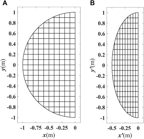
FIGURE 2. Schematic of the underlying transformation between (A) the half circle with radius of one and (B) a half ellipse with semi-minor axis of δ = 0.5 and semi-major axis of one. The x-constant and y-constant lines in virtual space are plotted as well as their mapped version in physical space.
It is known that only the μx′x′, μx′y′ = μy′x′, μy′y′, ɛz′z′ and ɛx′x′, ɛx′y′ = ɛy′x′, ɛy′y′, μz′z′ constitutive parameters contribute to the wave propagation for TE and TM polarization, respectively. It is worth noting that TE (TM) polarization occurs when the electric (magnetic) field is polarized along the z-axis. Using the linear coordinate transformation in Eq. 3, the TO formula in Eq. 2, and the refractive index formula for the HMFEL, the transformation medium of the elliptical HMFEL (EHMFEL) is calculated for the TE and TM polarizations following
where the refractive index of the virtual space has been split into two functions n2(r) = f(r)G(r), in which ɛ(r) = f(r) and μ(r) = G(r). As an additional degree of freedom, the scaling function H(r) is introduced. The permeability (permittivity) has been multiplied (divided) by H(r), which would not change the principal refractive indices (the device functionality). The preceding considerations are made to aid in the suppression of reflections.
The constitutive parameters of an anisotropic medium must meet the following conditions for the interface along the y′-axis between the medium and the vacuum to be omnidirectionally reflectionless (Gok and Grbic, 2016; Eskandari et al., 2019b).
In the instance of EHMFEL, omnidirectionally reflectionless means that the device creates all scanning beams with zero reflections. The above conditions are translated into the following using the transformation medium calculated in Eq. 4
According to the n(r) formula in Eq. 1, the first condition cannot be satisfied for any polarizations at x′ = 0. Hence, it is impossible to have an omnidirectionally reflectionless EHMFEL.
Now we investigate whether the main beam along the optical axis (x′-axis) can be reflectionless. Following a similar approach to that in reference (Eskandari et al., 2017b) and aiming for a derivation of the reflection coefficient at x′ = 0 for a diagonal material, we get the following result for the TM polarization
where θ is the beam’s scan angle, the angle between the beam direction and the x′-axis. Using the duality principle, the reflection coefficient for TE polarization can be easily calculated. Based on Eq. 7, for a diagonal medium to be reflectionless for θ = 0, the impedance terms for TM and TE polarizations should satisfy
In conclusion, the following transformation medium leads to a reflectionless design for θ = 0
where subscript r stands for relative values. Note that the term n(r) should be translated into the physical space coordinates using Eq. 3. For n0 = 1 and R = 1 we have n(r) = 2/(1 + x′2/δ2 + y′2). The principal refractive indices also follow the formula below:
The anisotropy ratio equals
The reflection coefficient at x′ = 0 for the transformation medium described in Eq. 8 follows:
where it assumed that the refractive index along the x′ = 0 boundary is constant and n = 2 (worst case scenario) for the derivation of the maximum possible value. Note that the reflection coefficient is zero for θ = 0; but it is non-zero for other scan angles.
Simulations are carried out for TE and TM polarizations at a frequency of 1.5 GHz. The design parameters are n0 = 1, R = 1, δ = 0.25. The EHMFEL aperture length is 5λ. The standard feeding waveguide WR650 is used with a width of 165 mm. The waveguide is perpendicular to the ellipse’s boundary. To simplify the representation, we will no longer use primed coordinates.
Figure 3 depicts the real part of Ez for the TE1 mode, and Figure 4 illustrates the real part of Hz for the TM0 mode. Both figures, show results for the cases corresponding to the positive scan angles of θ = 0°, 4°, 8°, 12°, 16°, and 20°. The waveguide is moved across the surface to examine the device’s scanning capacity. Because of the symmetry of the structure, only the cases where the waveguide is moved downward are shown.
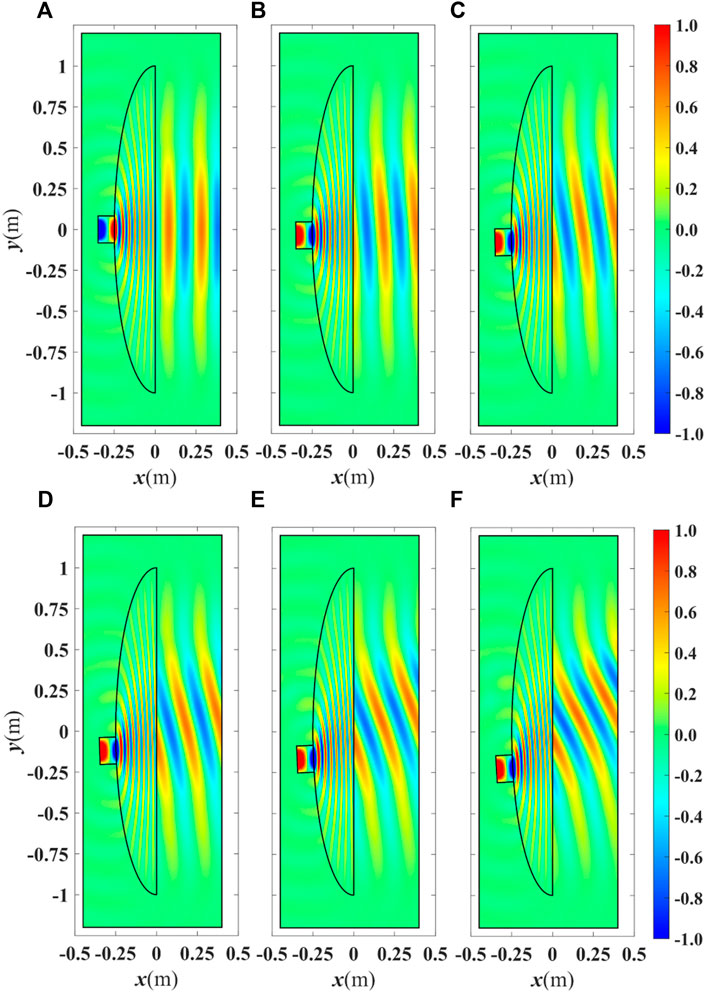
FIGURE 3. Real part of Ez for the EHMFEL excited by a waveguide carrying the TE1 mode at a frequency of 1.5 GHz for a beam direction θ of (A) 0°, (B) +4°, (C) +8°, (D) +12°, (E) +16°, and (F) +20°. The waveguide is moved across the elliptical boundary to achieve beam scanning.
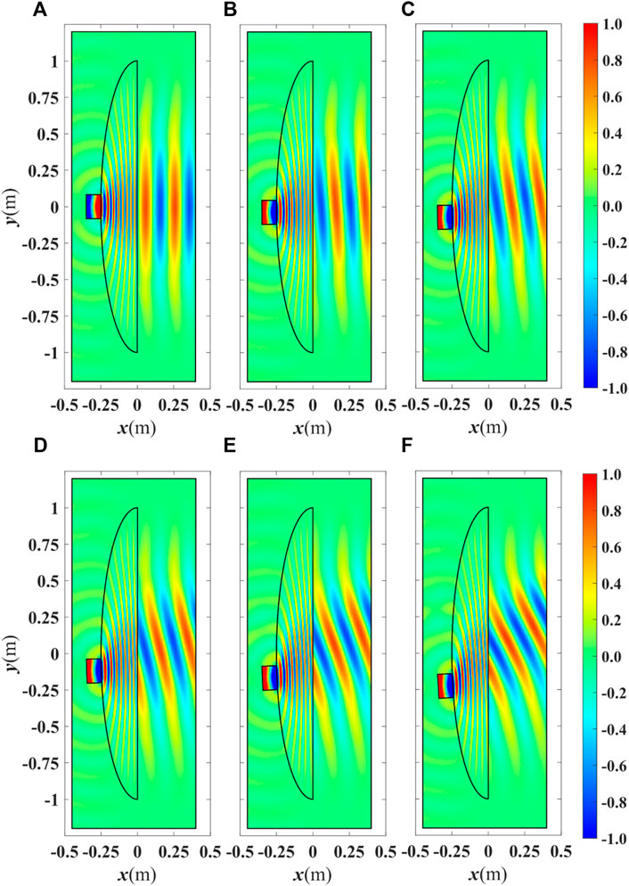
FIGURE 4. Real part of Hz for the EHMFEL excited by a waveguide carrying the TM0 mode at a frequency of 1.5 GHz for a beam direction θ of (A) 0°, (B) +4°, (C) +8°, (D) +12°, (E) +16°, and (F) +20°. The waveguide is moved across the elliptical boundary to achieve beam scanning.
The farfield patterns corresponding to Figures 3, 4 are illustrated in Figure 5. The dotted lines represent the cases where the feed location is mirrored with respect to the x-axis. The results are almost identical for both polarizations, as expected.
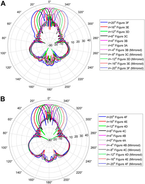
FIGURE 5. Farfield pattern of the EHMFEL in decibels versus θ for (A) the TE1 mode (corresponding to the results depicted in Figure 3) and (B) the TM0 mode (corresponding to the results depicted in Figure 4). The dotted lines represent the cases where the feed location is mirrored with respect to the x-axis.
According to the results in Figures 3–5, it is seen that the EHMFEL performs well for both polarizations. The device achieves a scanning range of −20° ≤ θ ≤ 20°. For a larger scanning angle, an undesirable grating lobe appears. It is practically not expected from HMFEL to provide large scan angles (Fuchs et al., 2007). Furthermore, using Eq. 10, the reflection coefficient Γ is less than 0.024 for −20° ≤ θ ≤ 20°.
Here we studied the lens compression in the case of a Luneburg lens with a radius of one and a refractive index of
The lens works in such a way that φ0 = φ1 + φ2. A beam traveling along the optical axis should have the same total phase as a ray traveling along the rim toward the aperture. If the lens is transformed into any shape, such as an ellipse (as shown in Figure 6), To ensures that
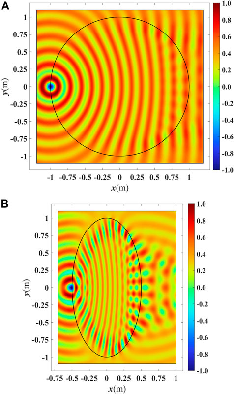
FIGURE 7. Simulation results for (A) an uncompressed Luneburg lens and (B) a compressed Luneburg lens with a semi-minor axis of δ = 0.5. A point source on the lens rim feeds the lenses with a TE polarized wave.
The transformation optics method is employed to reshape the geometry of a HMFEL into an EHMFEL, making the device more compact while preserving its electromagnetic properties. The boundary reflections were studied, and a reflectionless design was proposed for the case where the beam was perpendicular to the EHMFEL aperture. A prototype was designed and simulated for TE and TM polarization using COMSOL. The device provides a scanning range of ±20° with negligible boundary reflections.
The original contributions presented in the study are included in the article; further inquiries can be directed to the corresponding author.
HE conceived the idea, conducted the simulations, and prepared and revised the manuscript.
The author declares that the research was conducted in the absence of any commercial or financial relationships that could be construed as a potential conflict of interest.
All claims expressed in this article are solely those of the authors and do not necessarily represent those of their affiliated organizations, or those of the publisher, the editors, and the reviewers. Any product that may be evaluated in this article, or claim that may be made by its manufacturer, is not guaranteed or endorsed by the publisher.
Aghanejad, I., Abiri, H., and Yahaghi, A. (2012). Design of high-gain lens antenna by gradient-index metamaterials using transformation optics. IEEE Trans. Antennas Propag. 60, 4074–4081. doi:10.1109/tap.2012.2207051
Badri, S. H., Gilarlue, M. M., and Taghipour-Farshi, H. (2020). Rectangular Maxwell’s fisheye lens via transformation optics as a crossing medium for dissimilar waveguides. J. Opt. Soc. Am. B 37, 2437. doi:10.1364/josab.392644
Chen, Q., Giusti, F., Valerio, G., Mesa, F., and Quevedo-Teruel, O. (2021). Anisotropic glide-symmetric substrate-integrated-holey metasurface for a compressed ultrawideband luneburg lens. Appl. Phys. Lett. 118, 084102. doi:10.1063/5.0041586
Demetriadou, A., and Hao, Y. (2011a). A grounded slim luneburg lens antenna based on transformation electromagnetics. IEEE Antennas Wirel. Propag. Lett. 10, 1590–1593. doi:10.1109/lawp.2011.2180884
Demetriadou, A., and Hao, Y. (2011b). Slim luneburg lens for antenna applications. Opt. Express 19, 19925. doi:10.1364/oe.19.019925
Ebrahimpouri, M., and Quevedo-Teruel, O. (2019). Ultrawideband anisotropic glide-symmetric metasurfaces. IEEE Antennas Wirel. Propag. Lett. 18, 1547–1551. doi:10.1109/lawp.2019.2922238
Emiroglu, C. D., and Kwon, D.-H. (2010). Impedance-matched three-dimensional beam expander and compressor designs via transformation optics. J. Appl. Phys. 107, 084502. doi:10.1063/1.3383057
Eskandari, H., Albadalejo-Lijarcio, J. L., Zetterstrom, O., Tyc, T., and Quevedo-Teruel, O. (2021a). H-plane horn antenna with enhanced directivity using conformal transformation optics. Sci. Rep. 11, 14322. doi:10.1038/s41598-021-93812-6
Eskandari, H., Attari, A. R., and Majedi, M. S. (2018). Design of polarization splitting devices with ideal transmission and anisotropy considerations. J. Opt. Soc. Am. B 35, 1585–1595. doi:10.1364/josab.35.001585
Eskandari, H., Attari, A. R., and Majedi, M. S. (2017a). Reflectionless design of a nonmagnetic homogeneous optical waveguide coupler based on transformation optics. J. Opt. Soc. Am. B 35, 54–60. doi:10.1364/josab.35.000054
Eskandari, H., Majedi, M. S., Attari, A. R., and Quevedo-Teruel, O. (2019a). Elliptical generalized Maxwell fish-eye lens using conformal mapping. New J. Phys. 21, 063010. doi:10.1088/1367-2630/ab2471
Eskandari, H., Majedi, M. S., and Attari, A. R. (2017b). Reflectionless compact nonmagnetic optical waveguide coupler design based on transformation optics. Appl. Opt. 56, 5599–5606. doi:10.1364/ao.56.005599
Eskandari, H., Quevedo-Teruel, O., Attari, A. R., and Majedi, M. S. (2019b). Transformation optics for perfect two-dimensional non-magnetic all-mode waveguide couplers. Opt. Mat. Express 9, 1320–1332. doi:10.1364/ome.9.001320
Eskandari, H., Saviz, S., and Tyc, T. (2021b). Directivity enhancement of a cylindrical wire antenna by a graded index dielectric shell designed using strictly conformal transformation optics. Sci. Rep. 11, 1–11. doi:10.1038/s41598-021-92200-4
Eskandari, H. (2022). Strictly conformal transformation optics for directivity enhancement and unidirectional cloaking of a cylindrical wire antenna. Sci. Rep. 12, 16278. doi:10.1038/s41598-022-20503-1
Eskandari, H., and Tyc, T. (2019). Controlling refractive index of transformation-optics devices via optical path rescaling. Sci. Rep. 9, 18412–12. doi:10.1038/s41598-019-54516-0
Fuchs, B., Lafond, O., Rondineau, S., Himdi, M., and Coq, L. L. (2007). Off-axis performances of half Maxwell fish-eye lens antennas at 77 GHz. IEEE Trans. Antennas Propag. 55, 479–482. doi:10.1109/tap.2006.886576
Fuchs, B., Lafond, O., Rondineau, S., and Himdi, M. (2006). Design and characterization of half Maxwell fish-eye lens antennas in millimeter waves. IEEE Trans. Microw. Theory Tech. 54, 2292–2300. doi:10.1109/tmtt.2006.875255
García-Meca, C., Tung, M. M., Galán, J. V., Ortuño, R., Rodríguez-Fortuño, F. J., Martí, J., et al. (2011). Squeezing and expanding light without reflections via transformation optics. Opt. Express 19, 3562–3575. doi:10.1364/oe.19.003562
Giddens, H., Andy, A. S., and Hao, Y. (2021). Multimaterial 3-d printed compressed luneburg lens for mm-wave beam steering. IEEE Antennas Wirel. Propag. Lett. 20, 2166–2170. doi:10.1109/lawp.2021.3109591
Giddens, H., and Hao, Y. (2020). Multibeam graded dielectric lens antenna from multimaterial 3-d printing. IEEE Trans. Antennas Propag. 68, 6832–6837. doi:10.1109/tap.2020.2978949
Gok, G., and Grbic, A. (2016). A physical explanation for the all-angle reflectionless property of transformation optics designs. J. Opt. 18, 044020. doi:10.1088/2040-8978/18/4/044020
Gu, C., Yao, K., Lu, W., Lai, Y., Chen, H., Hou, B., et al. (2012). Experimental realization of a broadband conformal mapping lens for directional emission. Appl. Phys. Lett. 100, 261907. doi:10.1063/1.4731877
Huang, M., Yang, S., Gao, F., Quarfoth, R., and Sievenpiper, D. (2014). A 2-d multibeam half Maxwell fish-eye lens antenna using high impedance surfaces. IEEE Antennas Wirel. Propag. Lett. 13, 365–368. doi:10.1109/lawp.2014.2306207
Hunt, J., Jang, G., and Smith, D. R. (2011). Perfect relay lens at microwave frequencies based on flattening a Maxwell lens. J. Opt. Soc. Am. B 28, 2025–2029. doi:10.1364/josab.28.002025
Kadera, P., Sanchez-Pastor, J., Eskandari, H., Tyc, T., Sakaki, M., Schusler, M., et al. (2022). Wide-angle ceramic retroreflective luneburg lens based on quasi-conformal transformation optics for mm-wave indoor localization. IEEE Access 10, 41097–41111. doi:10.1109/access.2022.3166509
Kwon, D.-H., and Werner, D. H. (2008). Polarization splitter and polarization rotator designs based on transformation optics. Opt. Express 16, 18731–18738. doi:10.1364/oe.16.018731
Leonhardt, U. (2006). Optical conformal mapping. Science 312, 1777–1780. doi:10.1126/science.1126493
Li, S., Zhou, Y., Dong, J., Zhang, X., Cassan, E., Hou, J., et al. (2018). Universal multimode waveguide crossing based on transformation optics. Optica 5, 1549–1556. doi:10.1364/optica.5.001549
Liu, K., Yang, S., Chen, C., Qu, S.-W., and Chen, Y. (2020). A wide-scanning ellipsoid lens antenna fed by phased array antenna. Int. J. RF Microw. Comput. Aided. Eng. 30. doi:10.1002/mmce.22127
Markov, P., Valentine, J. G., and Weiss, S. M. (2012). Fiber-to-chip coupler designed using an optical transformation. Opt. Express 20, 14705–14713. doi:10.1364/oe.20.014705
Mateo-Segura, C., Dyke, A., Dyke, H., Haq, S., and Hao, Y. (2014). Flat luneburg lens via transformation optics for directive antenna applications. IEEE Trans. Antennas Propag. 62, 1945–1953. doi:10.1109/tap.2014.2302004
Mousavi, S. S. S., Majedi, M. S., and Eskandari, H. (2017). Design and simulation of polarization transformers using transformation electromagnetics. Optik 130, 1099–1106. doi:10.1016/j.ijleo.2016.11.129
Nazarzadeh, F., and Heidari, A. A. (2022). Wideband flat reflector antenna based on conformal transformation optics. Optik 264, 169429. doi:10.1016/j.ijleo.2022.169429
Pendry, J. B., Schurig, D., and Smith, D. R. (2006). Controlling electromagnetic fields. Science 312, 1780–1782. doi:10.1126/science.1125907
Rahm, M., Roberts, D. A., Pendry, J. B., and Smith, D. R. (2008). Transformation-optical design of adaptive beam bends and beam expanders. Opt. Express 16, 11555–11567. doi:10.1364/oe.16.011555
Roberts, D. A., Kundtz, N., and Smith, D. R. (2009). Optical lens compression via transformation optics. Opt. Express 17, 16535–16542. doi:10.1364/oe.17.016535
Schmiele, M., Varma, V. S., Rockstuhl, C., and Lederer, F. (2010). Designing optical elements from isotropic materials by using transformation optics. Phys. Rev. A . Coll. Park. 81, 033837. doi:10.1103/physreva.81.033837
Shi, Y., Li, K., Wang, J., Li, L., and Liang, C.-H. (2015). An etched planar metasurface half Maxwell fish-eye lens antenna. IEEE Trans. Antennas Propag. 63, 3742–3747. doi:10.1109/tap.2015.2438337
Smith, D. R., Urzhumov, Y., Kundtz, N. B., and Landy, N. I. (2010). Enhancing imaging systems using transformation optics. Opt. Express 18, 21238–21251. doi:10.1364/oe.18.021238
Su, Y., and Chen, Z. N. (2018). A flat dual-polarized transformation-optics beamscanning luneburg lens antenna using PCB-stacked gradient index metamaterials. IEEE Trans. Antennas Propag. 66, 5088–5097. doi:10.1109/tap.2018.2858209
Su, Y., and Chen, Z. N. (2019). A radial transformation-optics mapping for flat ultra-wide-angle dual-polarized stacked GRIN MTM luneburg lens antenna. IEEE Trans. Antennas Propag. 67, 2961–2970. doi:10.1109/tap.2019.2900346
Tao, S., Zhou, Y., and Chen, H. (2019). Maxwell’s fish-eye lenses under schwartz-christoffel mappings. Phys. Rev. A . Coll. Park. 99, 013837. doi:10.1103/physreva.99.013837
Tyc, T., Herzánová, L., Šarbort, M., and Bering, K. (2011). Absolute instruments and perfect imaging in geometrical optics. New J. Phys. 13, 115004. doi:10.1088/1367-2630/13/11/115004
Wu, Q., Jiang, Z. H., Quevedo-Teruel, O., Turpin, J. P., Tang, W., Hao, Y., et al. (2013). Transformation optics inspired multibeam lens antennas for broadband directive radiation. IEEE Trans. Antennas Propag. 61, 5910–5922. doi:10.1109/tap.2013.2282905
Xu, H.-X., Wang, G.-M., Tao, Z., and Cai, T. (2014). An octave-bandwidth half Maxwell fish-eye lens antenna using three-dimensional gradient-index fractal metamaterials. IEEE Trans. Antennas Propag. 62, 4823–4828. doi:10.1109/tap.2014.2330615
Xu, R., and Chen, Z. N. (2022). A transformation-optics-based flat metamaterial luneburg lens antenna with zero focal length. IEEE Trans. Antennas Propag. 70, 3287–3296. doi:10.1109/tap.2021.3137528
Yang, F., Mei, Z. L., and Cui, T. J. (2014). Design and experiment of perfect relay lens based on the schwarz-christoffel mapping. Appl. Phys. Lett. 104, 073510. doi:10.1063/1.4866284
Keywords: half Maxwell fish-eye lens, linear transformation, lens compression, transformation optics, optical axis
Citation: Eskandari H (2022) A reflectionless compact elliptical half Maxwell fish-eye lens designed by transformation optics. Front. Mater. 9:1079809. doi: 10.3389/fmats.2022.1079809
Received: 25 October 2022; Accepted: 14 November 2022;
Published: 08 December 2022.
Edited by:
Yichao Liu, Taiyuan University of Technology, ChinaCopyright © 2022 Eskandari. This is an open-access article distributed under the terms of the Creative Commons Attribution License (CC BY). The use, distribution or reproduction in other forums is permitted, provided the original author(s) and the copyright owner(s) are credited and that the original publication in this journal is cited, in accordance with accepted academic practice. No use, distribution or reproduction is permitted which does not comply with these terms.
*Correspondence: Hossein Eskandari, SG9zc2Vpbi5za2FuZGFyaUBnbWFpbC5jb20=
Disclaimer: All claims expressed in this article are solely those of the authors and do not necessarily represent those of their affiliated organizations, or those of the publisher, the editors and the reviewers. Any product that may be evaluated in this article or claim that may be made by its manufacturer is not guaranteed or endorsed by the publisher.
Research integrity at Frontiers

Learn more about the work of our research integrity team to safeguard the quality of each article we publish.