 Shichao Liu
 Yuanming Li
 Changbing Tang
- Nuclear Power Institute of China, Science and Technology on Reactor System Design Technology Laboratory, Chengdu, China
The thermal-mechanical performance of tri-isotropic (TRISO) particles with residual pores used in light water reactors (LWRs) was investigated. The effect of residual pore structure on the stress distribution of the inner dense pyrolytic carbon (IPyC) layer, SiC layer, and outer dense pyrolytic carbon (OPyC) layer was studied. The dimensional changes and fission gas release of the fuel particle layers were calculated. Residual pores on the SiC layer can affect the stress distribution of the coated layers. The residual pores, especially the tetrahedrons, may be the source of cracks in the SiC layer, which can break or cause the loss of the capacity of the SiC layer. Residual pores have little influence on the stress distribution of the IPyC and OPyC layers.
Introduction
Tristructural isotropic (TRISO) particles have been chosen as reactor fuel in various kinds of reactors, including thorium high-temperature reactors (THTR-300s) and high-temperature gas-cooled reactors (HTGRs) (Powers and Wirth, 2010; Besmann et al., 2014). A 10 MWth prototype pebble bed high-temperature reactor (HTR-10) built in China applied TRISO particles with UO2 kernels as a fuel element. At the same time, TRISO particles were fabricated as fully ceramic microencapsulated fuel (FCM™), and their application in light water reactors (LWRs) has been investigated. FCM™ fuel was deemed to improve the safety of LWRs by increasing the capacity of fission products and decreasing the release of fission gas. TRISO particles were applied in LWRs using uranium nitride (UN) as a kernel in order to increase the fissile loading (Ross and Matthews, 1988; Terrani et al., 2012; Xin et al., 2019). The performance of TRISO particles used in LWRs has been studied, and the result indicated that the failure of the SiC layer coating in TRISO particles was about 4 × 10⁻⁵.
A TRISO particle is a spherically multicoated composite with a diameter of approximately about 1 mm. A TRISO particle consists of a fuel kernel (typically an oxide, carbide or oxicarbide), a porous graphite buffer layer (buffer), a dense inner pyrolytic carbon layer (IPyC), a silicon carbide layer (SiC), and a dense outer pyrolytic carbon layer (OPyC). The coated layers play different roles. A buffer layer accommodates kernel deformation and provides space for fission gas (Miller et al., 2003; Besmann et al., 2012; Hales et al., 2013; Besmann et al., 2014). The IPyC layer protects the SiC from chemical attack and offers a deposition surface for the SiC layer. The SiC layer is the most important mechanical structure, as it behaves as a miniature pressure vessel and contains the fission product. The OPyC layer reduces tensile stress in the SiC layer (Li et al., 2018). The SiC layer bears the inner pressure produced by fission gas and the reaction between the kernel and the buffer layers and resists the diffusion of the fission product. The failure probability may be an important criterion for the safety evaluation of TRISO particles (Sen et al., 2013; Chen et al., 2019).
The in-pile performance of TRISO particles has been studied in recent decades under both normal operations and accident conditions. Many software programs have been exploited to simulate the behavior of TRISO particles used in HTGRs, such as PARFUME, PASTA, ATLAS, STRESS3, and TIMCOAT. The recommended material properties have been summarized in the software mentioned above (Powers and Wirth, 2010). The fission gas release, deformation of coated layers, stress distribution, and failure mechanisms have been investigated. Two kinds of models were established, including a 1D and a 3D model. The PARFUME code, pioneered by Miller at the Idaho National Laboratory (INL), is a 1D model that can calculate the internal pressure, heat transfer, and stress distribution. Similar codes, such as TIMCOAT and PASTA, are also 1D models, and the gap between the IPyC and buffer layers can be calculated. A three-dimensional finite element method (such as ABAQUS and COMSOL software) is used to analyze the performance of TRISO particles, including the steady state and accident conditions (Miller et al., 2003; Collin, 2014; Liu et al., 2014). The effect of fabrication defects on the performance was studied, including the aspherical coated layer and the localized thinning of the SiC layer. The result indicates that fabrication defects increase the tangential stress of the coated layers, and the failure probability increases at the same time. Residual pores formed during the chemical vapor deposition (CVD) process (Snead et al., 2014; Liu et al., 2015). Residual pores have different structures, including spherical pores, ellipsoidal pores, and irregular pores. The effect of residual pores on the in-pile performance of TRISO particles was not discussed.
The current study estimates the effect of residual pores with different structures on the performance of TRISO particles. The fission gas release and deformation of the coated layer were investigated. The stress distribution of the coated layer was simulated by considering the irradiation deformation in pyrolytic carbon and SiC layers.
Material and behavior models
Material properties
The material properties used to simulate the performance of TRISO particles have been summarized in literature (Powers and Wirth, 2010; Collin, 2014), including the fuel kernel, PyC layer, buffer layer, and SiC layer. The main properties of the UO2 kernel considered in this paper are thermal conductivity and irradiation swelling, which can affect the deformation and temperature distribution. The thermal conductivity of the UO2 kernel after irradiation was modified based on its connectivity before irradiation. The thermal conductivity before irradiation can be written as follows:
where T is the temperature (K).
The thermal conductivity of the irradiated UO2 kernel can be modified as follows:
where k0 (W/m/K) is the thermal conductivity of the UO2 kernel before irradiation, expressed as Formula 1.
FD is the factor of solved fission product, expressed as Formula 3; FP is the factor of sedimentary fission product, expressed as Formula 4; FM is the influence factor of porosity and can be expressed as Formula 5; FR is the influence factor of irradiation and can be expressed as Formula 6.
where Bu is burnup (%FIMA), T is the temperature (K), P is the porosity (%), and s is the shape factor with a value of 0.5.
The irradiation swelling of the UO2 kernel consists of solid and gas fission products. The solid and gas product swelling can be written as:
where
Young’s modulus of the pyrolytic carbon layer in TRISO particle can be expressed as follows:
where Ф is the neutron flux (×1025 n/m2), ρpyc is the density of the PyC layer (kg/m3), and T is the temperature (K).
The irradiation deformation of PyC along radial and tangential directions was written as follows:
where Ф is the neutron flux (×1025 n/m2) and
The irradiation creep rate of PyC layers along the radial direction can be written as follows, and the creep rate along other directions can be expressed by Formula 12.
where Ф is the neutron flux (×1025 n/m2), and vc is the Poisson ratio (the value is 0.5 for both dense and buffer creep rates). K is the creep constant (m2∙n−1∙MPa−1∙s−1), which can be expressed as follows:
where T is the temperature (°C), and ρ0 is the initial density (g/cm3).
The SiC layer is the main protective screen for resisting the fission gas release. The elastic modulus, thermal conductivity, and thermal expansion can be written as follows:
where P is the porosity with a value of 0.05, and T is the temperature. The Poisson ratio is 0.13.
Fission gas release and failure probability of SiC layer
The UO2 kernel reacted with the buffer layer, and CO was produced. The production amount of CO was calculated by the Proksch model used in the literature (Besmann et al., 2014).
where O/F is the release amount of CO, and T is the temperature (K).
Recoil release and diffusion release were considered the main release mechanisms for fission gas release, including Xe, Kr, and He. Recoil release will be the predominant mechanism at low temperatures, and the release portion of fission gas can be calculated from the following empirical equation (Besmann et al., 2014):
where f is the fission gas release portion, S is the superficial area of fuel particle (m2), V is the volume of fuel particle (m3), and a is the mean recoil range of fission gas atoms (m), and the mean recoil ranges of Xe and Kr are 3.98 μm and 5.68μm, respectively.
The main mechanism of fission gas release at high temperatures is diffusion release. The Booth classical diffusion model was employed in this study to compute the final release of fission gas from loose pyrolytic carbon through the gap by the diffusion mechanism. The effective diffusion coefficient of fission gas atoms within the fuel grains can be set from the following empirical relation (Miller and Petti, 2009; Zhang et al., 2020):
where Dg is the effective diffusion coefficient of fission gas atoms within the fuel grains.
Demonstration problems
Geometry and boundary conditions
The performance of the TRISO particles was simulated by establishing a 1/8 characteristic sphere unit. The fission gas release, internal pressure, and stress distribution on the coated layers were calculated. Figure 1 shows the calculation model and boundary condition. Fast neutron fluence and burnup were set to increase linearly with irradiation time, and the values reached 18×1025 n/m2 and 19% FIMA (fissions per initial metal atom), respectively, at the end of life. The temperature on the outer particle surface was set at 1200 K, which was similar to the literature. The structure size of the TRISO particle was set as follows: the diameter of the UO2 kernel was 800 μm, and the thicknesses of the buffer, IPyC, SiC, and OPyC layers were 100 μm, 30 μm, 40 μm, and 30 μm, respectively.

FIGURE 1. Schematic diagram of a characteristic TRISO particle.
Typical residual pores
A TRISO particle was fabricated, and the microstructure was examined by SEM. The microstructure of the TRISO particle is shown in Figure 2. Different kinds of residual pores were found in the SiC layers, including spheres, ovoids, and tetrahedrons. The average diameter of the residual pore was about 2 μm, but the largest one reached 4–5 μm. A residual pore may be the source of cracks in the layer. Stress concentration occurred during operation time. In order to show the influence of residual pores, the size of the residual pore was amplified, and the size of the residual pore with different shapes was set to 5 μm in the calculated model. To investigate the influence of residual pores on the performance of TRISO particles, residual pores with different shapes were created in the middle part of the SiC layer in the model.
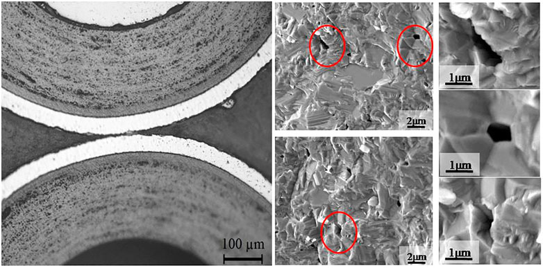
FIGURE 2. Microstructure of typical pores in the SiC layer.
Results and discussion
Gap size and fission gas release
The deformation of the coated layers will cause a dimensional change in the TRISO particle. A gap between the IPyC and the buffer layer appeared during the irradiation process, which had been found in TRISO particles examined post-irradiation and reported in the literature (Miller et al., 2003; Besmann et al., 2014). The gap size may increase the kernel temperature because of the low thermal conductivity of the gap. The variation of gap and coated layers size is shown in Figure 3. The buffer layer shrinks rapidly at first due to the irradiation densification, which is in agreement with the literature (Miller et al., 2003; Besmann et al., 2014). At the same time, the IPyC layer shrinks due to the irradiation deformation, as shown in Eqs 10 and 11. The IPyC layer is pinned with the SiC layer, and no debonding occurs between the two layers (Besmann et al., 2014). In contrast, the IPyC layer and buffer layer debonded because of the deformation of the two layers, and a gap was created. The gap size increased rapidly at first because of the deformation of the buffer layer. The maximum gap size was reached when the neutron flux reached 2×1025 n/m2, and the maximum value was about 23 μm. Then the gap size decreased with the increasing neutron flux due to the swelling of the kernel and the deformation of the IPyC layer. This phenomenon has been proved in previous work (Liu et al., 2019).
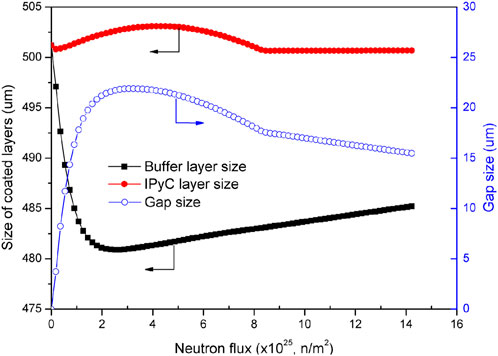
FIGURE 3. Dimensional variation of the kernel and coated layers.
Figure 4 is the fission gas release of the TRISO particle. The fission gasses of Xe, Kr, and He were calculated based on the recoil and diffusion mechanism as shown in Eqs 19, 20. The internal pressure was calculated by the van der Waals equation. The amount of fission gas increased approximately linearly as the fast neutron fluence increased. The largest amount of fission gas was Xe. The diffusion distance of fission gas (grain size) was set as 20 μm according to the literature (Liu et al., 2019), and the release amount was in agreement with the literature. The release amounts of Xe, Kr, and He were 2.34 × 10⁻⁸ mol, 3.53 × 10⁻⁹ mol, and 2.27 × 10⁻⁹ mol, respectively. The total fission gas release amount was about 2.92 × 10⁻⁸ mol. Fission gas release can increase the internal pressure of the TRISO particle, which may cause the pressure vessel failure of the TRISO particle.
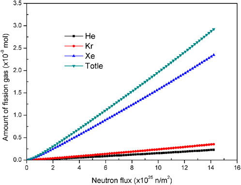
FIGURE 4. Variation of the amount of gas released from a TRISO particle with neutron flux.
Effect of residual pore on the performance of coated layers
Three residual pores with different structures, including spheres, ovoids, and tetrahedrons, were found during the fabrication process, as shown in Figure 2. The effect of residual pores with the different structures on the performance of TRISO particles was simulated by establishing characteristic units with residual pores. Figure 5 shows contour plots of the tangential stress for the TRISO particles with different residual pore structures at the beginning and end of operation time. Obvious stress concentration occurred around the residual pore due to the deformation of the coated layers during the operation process. The tetrahedron pore suffered maximum stress due to the stress concentration at the cusp part. The maximum stress was much higher at the end of operation time than at the beginning.
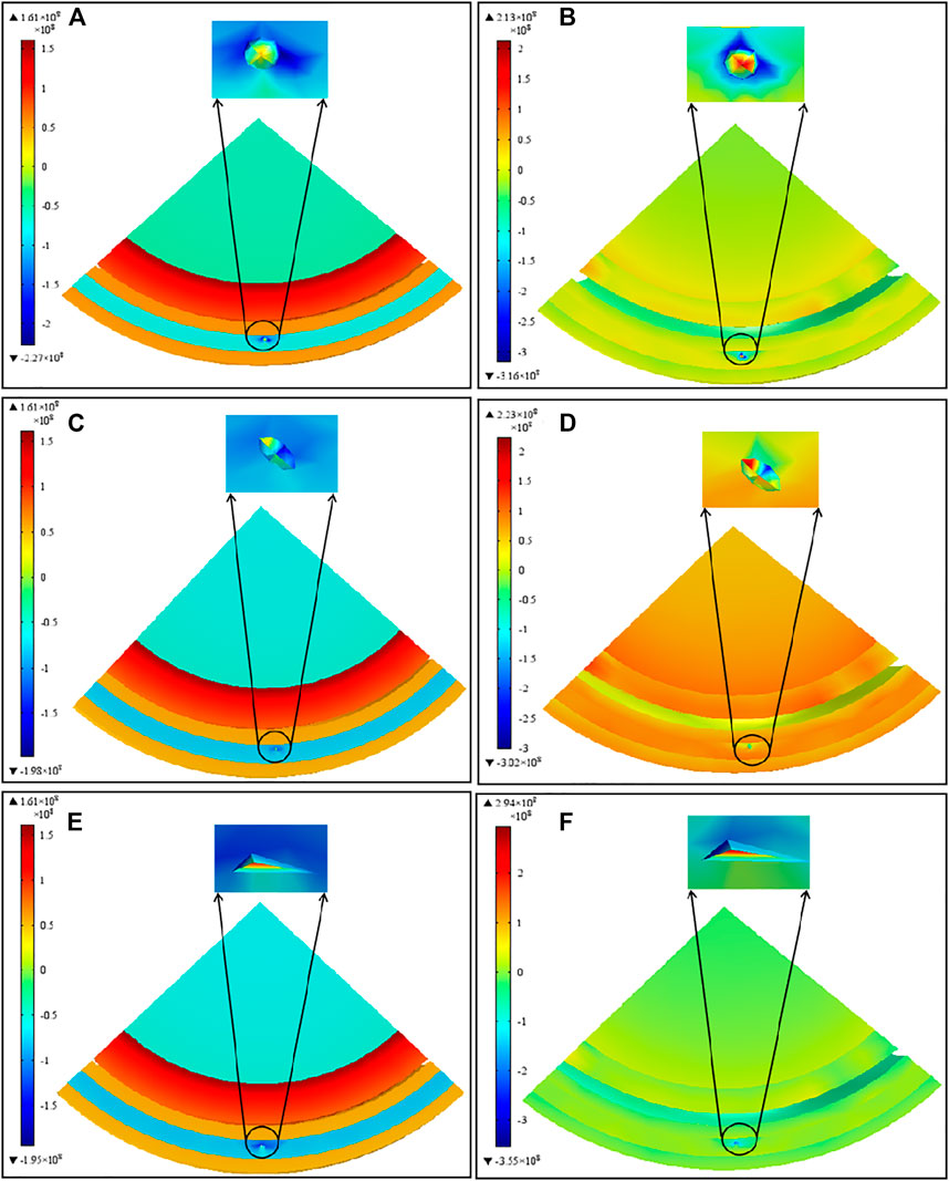
FIGURE 5. Contour plots of the tangential stress for a TRISO particle with different residual pore sizes. (A,B) are the spherical pores at the beginning and end of the operation time, (C,D) are ovoid pores at the beginning and end of the operation time, (E,F) are the tetrahedral pores at the beginning and end of operation time.
Tangential stress curves of the SiC layer in TRISO particles with different residual pore structures are shown in Figure 6. Hoop stress has a similar variation trend for the SiC layer with and without residual pores. Irradiation shrinkage occurred on the Pyc layer, and that shrinkage applied compressive force on the SiC layer at the beginning. The irradiation shrinkage and the compressive force saturated at high neutron flux first, which decreased the hoop stress of the SiC layer. SiC layer deformation occurred due to the swelling and thermal expansion, and the hoop stress of the SiC layer increased. The hoop stress increased with neutron flux, and the maximum hoop stress reached about 8.0×1025 n/m2, then the hoop stress decreased with the increasing of neutron flux. The hoop stress was stable when the neutron flux was greater than 8.0×1025 n/m2. This phenomenon was caused by the deformation of the Pyc layers. The deformation and hoop stress of the coated layers is steady at irradiation anaphase. Residual pores increased the hoop stress of the SiC layer significantly. The SiC layer with a tetrahedron pore possessed the highest hoop stress due to the stress concentration at the cutting edge of the tetrahedron pore. The maximum hoop stress of the SiC layer with a tetrahedron pore was up to 500 MPa, which may break the SiC layer.
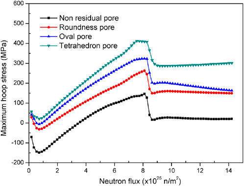
FIGURE 6. Maximum hoop stress of the SiC layer with and without residual pores.
The hoop stress curves of IPyC and OPyC layers are shown in Figure 7. All kinds of residual pores can dramatically increase the hoop stress of IPyC and OPyC layers; however, the influence of residual pore structure was limited. The maximum hoop stress of the IPyC layers with and without a residual pore was 450 MPa and 300 MPa, respectively, which was larger than the strength of the IPyC layer. Larger hoop stress may cause a broken IPyC layer. The maximum hoop stress of the OPyC layer increased from 130 MPa to 200 MPa when the residual pore appeared. The influence of the residual pore structure on the stress condition of IPyC and OPyC layers was minor.
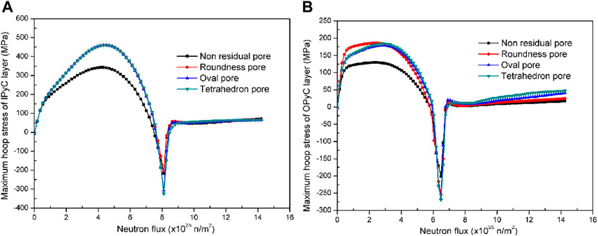
FIGURE 7. Hoop stress curves of the IPyC and OPyC layers with neutron flux.
Conclusion
The effect of residual pore structure on the performance of TRISO was simulated using COMSOL software. A gap between the IPyC and the buffer layer appeared, and the gap size increased with neutron flux; the maximum size reached 23 μm when the neutron flux reached 18×1025 n/m2. The residual pore can change the stress distribution of the coated layers. Residual pores can dramatically increase the SiC layer’s hoop stress, especially tetrahedral pores. The stress concentration at the cutting edge of the tetrahedron pore greatly increased maximum hoop stress. The maximum value reached 500 MPa, which was much higher than the SiC strength. Thus, tetrahedral pores should be avoided during the fabrication process to maintain the integrity of the SiC layer. The hoop stress has little influence on the IPyC and OPyC layers.
Data availability statement
The original contributions presented in the study are included in the article/Supplementary material; further inquiries can be directed to the corresponding author.
Author contributions
SL: validation, formal analysis, writing—original draft. YL: conceptualization, supervision. PC: writing—review and editing. YZ: conceptualization, supervision. CT: formal analysis, writing—original draft.
Conflict of interest
The authors declare that the research was conducted in the absence of any commercial or financial relationships that could be construed as a potential conflict of interest.
Publisher’s note
All claims expressed in this article are solely those of the authors and do not necessarily represent those of their affiliated organizations or those of the publisher, the editors, and the reviewers. Any product that may be evaluated in this article, or claim that may be made by its manufacturer, is not guaranteed or endorsed by the publisher.
References
Besmann, T. M., Ferber, M. K., Lin, H., and Collin, B. P. (2014). Fission product release and survivability of UN-kernel LWR TRISO fuel. J. Nucl. Mater. 448, 412–419. doi:10.1016/j.jnucmat.2013.10.034
Besmann, T. M., Shin, D., and Lindemer, T. B. (2012). Uranium nitride as LWR TRISO fuel: Thermodynamic modeling of U-C-N. J. Nucl. Mater. 427, 162–168. doi:10.1016/j.jnucmat.2012.04.021
Chen, P., Qiu, S., Liu, S., Zhou, Y., Xin, Y., Gao, S., et al. (2019). Preliminary analysis of a fully ceramic microencapsulated fuel thermal–mechanical performance. Mathematics 7, 448–460. doi:10.3390/math7050448
Collin, B. P. (2014). Modeling and analysis of UN TRISO fuel for LWR application using the PARFUME code. J. Nucl. Mater. 451, 65–77. doi:10.1016/j.jnucmat.2014.03.032
Hales, J. D., Williamson, R. L., Novascone, S., Perez, D., Spencer, B., and Pastore, G. (2013). Multidimensional multiphysics simulation of TRISO particle fuel. J. Nucl. Mater. 443, 531–543. doi:10.1016/j.jnucmat.2013.07.070
Hunt, R. D., Silva, C. M., Lindemer, T. B., Johnson, J., and Collins, J. (2014). Preparation of UC0.07-0.10N0.90-0.93 spheres for TRISO coated fuel particles. J. Nucl. Mater. 448, 399–403. doi:10.1016/j.jnucmat.2013.04.007
Li, W., Wu, X., Liu, S., Lu, W., Yifei, M., Changbing, T., et al. (2018). Performance analysis of TRISO coated fuel particle with UN kernel. Atomic Energy Sci. Technol. 52 (2), 283–289. doi:10.7538/yzk.2017.youxian.0217
Liu, M., Liu, B., Shao, Y., and Wang, J. (2014). Optimization design of the coating furnace by 3-d simulation ofspouted bed dynamics in the coater. Nucl. Eng. Des. 271, 68–72. doi:10.1016/j.nucengdes.2013.11.012
Liu, R., Liu, M., Chang, J., Shao, Y., and Liu, B. (2015). An improved design of TRISO particle with porous SiC inner layer byfluidized bed-chemical vapor deposition. J. Nucl. Mater. 467, 917–926. doi:10.1016/j.jnucmat.2015.10.055
Liu, S., Chen, P., Zhou, Y., Hua, P., Yong, X., Xi, Q., et al. (2019). “Effect of residual pore on the performance of UN kernel TRISO particle fuel,” in Proceedings of the International Nuclear Fuel Cycle Conference, Seattle, WA, USA, September 2019 (Global), 22–27.
Miller, G. K., Petti, D. A., Varacalle, D. J., and Maki, J. T. (2003). Statistical approach and benchmarking for modeling of multi-dimensional behavior in TRISO-coated fuel particles. J. Nucl. Mater. 317, 69–82. doi:10.1016/s0022-3115(02)01702-6
Miller, G. K., and Petti, D. A. (2009). “PARFUM theory and model basis report,”. INL/EXT-08-14497 (USA, ID, Idaho falls: Idaho National Lab.). doi:10.2172/1471713
Powers, J. J., and Wirth, B. D. (2010). A review of TRISO fuel performance models. J. Nucl. Mater. 405, 74–82. doi:10.1016/j.jnucmat.2010.07.030
Ross, S. R., and Matthews, R. B. (1988). Thermal conductivity correlation for uranium nitride fuel between 10 and 1923 K. J. Nucl. Mater. 151, 318–326. doi:10.1016/0022-3115(88)90026-8
Sen, R. S., Pope, M. A., Ougouag, A. M., and Pasamehmetoglu, K. O. (2013). Assessment of possible cycle lengths for fully encapsulated microstructure fueled light water reactor concepts. Nucl. Eng. Des. 255, 310–320. doi:10.1016/j.nucengdes.2012.11.007
Snead, L. L., Terrani, K. A., Katoh, Y., Silva, C., Leonard, K., and Perez-Bergquist, A. (2014). Stability of SiC-matrix microencapsulated fuel constituents at relevant LWR conditions. J. Nucl. Mater. 448, 389–398. doi:10.1016/j.jnucmat.2013.09.056
Terrani, K. A., Snead, L. L., and Cehin, J. C. (2012). Fully ceramic microencapsulated fuels for LWRs. Trans. Am. Nucl. Soc. 106, 1 106–107.
Xin, Y., Li, Y., Tang, C., Liu, S., Chen, P., Zhou, Y., et al. (2019). Dimension optimization design of TRISO fuel particle in metal matrix microencapsulated fuels. Nucl. Power Eng. 40 (2), 173–176.
Keywords: TRISO particle, residual pore structure, stress distribution, thermal-mechanical performance, coated layer deformation
Citation: Liu S, Li Y, Chen P, Zhou Y and Tang C (2023) Effect of residual pore structure on the performance of TRISO particle fuel. Front. Mater. 9:1072255. doi: 10.3389/fmats.2022.1072255
Received: 17 October 2022; Accepted: 29 November 2022;
Published: 04 January 2023.
Edited by:
Qun Li, Xi’an Jiaotong University, ChinaReviewed by:
Yanan He, Xi’an Jiaotong University, ChinaYujin Wang, Harbin Institute of Technology, China
Hongjun Yu, Harbin Institute of Technology, China
Copyright © 2023 Liu, Li, Chen, Zhou and Tang. This is an open-access article distributed under the terms of the Creative Commons Attribution License (CC BY). The use, distribution or reproduction in other forums is permitted, provided the original author(s) and the copyright owner(s) are credited and that the original publication in this journal is cited, in accordance with accepted academic practice. No use, distribution or reproduction is permitted which does not comply with these terms.
*Correspondence: Shichao Liu, aGl0X2xzY0AxNjMuY29t