- 1Department of Construction Management, Qujing Normal University, Qujing, Yunnan, China
- 2Department of Civil Engineering, Coimbatore Institute of Technology, Coimbatore, Tamil Nadu, India
- 3Department of Civil Engineering, College of Engineering, University of Duhok, Duhok, Iraq
- 4Department of Civil Engineering, College of Engineering, Nawroz University, Duhok, Iraq
- 5Department of Civil Engineering, College of Engineering, Najran University, Najran, Saudi Arabia
- 6Department of Civil Engineering, Universitas Abulyatama, Aceh Besar, Indonesia
- 7Department of Civil Engineering, Zakir Husain Engineering College, Aligarh Muslim University, Aligarh, India
- 8Peter the Great St. Petersburg Polytechnic University, Petersburg, Russia
This article examines the performance of Carbon Fibre Reinforced Polymer (CFRP) on Concrete Filled with Polymer Vinyl Chloride Tube (CFPT) columns under axial compression. Firstly, 44 CFPT specimens from the literature were analyzed using ABAQUS software to understand the compressive behavior of specimens under applied displacement. Secondly, 268 CFPT specimens are simulated to understand the influence of CFRP on these control specimens with a varying number of FRP layers and wrapping depth. Other variables such as the unconfined concrete strength, the thickness of the PVC tube, and the size and slenderness ratio of the columns were also studied. Studies are extended to confinement damage plasticity model analysis of CFRP-CFPT (CCFPT) columns. Relationships between the load-carrying capacity of CCFPT columns and the CFRP properties were developed. The effect of these parameters on the CFPT leads to the development of analytical models. It is an advantage to applying a such new type of composite columns in various applications.
Highlights
• Axial compression behavior of concrete-filled CFRP–PVC tubular (CFCT) columns.
• A confined damage plasticity model for finite element model (FEM) simulation of the CFCT column was developed.
• Effect of column test variables
• Model development to predict the failure strength and strain of CFCT columns.
1 Introduction
The usage of composite materials like concrete-filled steel tubes results in long-term strength and poor durability characteristics (Han et al., 2014). To overcome this, research recommends the usage of plastics. One such kind is Polymer Vinyl Chloride (PVC) materials which demonstrate extraordinary mechanical properties related to other general plastics, establishing a remarkable ratio of cost to performance, and specifically amazing durability (Wang and Yang, 2010). Several authors (Abbassi and Ahmad., 2020; Kazmi et al., 2021) even introduced waste materials for making composite materials having enhanced mechanical properties. Nowack et al. (1995) investigated the usage of soil-buried PVC pipes excavated up after 60 years of active use, which showed no deterioration and were expected to have an additional useful life of 50 years. There are several advantages like high strength, high stiffness, higher confinement strength, and full usage of materials used in composite columns like Concrete Filled PVC Tubes (CFPT) columns in various applications. Therefore, the number of researchers who studied, concrete columns confined by different materials (Guo et al., 2008) is increased and the inclusion of such composite material can increase the ultimate strength and strain of concrete (Jiang et al., 2014) of composite columns. Vedernikov, et al., 2022 reported that the pulling speed significantly affects the morphology and mechanical properties of fiber composites for structural applications. The stiffness and load-carrying capacities of a beam are enhanced by wrapping different types of fibers. And also, the study is extended to the effect of fully and partially wrapping fibers on the load-carrying capacity and stiffness (Gemi et al., 2022a). Aksoylu, et al. (2022) proved that the different FRP profiles of FRP boxes, strengthened by FRP wrapping enhance the compressive strength of composites.
CFPT columns exposed to the severe environmental condition indicated that no degradation in the strength and ductility of the specimen is reported by Gupta and Verma. (2014). Even CFPT columns submerged in seawater for 6 months revealed that the microstructure of infilled concrete and the chemical composition of PVC remains unaltered (Gupta and Verma., 2014). PVC tubes subjected to accelerated aging in the air at 80°C and 90°C for 8 weeks suffered no important changes in mechanical properties and elongation at fracture of PVC materials (Jackubowicz et al., 1999). Apart from durability characteristics usage of PVC tubes increases the load-carrying capacity of a column and also increases the longitudinal deformation capacity. Although there are a lot of advantages are there in utilizing CFPT columns for various applications, it also has several disadvantages. CFPT columns can efficiently inhibit the interior buckling of the PVC tube. Deformation and failure of CFPT are caused primarily by the peripheral buckling of the PVC tube.
Wrapping of Fiber Reinforced Polymer (FRP) material outside the concrete-filled tube can restrain the local buckling (Xiao., 2004). In addition, FRP increases the confinement strength by compensating for the weak confinement provided by PVC tubes, introducing confined CFPT columns. One such FRP used in this investigation is Carbon Fibre Reinforced Polymer (CFRP), which is used for wrapping around the CFPT columns thereby enhancing the mechanical and durability properties. CFRP has several advantages such as high strength, good durability, fatigue resistance, and light weight (Yu et al., 2019). It is also noted that the usage of CFRP composites as externally bonded reinforcement for the retrofit of structures become popular among researchers and in the construction sector (Jiang et al., 2014). The introduction of FRP in concrete-filled tubular columns provides superior behavior such as corrosion resistance, good ductility, and comfort for construction have been confirmed by Teng et al., 2007. The introduction of fibers, as well as the wrapping of the specimens, will increase the enhanced properties as reported by (Hadi., 2009). It is also reported that the full wrapping of CFRP results in high cost. Even a few scholars proposed to solve the above problems by partially wrapping CFRP in concrete-filled PVC tubes. (e.g., Harajli., 2006; Ping and Peng., 2006; Yu., 2007).
Composite columns proposed in this study that are CFPT specimens are either fully or partially wrapped by CFRP, shell confining the core concrete. This composite system is lightweight, cost-effective, enhanced load-carrying capacity axially and laterally, and provides superior durability characteristics, which allows a possible suggestion for its applications in pile foundations and bridge piers in a severe environment subjected to seawater conditions. It is reported in the literature that the most of costs are spent on maintaining piling systems and repairing concrete piers. The usage of CFPT columns wrapped by CFRP is regarded as a promising approach to overcoming this problem (Zhang and Hadi., 2020; Micelli, et al., 2015). Concrete-filled FRP tubes exhibit higher ductility this is because of the high strain enhancement ratio noted (Ozbakkaloglu and Vincent., 2014) and it is expensive. CFPT and the external confinement provided by continuous impregnated FRP hoops that may have various spacings were investigated by Toutanji and Sennah., 2002. This kind of hybrid column improves both the failure strain and strength of the concrete. FRP-confined CFPT columns have higher ultimate strain and strength as reported by Fakharifar and Chen (2016).
Wang et al. (2012a) tested cyclic compressive load on two square RC columns of sizes 204 × 204 × 612 mm and 305 × 305 × 915 mm. Enhancement of axial compressive strength capacity due to steel confinement reinforcement is reported. It is also stated that the longitudinal and hoop reinforcement is influenced by the shape of stress-strain curves, loading/reloading paths, and plastic strain. Masia et al. (2004) investigated three different square section sizes (100, 125, and 150 mm) on the FRP evaluated. FRP confinement decreases with increases in cross-sectional size. There is a difference in axial stress-strain responses for the different sizes was confirmed by (Rocca., 2007). The contribution of hoop reinforcement to compressive strength enhancement was reported by Isleem et al. (2018a). It is also reported that the internal hoop steel reinforcing bars were found to be mostly dependent on the cross-sectional size and number of CFRP layers. Isleem et al. (2018a) also extended the effect of steel reinforcement on the strain and loading path of axially loaded columns.
Effect of the internal longitudinal, hoop steel reinforcement and cross-sectional size on the stress-strain behavior of CFRP confined unreinforced and reinforced columns subjected to axial load (Wang et al., 2012b). Results show that the efficiency of confinement is decreased as the cross-sectional sizes increase. Influence of internal longitudinal and hoop steel reinforcement on the compressive strength enhancement as reported by Isleem et al. (2018b). PVC tubes wrapped by FRP provided lateral confinement and created triaxial stress in the concrete, which constrained concrete during dilation and consequently, enhanced its capacity of load bearing when the height-to-diameter ratio is 3 (Toutanji and Sennah 2002). The compressive strength of FRP-confined CFPT columns is based on the fiber type and hoop spacing used externally. CFPT columns with various PVC thicknesses wrapped by two different types of fibers CFRP and GFRP with a height-to-diameter ratio of 2:1 investigated by Mammen and Antony. (2017). They also extended their investigations to two dissimilar patterns of circular and helical wrapping with two different ways of reducing the hoop spacing between FRP. Higher strength was noted for the CFRP circular wrapping with larger PVC thickness. The enhancement of strength and ductility nature of CFPT columns with FRP wraps in which fibers are oriented in the hoop direction was reported by (Fakharifar and Chen, 2017). The higher value of FRP tube thickness or strip used to wrap CFPT leads to a higher improvement in strength and deformation (Gao et al., 2019).
A lot of studies revealed that many advantages of the usage of this kind of composite columns, the interaction and relation models between Concrete, PVC, reinforcement, and CFRP have not been analytically reported. In literature, it is reported that the use of CFRP-confined CFPT column increases the structural performance of concrete; however, the effect of several parameters like concrete compressive strength, PVC tube thickness, column slenderness ratio, and specimen size on the stress and strain of those columns are not exposed properly. There is also no proper discussion about the effect of the CFRP behaviors like thickness, the number of layers, and depth of CFRP wrapping on above said parameters.
1.1 Research significance
This study aimed to investigate analytically the structural performance of CFRP-confined CFPT columns. In the literature, limited studies are available on the effect of confined concrete strength, PVC tube thickness, slenderness ratio, and specimen size on the failure axial load of CFPT columns wrapped with CFRP. However, there are several models available in the literature to estimate the ultimate axial load of CFPT columns without CFRP wrappings. These models are mostly used to estimate the ultimate axial load from confined concrete strength and lateral confining pressure for CFPT columns. Hence, it is necessary to develop a model by considering all these parameters in terms of dimensionless parameters to estimate the failure axial load of CFPT columns wrapped by CFRP. For this purpose, FE simulations are required and the results obtained are compared with experimental results from literature for CFPT columns alone initially. And simulations are extended towards the CFRP-confined CFPT columns.
1.2 Research scope
The objective of this study is to numerically estimate the influencing parameters on the behavior of concrete-filled composite tubes under concentric load. First, the experimental CFPT specimens from the literature are simulated by ABAQUS software (ABAQUS, 2014), and the simulated results like stress-strain curve, failure axial load, and failure modes are compared with experimental results. Secondly, the simulation is extended towards the same CFPT columns partially/fully wrapped by CFRP and simulated results are evaluated. The influence of internal steel reinforcement, unconfined concrete strength, slenderness ratio, specimen size and thickness of PVC tube on load carrying capacity, and strain of CFPT column was investigated. And the study is further extended to the impact of CFRP behaviors (Thickness of CFRP, number of layers of CFRP, and depth of CFRP wrapping) on above said parameters for CCFPT columns are examined.
2 Experimental data base
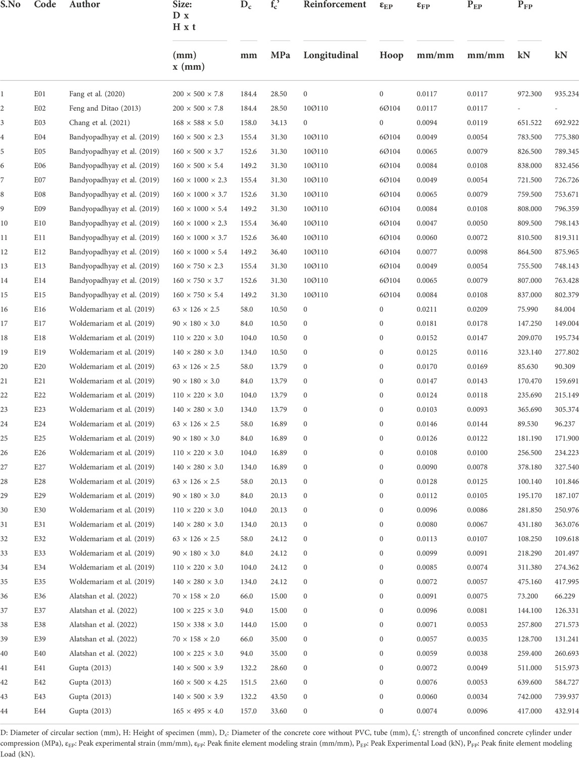
The first part of the simulated experimental work includes the comparison of the simulated stress-strain model of CFPT columns from the experimental work. A wide-ranging database with a test result of 44 CFPT columns with different unconfined concrete strength, the thickness of PVC tubes, slenderness ratios, and specimen sizes were collected from 8 different studies (Feng and Ditao, 2013; Fang et al., 2020; Chang et al., 2021; Bandyopadhyay et al., 2019; Woldemariam et al., 2019; Alatshan et al., 2022; Gupta, 2013). Experimental stress and strain value from literature for 44 CFPT columns are stipulated using ABAQUS software (ABAQUS, 2014) and compared with simulated stress and strain (Isleem et al., 2022). The summary of controlled specimens used in these investigations are these 44 CFPT specimens and their results are tabulated in Table 1.
The study is extended further to develop simulated CFPT columns wrapped with fully/partially CFRP using ABAQUS software (ABAQUS, 2014). Table 2 provides the summary of the CFRP-wrapped CFPT columns. The parameters varied are thickness, depth, and the number of layers of CFRP on the load-carrying capacity of the column. Based on the CFRP properties, the entire research work is grouped into twelve groups based on the CFRP depth and number of layers of CFRP, for controlled specimens. The depth of CFRP layers varies from 20, 30, 40, 50, 60, and 100 mm in group 1. With an increase in CFRP depth, there is a decrease in load-carrying capacity is noted. With an increase in the number of layers, the load-carrying capacity of columns increases is noted.
For group 2, for the same specimens, the CFRP total thickness and number of layers are varied, whereas the depth of CFRP is kept constant. With the increase in the number of layers, there is an increase in the load-carrying capacity of the specimen is observed. For group 3, the load-carrying capacity of CFPT columns increases with an increase in the number of layers, and the load-carrying capacity decreases with an increase in CFRP depth. Similar to group 3, group 4 has a similar load-carrying capacity behavior, but with the increase in confined concrete strength, an increase in load-carrying capacity is observed.
Group 5, shows that an increase in the number of layers increases the load-carrying capacity of CCFPT columns, whereas an increase in the depth of CFRP layers, results in a decrease in load-carrying capacity is observed. And also, an increase in the number of layers up to 40 mm depth of CFRP layers results in a decrease in the strain of CCFPT columns are noted, and after that, there is a decrease in strain value is decreased. With an increase in height of CCFPT columns, there is a decrease in load-carrying capacity for group 6 is noted, whereas an increase in confined concrete strength increases load-carrying capacity. There are three subgroups were noted for group 6, with two subgroups having different confined concrete strengths and the same height of columns whereas the third subgroup has different heights of columns with the same confined concrete strength.
For group 7, the parameters like PVC thickness, specimen height, number of layers, and CFRP depths are varied. The second highest ultimate strain value is noted in group 7 when compared to all other groups. There are two major subgroups are noted for group 8 with two different confined concrete compressive strengths. Each subgroup has three different subgroups based on the PVC thickness. Therefore, six subgroups are noted in group 8. With an increase in confined concrete strength, there an increase in the load-carrying capacity is observed. There are two major subgroups are noted for group 9 with two different confined concrete compressive strengths. There are three subgroups for the number of layers. In each sub-group, there is an increase in the depth of CFRP layers there is a decrease in load-carrying capacity is observed. With an increase in the number of layers, there is an increase in load-carrying capacity is noted. Similar to group 9, group 10 has the same trend but the PVC thickness is less. Two major groups are noted with group 10 but the behavior remains similar. The load-carrying capacity of columns increases with an increase in PVC thickness as noted in group 11 for layer 1, whereas for 3 layers the load-carrying capacity remains the same. Group 12 has four different depths of CFRP layers with an increase in depth resulting in a decrease in load-carrying capacity. An increase in PVC thickness results in an increase in the load-carrying capacity of the column is noted.
3 Finite element modelling
3.1 Element and interaction
3.1.1 Finite element type
The S4R shell element was used to model the hollow PVC tube, to accurately predict its deformation. The S4R element has six degrees of freedom at every node. However, the concrete core was simulated with a C3D8R element. Two rigid plates were modeled at the top and bottom of the composite column. The bottom plate was fixed, while the top rigid plate has the freedom to move downward to transfer axial load. Implementation of a good mesh size would lead to accurate calculation within a period.
3.1.2 Interface
The surface-to-surface contact model was employed to model the interactions between the external surface of the concrete core and the internal surface of the PVC tube. Meanwhile, hard contact interaction was utilized in the normal direction, which prevents compressive state penetration by the concrete and PVC elements. However, the interaction between the PVC and concrete was regarded as a “Tie” (Ozkilic et al., 2022). Two reference points RP1 and RP2 were attached to the rigid plates.
3.1.3 Boundary conditions and load applications
The reference point at the top rigid plate was set to have freedom of vertical displacement, while in the other directions freedom was constrained. The reference point at the bottom rigid plate was constrained in all degrees of freedom. The vertical displacement was modeled to simulate the axial loadings. For the eccentric load conditions, the axial load was applied at 20, 30, 40, and 50 away from the central axis.
3.2 Material models
3.2.1 Confined concrete
The concrete core is confined by the PVC tube. Hence, it was modeled as a confined concrete. Under load, concrete transit from the elastic stage to the plastic stage and then fails. In the elastic region, the constitutive model of the concrete was expressed by its elastic modulus,
Where
Beyond the elastic limit, transitions of concrete to the plastic region begins, which makes interaction between concrete and PVC tubes starts. At this stage, there exist interactions and contact pressure between the PVC tube’s inner surface and the outer surface of the concrete due to the plastic expansion of the concrete. In this case, a confined peak strain model Concrete Damage Plasticity Model (CDPM) in ABAQUS was used to simulate the concrete core (Raza et al., 2019; Ozkilic et al., 2021a). CDPM utilizes the two main failure criteria viz., tensile cracking and compressive crushing (Ozkilic et al., 2021b; Ozkilic et al., 2021c). The constitutive relations of the concrete were expressed by plastic flow potential, yield surface function, and softening rule/strain hardening. The plastic flow potential was expressed by the dilation angle
At the onset of loading, the constraint of the PVC tube on the concrete core was not considered, therefore, the stress state of the concrete core is comparable to the unconfined concrete. Therefore, Eq. 2 (Papanikolaou and Kappos, 2007) was used to describe the ascending stress-strain response curve till the peak stress. The strain of the confined concrete at peak first peak load (
Upon reaching the peak stress, the response curve became a plateau, which indicated the onset of the development of the plastic response stage. The plateau proceeded and the concrete core expands laterally. The lateral expansion was resisted by the PVC tube. The model proposed by Isleem et al. (2022) through multi-linear regression analysis was used to describe the strain of the confined concrete core.
3.2.2 PVC
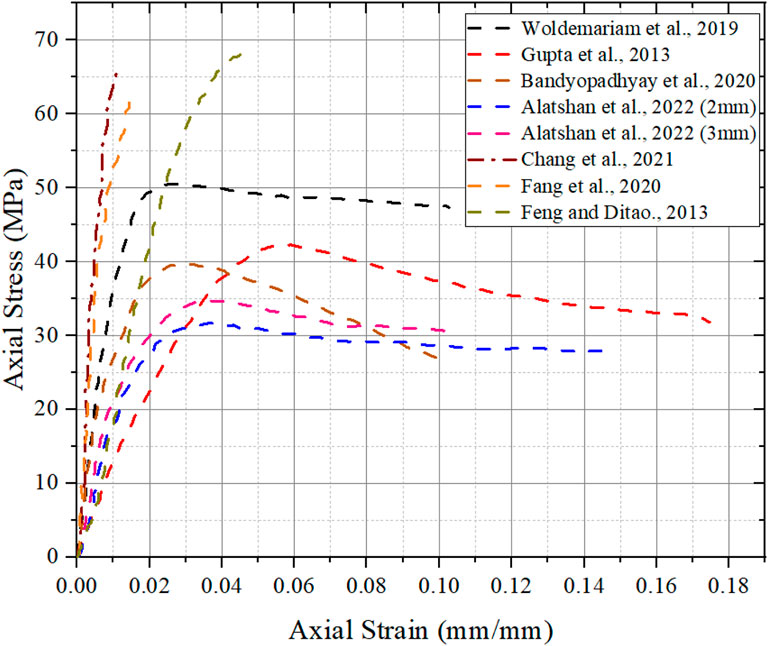
The stress-strain response and softening rule of PVC plastic would be different from that of concrete. PVC plastic is a ductile material with large strain. It is regarded as an isotropic material due to its similar properties in all directions. The PVC tube is modeled as a von mises material with isotropic hardening. For the effective modeling of the material, it is imperative to define the parameters of yield strength, Poisson ratio, elastic modulus, and inelastic strain for the elastic and plastic material definition. As reported, the test data of PVC employed are presented in Table 4; Figure 2.
3.2.3 Steel material
Steel is used for the end plates and reinforcement bars. The density of hoop and longitudinal steel used in this investigation is 7850 kg/m3. Young’s modulus of steel is 2 × 10⁵ N/mm2 and Poisson’s ratio of 0.20 is used for this investigation at the elastic stage. Whereas at the plastic stage of steel, the yield stress of steel is 500 N/mm2 and the plastic strain is zero. Reinforcement is embedded in the whole model with fractional exterior tolerance of 0.05.
3.2.4 Carbon fiber reinforced polymer
CFRP is viewed as an orthotropic material frequently. High tensile strength is noted, in the longitudinal direction and displays an elastic behavior, but the compressive strength of CFRP is almost neglected. Therefore, the CFRP properties are specified using the “LAMINA” material type. The failure mode of CFRP was the tensile fracture, so the damage behavior of CFRP must be considered. The tensile failure stress of CFRP is considered as 3612 MPa and the corresponding tensile failure strain is 0.016125 is used for this analytical investigation. Similar tensile failure stress and young’s modulus were reported by Xu et al. (2021). CFRP was chosen as the wrapped material partially/fully, with a different number of layers of the CFPT columns. The mass density of CFRP used in this investigation is 1.7 × 10⁻⁹ kg/m3 and the thickness of each layer is 20 mm. The properties of CFRP used in this investigation are tabulated in Table 5.
3.3 Boundary conditions and types of loadings
All degrees of freedom on the bottom of the columns in models are constrained. Concentric load is applied on the top of the columns along the main axis of the column under displacement mode. Boundary conditions on the top surfaces with displacement on the X-axis and Y-axis are zero. On the top of the column specimen, the displacement along the main axis is allowed only. Whereas rotation along all three axes is set to be free. For the bottom surface, the displacement and rotation are arrested on all three axes.
3.4 Meshing
The sweep technique creates a three-dimensional mesh by moving a two-dimensional mesh along a sweep path (3DS., 2014). Elements of 10 mm in size and the Sweep technique have been used for the concrete core. Elements of 15 mm and 20 mm in size and the Sweep Technique have been used for PVC pipe in columns with and without gaps at two ends, respectively. Figure 3 shows the finite element modeling for CFPT tubes.
4 Model validation
4.1 Failure modes
The comparison of the experimental data and numerical results presents the accuracy and precision of the finite element model for validation. Figure 4 presents the comparison of the test results and numerical simulations. It can be observed that there is a correlation in the failure mode.
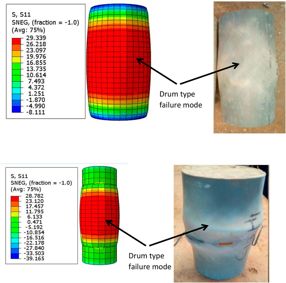
FIGURE 4. Comparison of failure mode of FE and Experimental results. Note: Experimental failure modes were reported by Woldemariam et al. (2019).
4.2 Discussions of experimental and model results
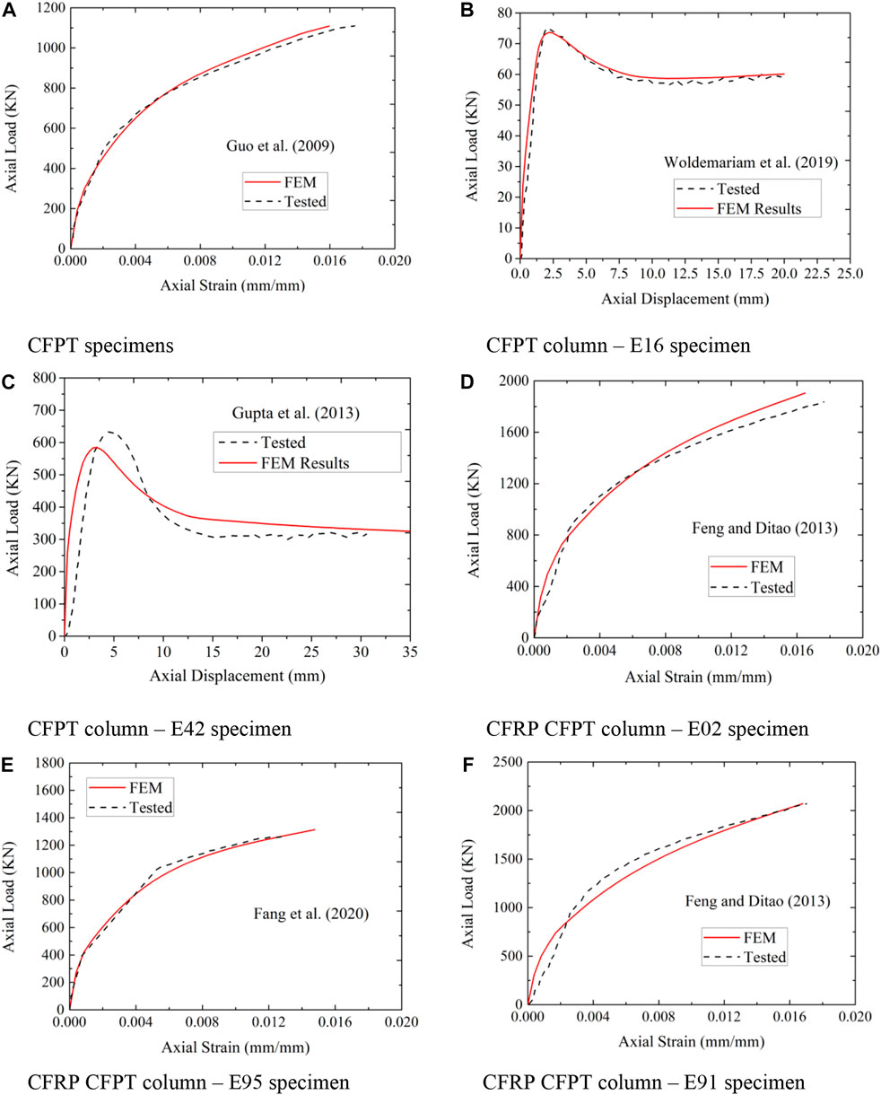
In the literature, it is noted that the results provided by FE models are higher when compared to that of experimental test value (Isleem et al., 2022). Figure 5 represents the axial strain load curves obtained from experimental testing and FE simulation results for specimens with and without CFRP wrapping on CFPT columns selected from (Guo et al., 2008; Woldemariam et al., 2019; Gupta, 2013; Feng and Ditao, 2013). A comparison of results displayed in Figures 5A–F is selected based on variations in different parameters from different authors of literature. It is also noted that the experimental results and simulation results are having an almost similar pattern for the axial strain-axial load curve and it is also confirmed in the literature (Isleem et al., 2022).
Both CFPT (Figures 5A–C) and CCFPT (Figures 5D–F) show a similar pattern of axial load–strain curve for both experimental and FE results.
5 Test results and discussions
5.1 Failure modes
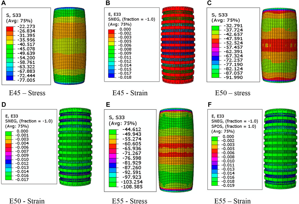
Two different types of specimens are simulated with and without longitudinal reinforcement. Specimens are wrapped with CFRP at different depths and layers. When a specimen without longitudinal reinforcement is loaded axially, the cracks are initiated at mid-height when the peak load is reached. After peak load carrying capacity was reached, followed by spalling of concrete but it is prevented by CFRP wraps until rupture as shown in Figures 6A–F. Aksoylu et al., 2022 compared the experimental and numerical investigation of load bearing capacity of FRP composites.
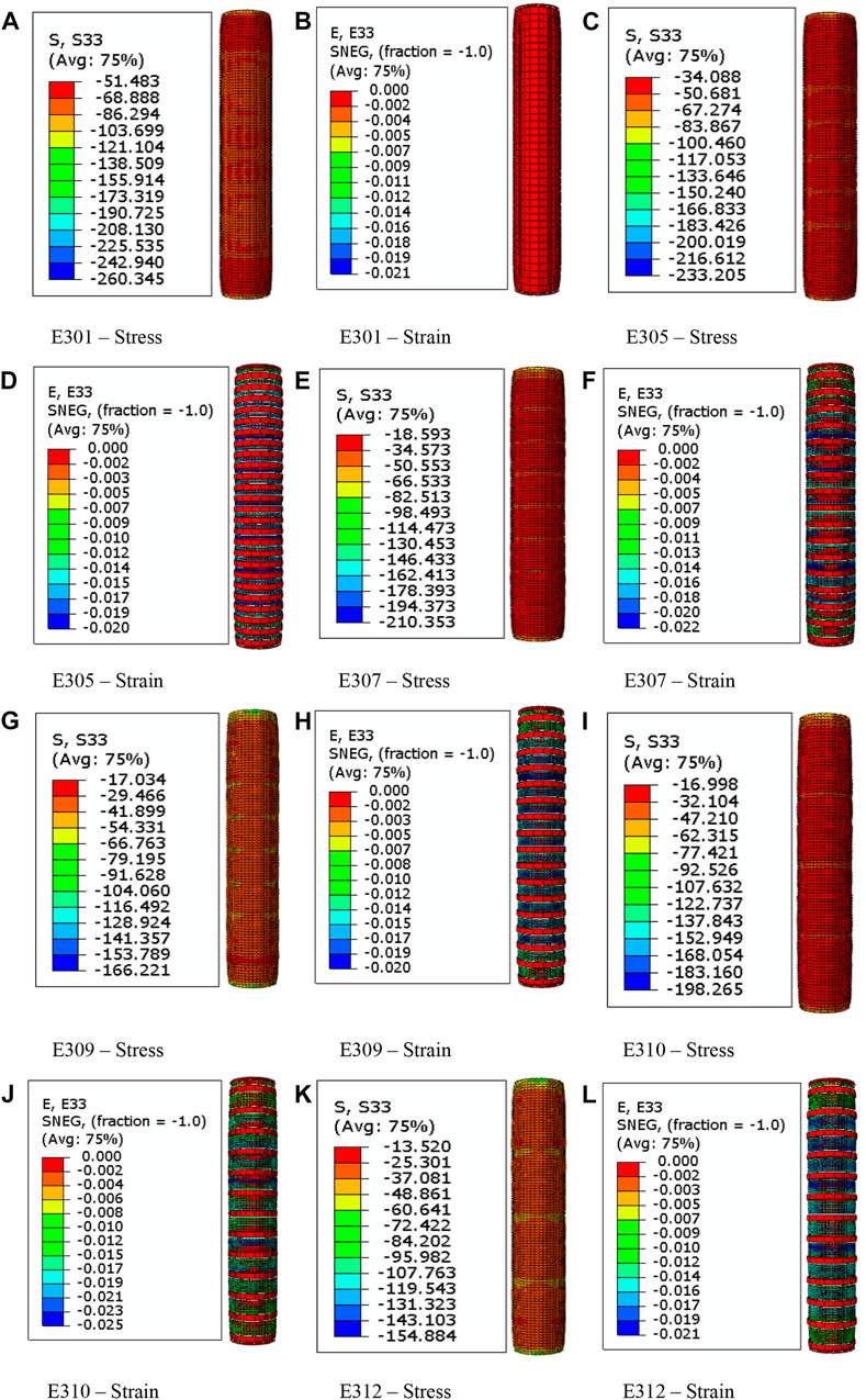
The failure mode of unconfined CFPT and CCFPT columns was first initiated with mid-height cracks. On further loading, the maximum load-carrying capacity is reached, followed by concrete spalling and buckling of longitudinal reinforcement as shown in Figures 7A–L. Once bucking of longitudinal reinforcement was reached but buckling of columns is prevented until the eventual rupture of the CFRP wraps. At the mid-height of the specimens, the rupture of the wraps originated around the corners of the column sections. Similar behavior of failure modes is reported in the literature (Wang and Wu., 2008; Abbasnia et al., 2012).
5.2 Axial load–axial strain
Specimens having CFRP wraps leads to an increase in the axial strength but with a very low rate likened to the axial strain. Peak axial strain varied more than thrice that of unconfined concrete and these results are consistent with other results reported in the literature (Hany et al., 2016; Isleem et al., 2018a). Specimens unreinforced by CFRP wrapping experienced gains in the peak strain, whereas there is no observed improvement in their peak strain. Confined specimens displayed a decreased strength due to the low resistance of the CFRP wrap against the dilation and lateral expansion of the core concrete. Stress-strain test results correspond to specimens confined with a similar number of CFRP layers wrapped with different hoop reinforcements showing different behavior. It is also noted that the axial stress and strain for the reinforced and unreinforced column shows different behavior. Confinement provided by the external CFRP wrapping decreases as the cross-sectional specimen column increases and is also confirmed by Isleem et al. (2018b). An increase in the shear capacity of the reinforced concrete section with CFRP wrapping is reported by Mhanna et al. (2020).
6 Influence of the tested parameters
6.1 Effect of CFRP hoop spacing
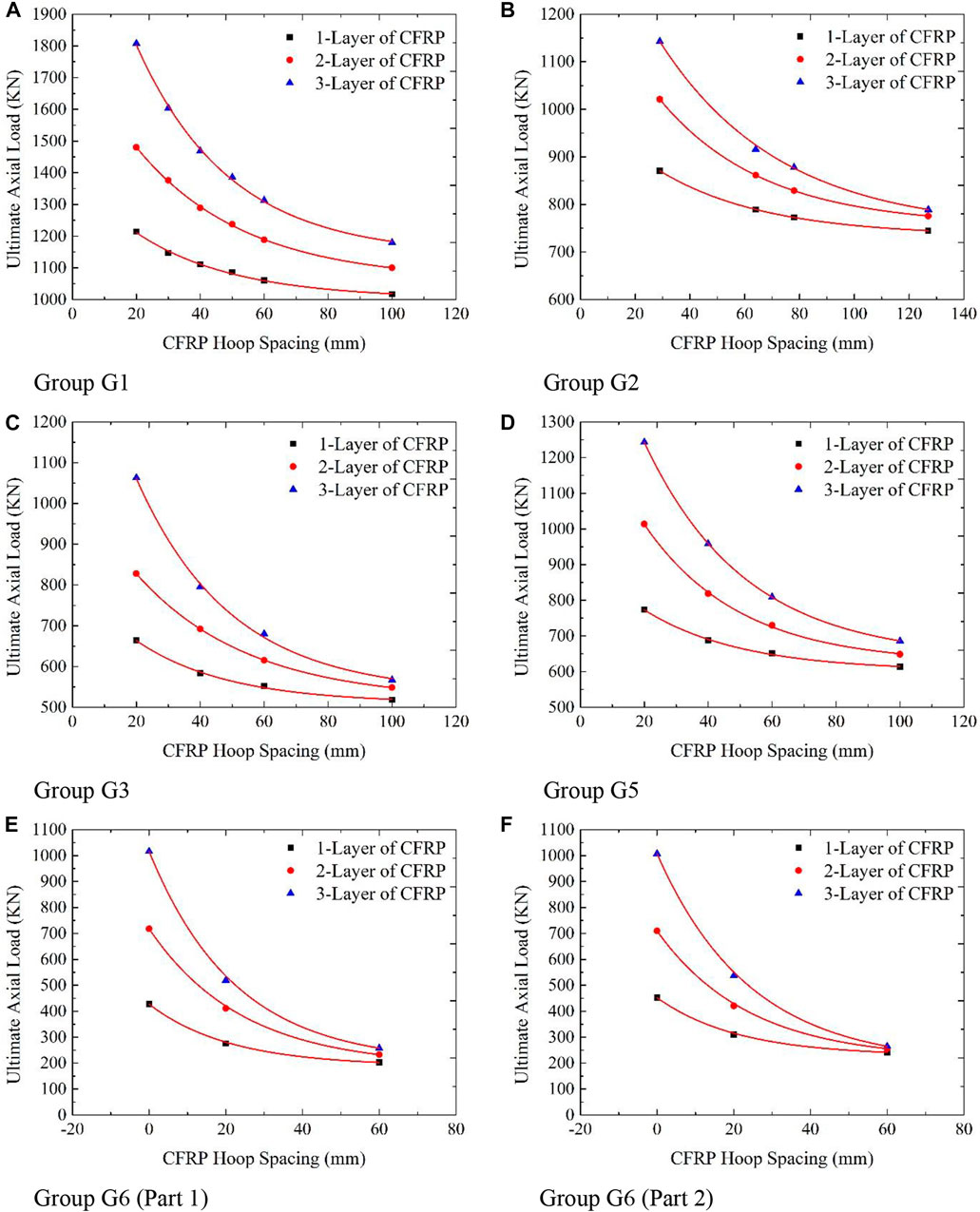
The ultimate axial load-carrying capacity increases with the increase in the number of CFRP layers as noted in Figure 8. Additionally, an increase in CFRP hoop spacing results in a decrease in ultimate axial load-carrying capacity. When CFRP thickness increased from 20 mm to 100 mm, the ultimate axial load decreased from 1807.41 kN to 1179.74 kN for 3-layer CFRP, but for 1-layer CFRP, the ultimate axial load decreased from 1214.75 kN to 1016.74 kN is reported from Figure 8A. A decrease in the ultimate axial load is in the range of 1.53, 1.35, and 1.19 times for 3-layer, 2-layer, and 1-layer CFRP from 20mm to 100 mm hoop spacing. From Figure 8B, it is noted that the ultimate axial load decreases in the range of 1.45, 1.32, and 1.17 times for 3-layer, 2-layer, and 1-layer CFRP from 29 mm to 127 mm hoop spacing. Ultimate axial load decreases in the range of 1.87, 1.51, and 1.28 times for the 3-layer, 2-layer and 1-layer CFRP from 20mm to 100 mm hoop spacing for group 3 is noted in Figure 8C.
From Figure 8D, it is noted that the ultimate axial load decreases in the range of 1.81, 1.56, and 1.26 times for 3-layer, 2-layer, and 1-layer CFRP from 20 mm to 100 mm hoop spacing. Ultimate axial load decreases in the range of 3.94, 3.08, and 2.11 times for the 3-layer, 2-layer and 1-layer CFRP from 0mm to 60 mm hoop spacing for group 6 (part 1) is noted in Figure 8E. From Figure 8F, it is noted that the ultimate axial load decreases in the range of 3.80, 2.77, and 1.87 times for 3-layer, 2-layer, and 1-layer CFRP from 0mm to 60 mm hoop spacing. From Figure 8, the following results are summarized:
• The effect of the slenderness ratio is more on the hoop spacing in terms of the ultimate axial load
• The impact of PVC tube thickness is moderate on the hoop spacing in terms of ultimate axial load
• A slight influence of confined concrete strength on the hoop spacing in terms of ultimate axial load
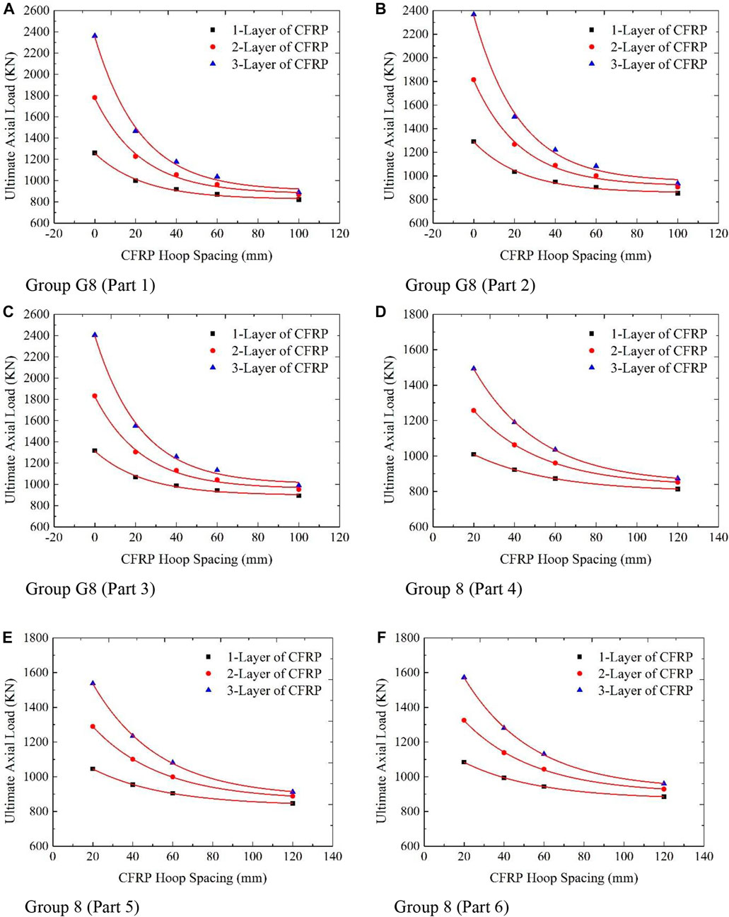
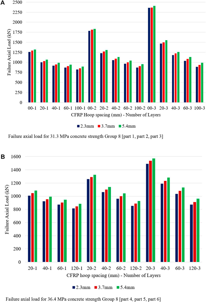
When hoop spacing is increased from 0 mm to 100 mm, an ultimate axial load decrease from 1260.62 kN to 820.04 kN, 1781.51 kN–866.80 kN, and 2361.59 kN–889.18 kN for 1-layer, 2-layer, and 3-layer CFRP is observed from Figure 9A. Decreases in the ultimate axial load for 1-layer, 2-layer, and 3-layer CFRP are in the range of 1.54, 2.05, and 2.65 times for 0 mm when compared to 100 mm hoop spacing. From Figure 9B, it is noted that the decrease in the ultimate axial load for 1-layer, 2-layer, and 3-layer CFRP is in the range of 1.51, 2.01, and 2.53 times for 0 mm when compared to 100 mm hoop spacing.
A decrease in the failure axial load for 1-layer, 2-layer, and 3-layer CFRP is in the range of 1.47, 1.92, and 2.43 times for 0 mm, when compared to 100 mm hoop spacing, is observed in Figure 9C. With an increase in PVC thickness, there is an increase in failure axial load, and also, the rate of reduction of failure axial load to increase in CFRP layers is slow is observed. From Figure 9D, it is noted that the decrease in the failure axial load for 1-layer, 2-layer, and 3-layer CFRP is in the range of 1.24, 1.48, and 1.71 times for 20 mm when compared to 120 mm hoop spacing.
A decrease in the failure axial load for 1-layer, 2-layer, and 3-layer CFRP is in the range of 1.24, 1.45, and 1.68 times for 20 mm, when compared to 120 mm hoop spacing, is observed in Figure 9E. From Figure 9F, it is noted that the decrease in the failure axial load for 1-layer, 2-layer, and 3-layer CFRP is in the range of 1.23, 1.43, and 1.64 times for 20 mm when compared to 120 mm hoop spacing. From Figure 9, the following results are summarized:
• The effect of PVC tube thickness is more on the hoop spacing in terms of failure axial load under all other factors are constant
• The impact of the confined concrete load is moderate on the hoop spacing in terms of failure axial load and all other factors are constant.
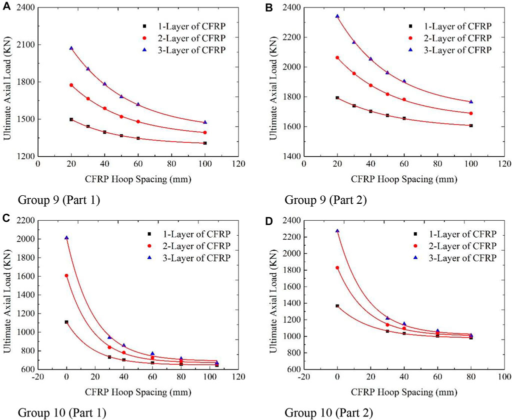
The effect of CFRP hoop spacing on the failure axial load for the CCFPT columns with reinforcement is shown in Figure 10. A decrease in the failure axial load for 1-layer, 2-layer, and 3-layer CFRP is in the range of 1.15, 1.27, and 1.41 times for 20 mm, when compared to 100 mm hoop spacing, is observed in Figure 10A. From Figure 10B, it is noted that the decrease in the failure axial load for 1-layer, 2-layer, and 3-layer CFRP is in the range of 1.12, 1.22, and 1.33 times for 20 mm when compared to 100 mm hoop spacing. A decrease in the failure axial load for 1-layer, 2-layer, and 3-layer CFRP is in the range of 1.72, 2.45, and 3.01 times for 0 mm, when compared to 105 mm hoop spacing, is observed in Figure 10C. From Figure 10D, it is noted that the decrease in the failure axial load for 1-layer, 2-layer, and 3-layer CFRP is in the range of 1.39, 1.83, and 2.25 times for 0 mm when compared to 80 mm hoop spacing. From Figure 10, the following results are summarized:
• Increase in failure load carrying capacity of a specimen with reinforcement, when confined concrete strength is increased.
• The effect of spacing between main longitudinal bars and hoop bars on the failure load carrying capacity of specimens is noted.
Confinement of CFRP wraps directed to an increase in the axial load but with a very low rate compared to the axial strain is already reported by Isleem et al. (2018a). It is also reported that the addition of CFRP wrapping not only increases the lateral confinement but also the compressive strength and ductility could be improved drastically (Jin et al., 2020). Usage of the optimum amount of CFRP in reinforced concrete structures (Gemi et al., 2022b).
6.2 Effect of CFRP depth
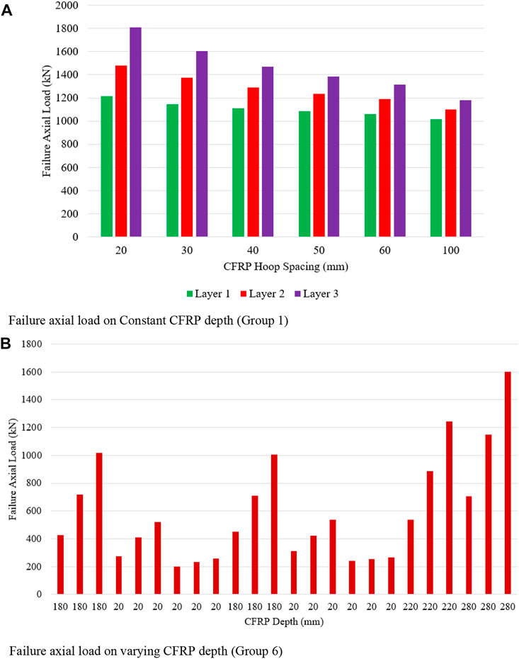
The influence of the overall depth of CFRP on the failure axial load of unreinforced CFPT columns is observed in two different scenarios: 1. CFRP depth is maintained as constant throughout the depth of the specimen (Figure 11A) and 2. CFRP depth is varied throughout the depth of the specimen (Figures 11B, 12A). CFRP depth is kept as constant as 20 mm for group 1 but CFRP hoop spacing is kept as clear to clear distance between CFRP wrapping but it is varied from 20 mm to 100 mm. When the number of layers is increased from 1 to 2 and 3 the failure axial load is increased to 21.86% and 48.79% as compared to layer 1. CFRP hoop spacing is increased as 30 mm, 40 mm, 50 mm, 60 mm, and 100 mm for layer 1, and the failure axial load is increased by 5.63%, 8.54%, and 10.59% when compared to 20 mm CFRP hoop spacing.
Whereas for layer 2, CFRP hoop spacing increased as 30 mm, 40 mm, 50 mm, 60 mm, and 100 mm, the failure axial load increased by 7.07%, 12.92%, 16.43%, 19.71%, and 25.68% compared to 20 mm CFRP hoop spacing. When the number of layers is further increased to layer 3, CFRP hoop spacing is increased as 30 mm, 40 mm, 50 mm, 60 mm, and 100 mm, and failure axial load increased by 11.25%, 18.74%, 23.35%, 27.35%, and 34.73% compared to 20 mm CFRP hoop spacing. From this, it can be concluded, that at constant CFRP depth, with an increase in some layers as layer 3, the increase in failure axial load is higher when compared to layer 1.
CFRP depth is increased from 20 mm to 180 mm, there is an increase in the failure axial load from 202.68 kN to 1016.14 kN for layer 1 is observed. For layer 3, the failure axial load increases from 257.78 kN to 1016.14 kN for group 6 (part 1) for the confined concrete compressive load as 10.5 MPa with CFRP hoop spacing as 20 mm, 60 mm, and 0 mm. An increase in confined concrete compressive strength of 24.12 MPa, there is an increase in failure axial load for group 6 (part 2) is noted. When CFRP wrapping depth is increased there is an increase in failure axial load is noted in Figure 12B. Even though CFRP wrapping depth is kept constant and hoop spacing is increased means the failure axial load also increased but the rate of failure axial load is less.
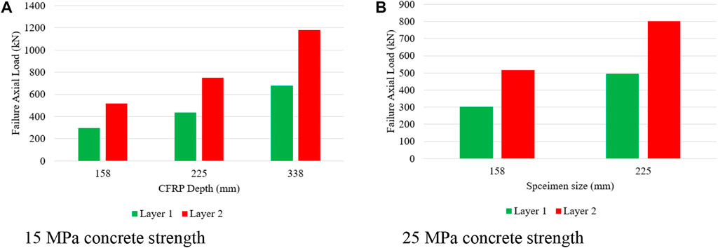
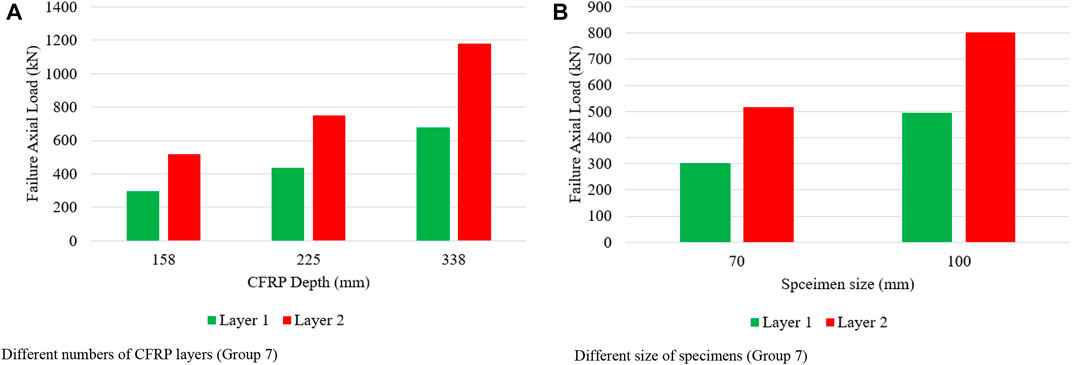
With increase in CFRP depth from 158 mm to 338 mm, the failure axial load increased from 294.62 kN to 679.43 kN for layer 1, whereas the failure axial load increased from 518.81 kN to 1178.64 kN for layer 2 having confined concrete strength as 15 MPa. Whereas an increase in confined concrete strength to 25 MPa, the failure axial load is increased from 301.04 kN to 495.83 kN for layer 1 and when the number of layers is increased to 2, the failure axial load is increased from 515.09 kN to 802.39 kN. From Figure 12, it is noted that the increase in confined concrete strength results in an increase in the rate of the failure axial load from 1.48 to 1.65 times for layer 1, whereas the rate of the failure axial load increases from 1.45 to 1.56 times for layer 2. It is also noted that with an increase in the number of layers, there is a decrease in the rate of failure axial load. It is also reported in the literature, that the higher failure axial load is noted for 20 mm CFRP depth for circular columns (Vasumathi et al., 2014).
6.3 Effect of PVC tube thickness
When PVC tube thickness is increased from 2.3 mm to 5.4 mm, failure axial load increased from 1260.62 kN to 820.04 kN for layer 1 for full CFRP wrapping to 100 mm CFRP hoop spacing. When the number of layers is increased to layer 2, the failure axial load increases from 1781.51 kN to 866.80 kN for full wrapping to 100 mm CFRP hoop spacing. Failure axial load increased from 2361.59 kN to 889.18 kN for full wrapping to 100 mm CFRP hoop spacing for CFRP layer 3. From Figure 13A, it is noted that for layer 2, the failure axial load increased from 1.41 to 1.06 times when compared to layer 1. Whereas for layer 3, the failure axial load increased from 1.87 to 1.08 times for full CFRP wrapping to 100 mm CFRP hoop spacing for group 8 (part 1, part 2, and part 3).
When PVC tube thickness increased from 2.3 mm to 5.4 mm, the failure axial load increased from 1009.45 kN to 1084.09 kN for 20 mm CFRP hoop spacing having CFRP layer 1. Whereas for 120 mm CFRP hoop spacing, the failure axial load increased from 813.17 kN to 884.89 kN. For layer 2, the failure axial load increased from 1257.69 kN to 1324.90 kN for 20 mm CFRP hoop spacing, and for 120 mm CFRP hoop spacing, the failure axial load increased from 852.02 kN to 928.59 kN. For layer 3, the failure axial load increased from 1492.94 kN to 1572.69 kN for 20 mm CFRP hoop spacing, and for 120 mm CFRP hoop spacing, the failure axial load increased from 873.3 kN to 960.03 kN.
When the number of layers is increased from layer 2 to layer 3, the failure axial load increased by 1.25 times to 1.48 times when compared to layer 1 for 20 mm CFRP hoop spacing. Whereas, for 120 mm CFRP hoop spacing, when the number of layers is increased as 2 and 3, the failure axial load increased 1.22 times and 1.45 times as noted in Figure 13B. An increase in PVC tube thickness results not only increases the failure load-carrying capacity of columns but also influence the stress-strain behavior of the column itself (Abdulla, 2020; Oyawa, et al., 2016). The confinement action of CCFPT columns is reliant on the concrete infill behavior to dilate when loaded, as well as the circular stiffness of the confining member to restrain the enlargement (Oyawa, et al., 2016).
6.4 Effect of column’s slenderness ratio
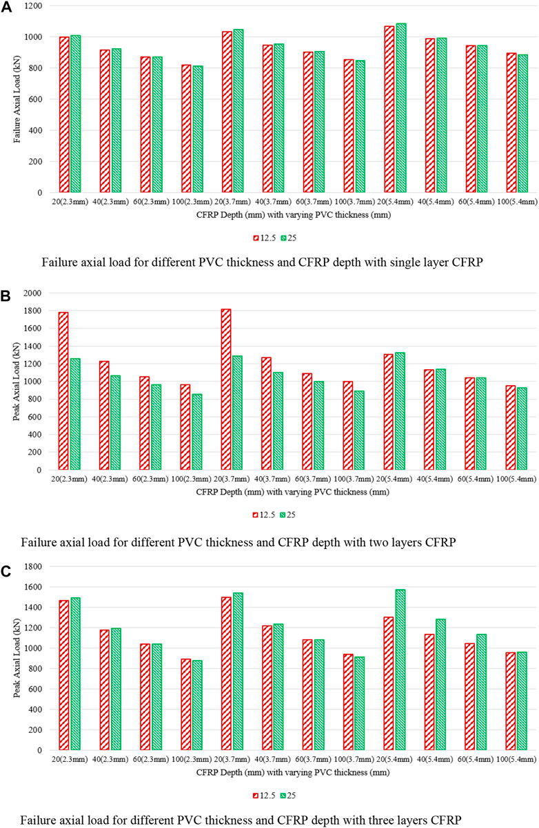
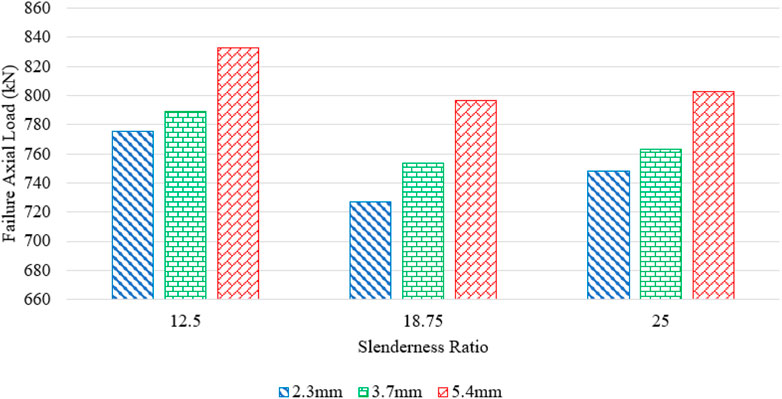
With an increase in the slenderness ratio, there is an increase in axial load is observed in Figure 14A. Failure axial load for slenderness ratio 12.5 with the CFRP hoop spacing as 20, 40, 60, and 100 mm, the load decreases as 999.39, 917.70, 869.74, and 820.04 kN. When the slenderness ratio is increased to 25, the failure axial load increases by 1.010, 1.005, 1.003, and 0.992 times that of the failure axial load for a slenderness ratio of 12.5 for a PVC tube thickness of 2.3 mm. When PVC tube thickness is increased to 3.7 mm, the failure axial load increases by 1.012, 1.006, 1.002, and 0.993 times for a slenderness ratio of 25 when compared to that of the column having a slenderness ratio of 12.5. On further increasing PVC tube thickness to 5.4 mm, the failure axial load increases by 1.015, 1.007, 1.002, and 0.990 times for a slenderness ratio of 25 when compared to that of columns having a slenderness ratio of 12.5. From this, it can be concluded that, for single-layer CFRP, there is a mild increase in failure axial load when the slenderness ratio is increased twice.
For layer 2, failure axial load for slenderness ratio 12.5 with the CFRP hoop spacing as 20, 40, 60, and 100 mm, the load decreases as 1781.51, 1227.56, 1055.10, and 962.25 kN. When the slenderness ratio is increased to 25, the failure axial load is decreased to 0.706, 0.866, 0.911, and 0.885 times the failure axial load for a slenderness ratio of 12.5 for a PVC tube thickness of 2.3 mm. When PVC tube thickness is increased to 3.7 mm, the failure axial load is decreased to 0.710, 0.868, 0.918, and 0.888 times for a slenderness ratio of 25 when compared to that of a column having a slenderness ratio of 12.5. On further increasing PVC tube thickness to 5.4 mm, the failure axial load is increased as 1.016, 1.006, 1.001, and 0.75 times for a slenderness ratio of 25 when compared to that of columns having a slenderness ratio of 12.5. When the number of CFRP layers is 2, with CFRP depth of 20 mm and 40 mm and PVC tube thickness of 3.7 mm, there is a difference in failure axial load is noted.
From Figure 14B, when CFRP depth is 20 and 40 mm, there is a difference in failure axial load for slenderness ratio is noted. It can be concluded that, with an increase in CFRP depth from 20 mm to 100 mm, there is a decrease in failure axial load is noted with an increase in slenderness ratio. The rate of reduction of failure axial load varies for varying PVC tube thicknesses used.
For three layers of CFRP, the failure axial load behavior is different when compared to two and single-layer CFRP as noted in Figure 14C. Decrease in failure axial load for columns about 6.27% and 3.51% for slenderness ratio of 18.75 and 25 for PVC tube thickness 2.3 mm when compared to columns slenderness ratio of 12.5. Whereas a decrease in failure axial load for 3.7 mm and 5.4 mm is 4.52%, 3.28% and 4.34% and 3.61% for columns having a slenderness ratio of 25 when compared to columns slenderness ratio of 12.5. With an increase in slenderness ratio and increase in PVC thickness, there is a decrease in failure axial load is observed. Whereas from Figure 15, it is noted that with an increase in slenderness ratio, there is an increase in failure axial load and also the rate of increase in failure axial load is slow with an increase in PVC tube thickness observed. With an increase in the slenderness ratio, there is a decrease in the failure axial load capacity of CFPT as reported by Huang, et al. (2022). On a higher slenderness ratio, failure axial load reduction is due to the full utilization of the PVC and concrete material (Huang et al., 2022).
6.5 Effect of CFRP layer
The increase in failure axial load of a column of about 76.09%, 72.69%, and 73.48% for 158, 225, and 338 mm CFRP depth for layer 2, when compared to layer 1 CFRP wrapping, is observed from Figure 16A.
An increase in failure axial load of column specimens of about 71.10% and 61.83% for column specimen diameter as 70 mm and 100 mm for CFRP layer 2 when compared to CFRP layer 1 is observed in Figure 16B. An increase in specimen size with an increase in the number of layers also increases failure axial load. When the number of layers is increased, the failure axial load and failure axial strain of the column specimen is increased as reported by Fakharifar and Chen. (2016). Confining effect of CCFPT increases with an increase in CFRP layers as observed by Jiang et al. (2014).
6.6 Effect of confined concrete strength
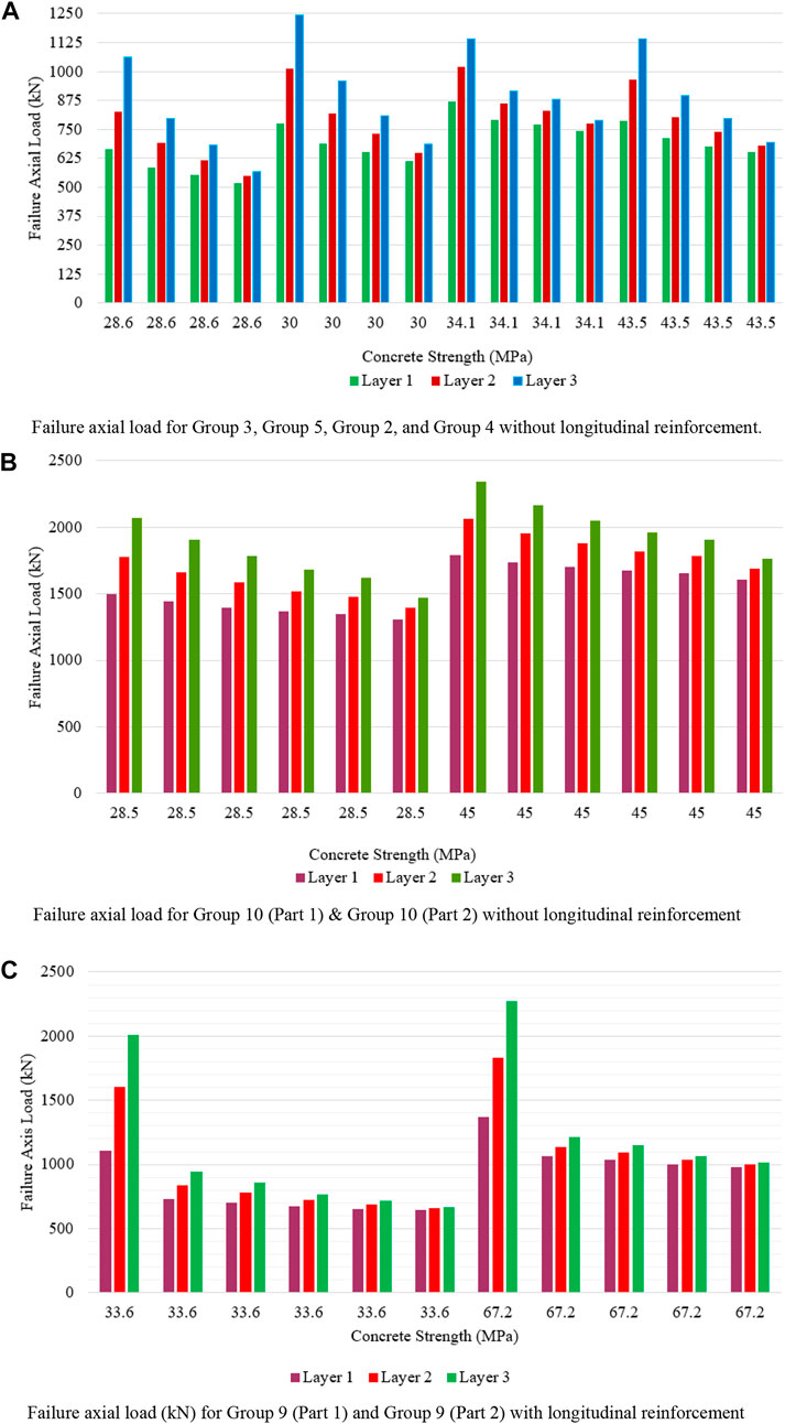
An increase in hoop spacing as 20, 40, 60, and 100 mm, for layer 2 results in an increase in failure axial load of about 24.60%, 18.68%, 11.54%, and 5.80% then layer 1 for 28.6 MPa concrete strength is observed from Figure 17A. Whereas for 30 MPa confined concrete strength, there is an increase in failure axial load of 31.00%, 18.99%, 12.11%, and 5.72% for CFRP layer 2 when compared to CFRP layer 1.
On further increase in 34.1 MPa confined concrete strength, there is an increase in failure axial load of 17.25%, 9.11%, 7.30%, and 4.14% for CFRP layer 1 when compared to CFRP layer 2. Increase in confined concrete strength to 43.1 MPa, there is an increase in failure axial load of 22.45%, 12.65%, 9.71%, and 4.04% for CFRP layer 1 when compared to CFRP layer 2. For hoop spacing as 20, 40, 60, and 100 mm, layer 3 results in an increase in failure axial load of about 59.99%, 36.39%, 23.26%, and 9.46% then layer 1 for 28.6 MPa confined concrete strength. On the increase of confined concrete strength to 30 MPa for CFRP layer 3, there is an increase in failure axial load as 60.66%, 39.35%, 24.32%, and 11.83% then CFRP layer 1. On further increase in confined concrete strength to 34.1 MPa for layer 3, there is an increase in failure axial load as 31.21%, 16.00%, 13.59%, and 5.95% then CFRP layer 1. When confined concrete strength is increased to 43.5 MPa for layer 3, there is an increase in failure axial load as 44.86%, 25.63%, 17.80%, and 6.13% then CFRP layer 1 is observed.
It can be observed that the rate of increase in failure axial load is decreased with an increase in confined concrete strength observed for all CFRP layers from Figure 17B. The increase in failure axial load was 45.05%, 14.30%, 11.30%, 7.74%, 4.78%, and 2.01% for CFRP layer 1 for hoop spacing as 0, 30, 40, 60, 80, and 105 mm for 33.6 confined concrete strength then CFRP layer 2 is noted. On the further increase of confined concrete strength to 67.2 MPa for layer 3, there is an increase in failure axial load to 81.54%, 28.75%, 21.93%, 14.62%, and 9.21% then CFRP layer 1. With an increase in the number of layers from layer 1 to layer 3, there is an increase in axial load as twice observed in Figure 17B. When there is an increase in confined concrete strength twice, there is a decrease in failure axial load as twice is noted.
For 28.5 MPa confined concrete strength, for hoop spacing of CFRP layer 2 as 20, 30, 40, 50, 60, and 120 mm, failure axial load increased as 18.50%, 15.53% 13.79%, 11.19%, and 6.55% then layer 1 is observed from Figure 17C. For hoop spacing of CFRP layer 3 as 20, 30, 40, 50, 60, and 120 mm, failure axial load increases by 38.26%, 32.09%, 27.79%, 22.90%, 20.16% and 12.69% then layer 3 is observed for 28.5 confined concrete strength. When there is an increase in confined concrete strength to 45 MPa, the rate of increase in failure axial load is decreased when compared to 28.5 MPa confined concrete strength. From this, it is concluded as an increase in confined concrete strength results in an increase in failure axial load but the rate of increase of load is decreased.
7 Analytical modelling
The analytical expression for the confined concrete relates to the concrete strength, PVC material, hoop reinforcement, and CFRP properties. In particular, the models are proposed to calculate the failure stress which corresponds to important parameters.
7.1 Effective lateral confinement pressure
Experimental and FEM tests on CFPT columns have shown that failure stress fcc, is influenced by the longitudinal reinforcing bars, hoop reinforcement bars, and PVC used. Hence, it is necessary to develop a model for determining the failure stress using all these parameters utilizing dimensionless parameters as reported by Wang et al. (2012a). Failure strain of CFRP, the effective rupture strain (εfe) is the most significant. Hence, rupture strain is calculated;
Similar to Isleem et al. (2018a), there are four different dimensionless parameters are used to develop a model. One more dimensionless parameter was introduced for CFRP as per Hany et al. (2016). Relative to the unconfined compressive strength of concrete, the dimensionless parameters for the PVC (λpvc), hoop reinforcement (λh), longitudinal reinforcement (λl), CFRP reinforcement (λCFRP) are introduced as follows
Where,
7.2 Confinement ratio
An analytical model that considers the influence of the various parameters on CFRP confinement provided to circular PVC columns is now introduced. Ultimate stress fcc and ultimate strain εcc denote the stress and strain at CFRP rupture failure correspondingly, and they are the two most significant parameters for the stress-strain model of CFRP-confined concrete. The relationship that relates the ultimate stress of CFRP-confined concrete to the various parameters that would influence its value is mentioned usually as the ultimate strength model. So, in the literature, the relationship between unconfined concrete to confined concrete and longitudinal reinforcement to confined concrete is reported as a linear relationship based on the experimental tests (Wang et al., 2012c).
The following expressions for the failure stress, which depend on the three different dimensionless parameters and slenderness ratio were performed using MINITAB and obtained an R2 value of 0.95. Z is the clear spacing between the CFRP wrapping used for the analytical model.
The effect of the ratio of CFRP wrapping spacing and height of the specimen on the dimensionless parameter λCFRP separately; λCFRP and λPVC respectively are shown in Eqs 8, 9.
7.3 Estimation of CFRP for sufficiently confined concrete
It is known that the effectiveness of CFRP confinement is considerably influenced by three dimensionless parameters which are already discussed in the previous paragraph. Based on multi-parameter regression analysis performed on the test database of 265 specimens, as shown in Figures 18A,B the following expressions (Eqs 10, 11) for assessing the effective CFRP confinement for circular CCFPT columns are therefore proposed, in which the correlation coefficient R2 is 94.44%. This relationship helps to define the lightly confined as a modified confined ratio (MCR) less than 0.39. Therefore, this limit should not be exceeded in practice because it is an ineffective use of CFRP wrap around concrete-filled PVC tube columns.
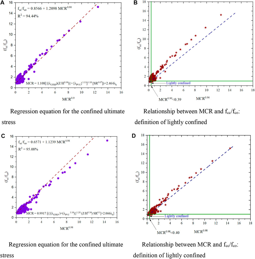
FIGURE 18. Relationship between MCR and fcc/fco from Eq. 5 (A) and (B) and MCR and fcc/fco from Eq. 6 (C) and (D).
Another multi-parameter regression analysis was performed on the test database and relationships have arrived as shown in Figures 18C,D those relationships are stated in Eqs 12, 13.
For assessing the effective CFRP confinement CCFPT columns are therefore proposed, in which the corresponding coefficient of relation is obtained as 95.08%.
8 Evaluation of exiting strength models
The precision of the proposed confinement model for PVC-CFRP columns and other pertinent models accessible in the previous literature was evaluated (Isleem et al., 2022) using two statistical indicators–the average absolute error (AAE) and the mean square error (MSE), are given by
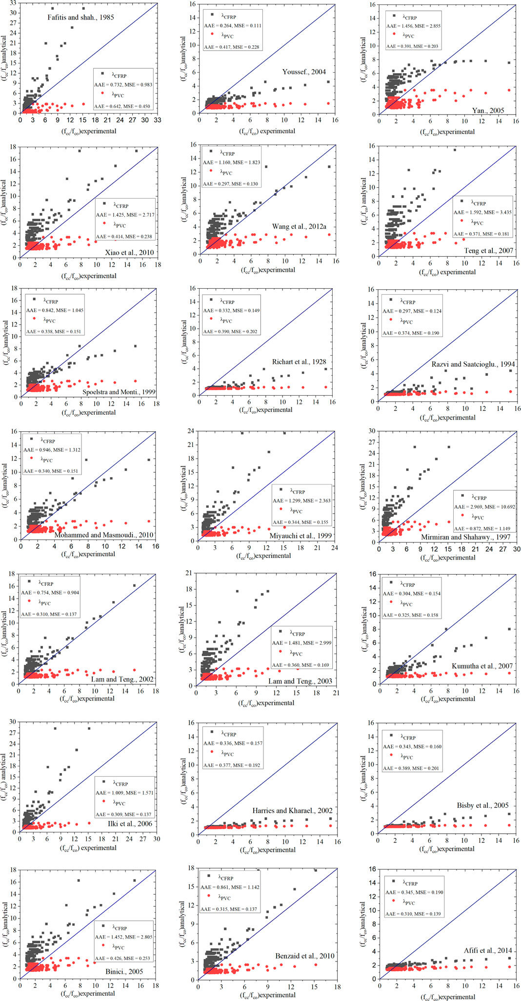
Where, Modi is the model value and expi is the analytical value obtained from the model and experimental measured from specimen i and ns is the total number of test specimens. To compare the different models available for CFRP-wrapped columns and assess their precision in predicting the ultimate strengths. Figure 19 shows a comparison between the analytical and experimental results for the required specimens listed in Table 2. Another comparison of the models available in PVC CFRP-wrapped columns and evaluate their accuracy in predicting the ultimate strengths are shown in Figure 20. Different models from the literature available for CFRP wrapped and CFPT columns show poor relation when compared to the model proposed in Eqs 10, 12.
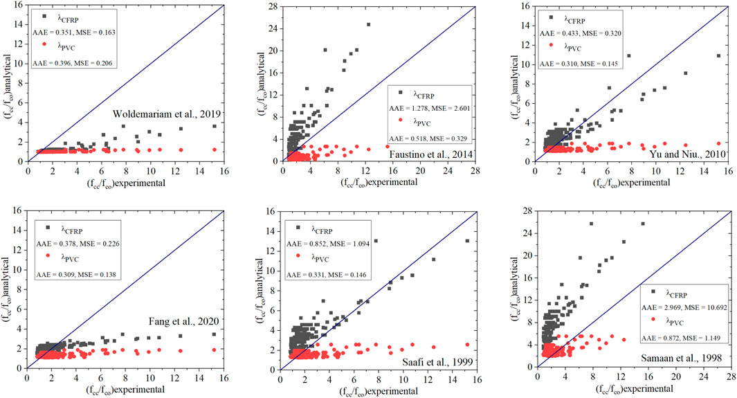
FIGURE 20. Evaluation of existing models (based on PVC CFRP wrapped models) against the test database.
9 Conclusion
In this study, simulated work on CFPT columns was done to check the appropriateness and concert of CFPT columns for structural applications is analyzed. We took 44 specimens from the literature to determine the ultimate load and ultimate strain from FEM software. CFPT columns are wrapped with CFRP fully or partially for both reinforced or unreinforced specimens and simulated using FEM software to determine the ultimate axial load and ultimate axial strain. Analytical models are developed for predicting ultimate axial load and ultimate axial strain and validated using models available in the literature. Based on the research, the following conclusions are made:
• An increase in hoop spacing results in decreases in ultimate axial load. The rate of ultimate axial load decreases with an increase in the number of layers.
• For constant depth of CFRP layer, the ultimate axial load decreases with increased hoop spacing
• For varying depths of the CFRP layer, the ultimate axial load increases with an increase in CFRP layer depth
• An increase in the number of layers increases the ultimate axial load increasing with an increase in PVC tube thickness
• An increase in hoop spacing of the CFRP wrap layer results in the ultimate axial load decrease with an increase in PVC tube thickness
• No clear conclusion can be drawn for the slenderness ratio of the column, for the ultimate axial load
• An increase in the number of CFRP layers results increase in ultimate axial load, with an increase in CFRP depth and column specimen size
• An increase in confined concrete strength increases the ultimate axial load.
• The ultimate stress model is developed for CFRP CFPT columns with help of dimensionless parameters
• The threshold limit for the Modified Confined Pressure ratio for CFRP CFPT columns is developed
This kind of new composite structure has a specific area of application in the construction field subjected to severe exposure conditions of columns and subjected to high lateral loading. CFRP CFPT columns provide a better solution for the columns subjected to lateral loading and poor durability conditions.
Data availability statement
The raw data supporting the conclusion of this article will be made available by the authors, without undue reservation.
Author contributions
Conceptualization: HI, investigation: HI and PJ, methodology: HI and PJ, project administration: HI and PJ, resources: HI and PJ, software: HI and PJ, supervision: HI, validation: PJ, visualization: PJ, SQ, FA, CR, and HN, writing–original draft: PJ, SQ, FA, writing–review and editing: PJ, SQ, FA, and CR, Funding: MS.
Acknowledgments
The authors greatly appreciate the support from Qujing Normal University, Qujing, Yunnan, China, for facilitating the structural concrete laboratory. The authors acknowledge that the research is partially funded by the Ministry of Science and Higher Education of the Russian Federation as part of the World Class Research Center Program: Advanced Digital Technologies (Contract No. 075-15-2022-311 dated 20.04.2022).
Conflict of interest
The authors declare that the research was conducted in the absence of any commercial or financial relationships that could be construed as a potential conflict of interest.
Publisher’s note
All claims expressed in this article are solely those of the authors and do not necessarily represent those of their affiliated organizations, or those of the publisher, the editors and the reviewers. Any product that may be evaluated in this article, or claim that may be made by its manufacturer, is not guaranteed or endorsed by the publisher.
References
ABAQUS (2014). ABAQUS version 6.14-2. Providence, RI, USA: Dassault systèmes, simulia, 440. Available at: https://www.3ds.com.
Abbasnia, R., Ahmadi, R., and Ziaadiny, H. (2012). Effect of confinement level, aspect ratio and concrete strength on the cyclic stress-strain behavior of FRP-confined concrete prisms. Compos. Part B Eng. 43 (2), 825–831. doi:10.1016/j.compositesb.2011.11.008
Abbassi, F., and Ahmad, F. (2020). Behavior analysis of concrete with recycled tire rubber as aggregate using 3D-digital image correlation. J. Clean. Prod. 274, 123074. doi:10.1016/j.jclepro.2020.123074
Abdulla, N. A. (2020). The behaviour of concrete-filled plastic tube under axial compression. Jordon J. Civ. Eng. 14 (1), 69–81.
ACI Standards (2019). Building conde requirements for structural concrete. United States: American Concrete Institute.
Aksoylu, C., Özkılıç, Y, O., Madenci, E., and Safonov, A. (2022). Compressive behavior of pultruded GFRP boxes with concentric openings strengthened by different composite wrappings. Polymers 14, 4095. doi:10.3390/polym14194095
Alatshan, F., Altomate, A., and Hamad, S. (2022). Concrete filled plastic stub columns strength under axial compression. Open J. Civ. Eng. 12, 87–100. doi:10.4236/ojce.2022.121007
Bandyopadhyay, A., Samanta, A. K., Michel, A. K., and Paul, K. J. (2019). Assessment of axial capacity of RC stub column confined with unplasticized polyvinyl chloride pipe. J. Inst. Eng. India. Ser. A 100 (4), 535–546. doi:10.1007/s40030-019-00397-5
Chang, Y., Chen, W., Xiao, Q., Rong, E., and Peng, L. (2021). Theoretical and experimental study on axial compression concrete-filled tubes with different confinements. J. Constr. Steel Res. 185, 106862. doi:10.1016/j.jcsr.2021.106862
Fakharifar, M., and Chen, G. (2016). Compressive behavior of FRP-confined concrete-filled PVC tubular columns. Compos. Struct. 141, 91–109. doi:10.1016/j.compstruct.2016.01.004
Fakharifar, M., and Chen, G. (2017). FRP confined concrete filled PVC tubes: A new design concept for ductile columns construction in seismic regions. Constr. Build. Mater. 130, 287–302. doi:10.1016/j.conbuildmat.2016.11.056
Fang, F., Yu, F., Guan, Y., Wang, Z., Feng, C., and Li, D. (2020). A model for predicting the stress–strain relation of PVC-CFRP confined concrete stub columns under axial compression. structures 26, 259–270. doi:10.1016/j.istruc.2020.04.023
Feng, Y., and Ditao, N. (2013). Experimental study on PVC-CFRP confined reinforced concrete short column under axial compression. J. Build. Struct. 34 (6), 129–137.
Gao, C., Huang, L., Yan, L., Jin, R., and Kasal, B. (2019). Strength and ductility improvement of recycled aggregate concrete by polyester FRP-PVC tube confinement. Compos. Part B Eng. 162, 668–676. doi:10.1016/j.compositesb.2018.10.102
Gemi, L., Alsdudi, M., Aksoylu, C., Yazman, S., Özkılıç, Y, O., and Arslan, M. H. (2022b). Optimum amount of CFRP for strengthening shear deficient reinforced concrete beams. steel Compos. Struct. 43 (6), 735–757. doi:10.12989/scs.2022.43.6.735
Gemi, L., Madenci, E., Özkılıç, Y, O., Yazman, S., and Safonov, A. (2022). Effect of fiber wrapping on bending behavior of reinforced concrete filled pultruded GFRP composite hybrid beams. Polymers 14, 3740. doi:10.3390/polym14183740
Guo, Y. C., Huang, P. Y., Yang, Y., and Li, L. J. (2008). Experimental studies on axially loaded concrete columns confined by different materials. Adv. Concr. Struct. 400, 513. doi:10.4028/www.scientific.net/KEM.400-402.513
Gupta, P. K. (2013). Confinement of concrete columns with unplasticized Poly-Vinyl Chloride tubes. Int. J. Adv. Struct. Eng. 5 (19), 19. doi:10.1186/2008-6695-5-19
Gupta, P. K., and Verma, V. K. (2014). Study of concrete filled unplasticized polyvinyl chloride tubes in marine environment. Proc. institutions Mech. Eng. Part M J. Eng. Marit. Environ. 230. doi:10.1177/1475090214560448
Hadi, M. N. S. (2009). Behaviour of eccentric loading of FRP confined fibre steel reinforced concrete columns. Constr. Build. Mat. 23, 1102–1108. doi:10.1016/j.conbuildmat.2008.05.024
Han, L. H., Li, W., and Bjorhovde, R. (2014). Developments and advanced applications of concrete-filled steel tubular (CFST) structures: Members. J. Constr. Steel Res. 100, 211–228. doi:10.1016/j.jcsr.2014.04.016
Hany, N. F., Hantouche, E. G., and Harajli, M. H. (2016). Axial stress-strain model of CFRP confined concrete under monotonic and cyclic loading. J. Compos. Constr. 19, 104015004. doi:10.1061/(ASCE)CC.1943-5614.0000557
Harajli, M. H. (2006). Axial stress-strain relationship for FRP confined circular and rectangular concrete columns. Cem. Concr. Compos. 28, 938–948. doi:10.1016/j.cemconcomp.2006.07.005
Huang, Y., Li, W., Lu, Y., Liang, H., and Yan, Y. (2022). Behaviour of CFST slender columns strengthened with steel tube and sandwiched concrete jackets under axial loading. J. Build. Eng. 45, 103613. doi:10.1016/j.jobe.2021.103613
Isleem, H. F., Wang, D., and Wang, Z. (2018b). Modeling the axial compressive stress-strain behavior of CFRP-confined rectangular RC columns under monotonic and cyclic loading. Compos. Struct. 185, 229–240. doi:10.1016/j.compstruct.2017.11.023
Isleem, H. F., Wang, Z., Wang, D., and Smith, S. T. (2018a). Monotonic and cyclic axial compressive behavior of CFRP-confined rectangular RC columns. J. Compos. Constr. 22 (4), 04018023. doi:10.1061/(ASCE)CC.1943-5614.0000860
Isleem, H. F., Jagadesh, P., Ahmad, J., Qaidi, S., Althoey, F., and Mohammed Najm, H. (2022). Finite element and analytical modelling of PVC-confined concrete columns under axial compression. Front. Mat. 9, 1011675. doi:10.3389/fmats.2022.1011675
Jackubowicz, I., Yaramadi, N., and Gevert, T. (1999). Effects of accelerated and natural ageing on plasticized polyvinyl chloride (PVC). Polym. Degrad. Stab. 66 (3), 415–421. doi:10.1016/s0141-3910(99)00094-4
Jiang, S. F., Ma, S. L., and Wu, Z. Q. (2014). Experimental study and theoretical analysis on slender concrete-filled CFRP–PVC tubular columns. Constr. Build. Mater. 53, 475–487. doi:10.1016/j.conbuildmat.2013.11.089
Jin, L., Chen, H., Wang, Z., and Du, X. (2020). Size effect on axial compressive failure of CFRP wrapped square concrete columns, tests and simulations. Compos. Struct. 254, 112843. doi:10.1016/j.compstruct.2020.112843
Kazmi, S. M. S., Munir, M. J., and Wu, Y. F. (2021). Application of waste tire rubber and recycled aggregates in concrete products: A new compression casting approach. Resour. Conserv. Recycl. 167, 105353. doi:10.1016/j.resconrec.2020.105353
Mammen, A. M., and Antony, M. (2017). “Experimental study on the axial compression of GRP concrete PVC tube composite columns,” in IOP conference series: Earth and Environmental science, Makassar, Indonesia, October 25–26, 2017, 042013. IOP Publishing.
Masia, M. J., Gale, T. N., and Shrive, N. G. (2004). Size effects in axially loaded square-section concrete prisms strengthened using carbon fibre reinforced polymer wrapping. Can. J. Civ. Eng. 31 (1), 1–13. doi:10.1139/l03-064
Mhanna, H. H., Hawileh, R. A., and Abdalla, J. A. (2020). Shear strengthening of reinforced concrete T-beams using CFRP laminates anchored with bent CFRP splay anchors. Procedia Struct. Integr. 28, 811–819. doi:10.1016/j.prostr.2020.10.095
Micelli, F., Mazzotta, R., Leone, M., and Aiello, M. A. (2015). Review study on the durability of FRP-Confined concrete. J. Compos. Constr. 19 (3), 04014056. doi:10.1061/(asce)cc.1943-5614.0000520
Nowack, R., Otto, O. I., and Braun, E. W. (1995). Jahre Erfahrungen mit Rohrleitungen aus weichmacherfreiem Poly Vinyl Chrloride (PVC-U). Alphacan omiplast: KRV Nachrichte, 1–95.
Oyawa, W. O., Gathimba, N. K., and Manguriu, G. N. (2016). Structural response of composite concrete filled plastic tubes in compression. Steel compos. Struct. 21 (3), 589–604. doi:10.12989/scs.2016.21.3.589
Ozbakkaloglu, T., and Vincent, T. (2014). Axial compressive behavior of circular high-strength concrete-filled FRP tubes. J. Compos. Constr. 18 (2), 04013037. doi:10.1061/(asce)cc.1943-5614.0000410
Ozkilic, Y. O., Aksoylu, C., and Arslan, M. H. (2021c). Experimental and numerical investigations of steel fiber reinforced concrete dapped end purlins. J. Build. Eng. 36, 102119. doi:10.1016/j.jobe.2020.102119
Ozkilic, Y. O., Aksoylu, C., and Arslan, M. H. (2021a). Numerical evaluation of effects of shear span, stirrup spacing and angle of stirrup on reinforced concrete beam behaviour. Struct. Eng. Mech. 79 (3), 309–326. doi:10.12989/sem.2021.79.3.309
Ozkilic, Y. O., Aksoylu, C., Yazman, S., Gemi, L., and Arslan, M. H. (2022). Behavior of CFRP-strengthened RC beams with circular web openings in shear zones: Numerical study. Structures 41, 1369–1389. doi:10.1016/j.istruc.2022.05.061
Ozkilic, Y. O., Yazman, S., Aksoylu, C., Arslan, M. H., and Gemi, L. (2021b). Numerical investigation of the parameters influencing the behavior of dapped end prefabricated concrete purlins with and without CFRP strengthening. Constr. Build. Mater. 275, 122173. doi:10.1016/j.conbuildmat.2020.122173
Papanikolaou, V. K., and Kappos, A. J. (2007). Confinement-sensitive plasticity constitutive model for concrete in triaxial compression. Int. J. Solids Struct. 44, 7021–7048. doi:10.1016/j.ijsolstr.2007.03.022
Ping, Y. L., and Peng, F. (2006). Applications and development of fiber-reinforced polymer in engineering structures. China Civ. Eng. J. 39, 25–36. doi:10.3390/fib10030027
Raza, A., Khan, Q. U. Z., and Ahmad, A. (2019). Numerical investigation of load-carrying capacity of GFRP reinforced rectangular concrete members using CDP model in ABAQUS. Adv. Civ. Eng. 2019, 1745341–1745421. doi:10.1155/2019/1745341
Rocca, S. (2007). “Experimental and analytical evaluation of FRP-confined large-size reinforced concrete columns,” (United States: Univ. of Missouri-Rolla). Ph.D. thesis.
Teng, J. G., Huang, Y. L., Lam, L., and Ye, L. P. (2007). Theoretical model for fiber reinforced polymer-confined concrete. J. Compos. Constr. 11 (2), 201–210. doi:10.1061/(asce)1090-0268(2007)11:2(201)
Toutanji, H., and Sennah, M. (2002). Stress-strain behavior of concrete columns confined with hybrid composite materials. Mat. Struct. 35 (6), 338. doi:10.1617/13653
Vasumathi, A. M., Raj Kumar, K., and Ganesh Prabhu, G. (2014). Compressive behaviour of RC column with fibre reinforced concrete confined by CFRP strips. Adv. Mater. Sci. Eng. 2014, 601915. doi:10.1155/2014/601915
Vedernikov, A., Gemi, L., Madenci, E., Özkılıç, Y, O., Yazman, S., Gusev, S., et al. (2022). Effects of high pulling speeds on mechanical properties and morphology of pultruded GFRP composite flat laminates. Compos. Struct. 301, 116216. doi:10.1016/j.compstruct.2022.116216
Wang, J., and Yang, Q. (2010). Experimental study on mechanical properties of concrete confined with plastic pipe. ACI Mater. Journals 107, 132. doi:10.14359/51663576
Wang, L. M., and Wu, Y. F. (2008). Effect of corner radius on the performance of CFRP-confined square concrete columns: Test. Eng. Struct. 30 (2), 493–505. doi:10.1016/j.engstruct.2007.04.016
Wang, Z., Wang, D., Smith, S. T., and Lu, D. (2012c). Experimental testing and analytical modeling of CFRP confined large circular RC columns subjected to cyclic axial compression. Eng. Struct. 40, 64–74. doi:10.1016/j.engstruct.2012.01.004
Wang, Z. Y., Wang, D. Y., Smith, S. T., and Lu, D. G. (2012a). CFRP confined square RC columns. I: Experimental investigation. J. Compos. Constr. 16 (2), 150–160. doi:10.1061/(ASCE)CC.1943-5614.0000245
Wang, Z. Y., Wang, D. Y., Smith, S. T., and Lu, D. G. (2012b). CFRP-Confined square RC columns. I: Experimental investigation. J. Compos. Constr. 16, 150–160. doi:10.1061/(asce)cc.1943-5614.0000245
Woldemariam, A. M., Oyawa, W., and Nyomboi, T. (2019). Behavior of concrete-filled single and double-skin uPVC tubular columns under axial compression loads. open Constr. Build. J. 13, 164–177. doi:10.2174/1874836801913010164
Woldemariam, A. M., Oyawa, W. O., and Nyomboi, T. (2019). Structural performance of uPVC confined concrete equivalent cylinders under axial compression loads. Buildings 9 (4), 82. doi:10.3390/buildings9040082
Xiao, Y. (2004). Applications of FRP composites in concrete columns. Adv. Struct. Eng. 7 (4), 335–343. doi:10.1260/1369433041653552
Xu, Y., Tang, H., Chen, J., Jia, Y., and Liu, R. (2021). Numerical analysis of CFRP-confined concrete filled stainless steel tubular stub columns under axial compression. J. Build. Eng. 37, 102130. doi:10.1016/j.jobe.2020.102130
Yu, F. (2007). “Experimental Study and theoretical analysis on mechanical behavior of PVC–FRP confined concrete column,” (Xi’an: University of Architecture and Technology). Doctoral thesis.
Yu, F., Zhang, N., Niu, D., Kong, Z., Zhu, D., Wang, S., et al. (2019). Strain analysis of PVC-CFRP confined concrete column with ring beam joint under axial compression. Compos. Struct. 224, 111012. doi:10.1016/j.compstruct.2019.111012
Zhang, H., and Hadi, M. N. S. (2020). Geogrid-confined pervious geopolymer concrete piles with FRP-PVC confined concrete core: Analytical models. Structures 23, 731–738. doi:10.1016/j.istruc.2019.11.005
Nomenclature
Ac the cross-sectional area of concrete core (mm2)
Ag cross-sectional area of concrete column (mm2)
CFST Concrete Filled Steel Tubes
CFPT Concrete Filled PVC Tubes
RC Reinforced Concrete
FE Finite Element
fcc Confined Concrete compressive strength (MPa)
fco Unconfined Concrete compressive strength (MPa)
t thickness of PVC tube (mm)
D Diameter of the PVC tube (mm)
L/H Length/height of the PVC tube (mm)
fcc/fco confined concrete compressive strength to unconfined concrete compressive strength ratio
Dc Diameter of the concrete core without PVC tube (mm)
fc’ strength of unconfined concrete cylinder under compression (MPa)
εEP Peak experimental strain (mm/mm)
εFP Peak finite element modeling strain (mm/mm)
PEP Peak Experimental Load (kN)
PFP Peak finite element modeling Load (kN)
CDPM Concrete Damaged Plastic Model
Ψ dilation angle
Kc Shape factor for the yielding surface
e plastic flow potential eccentricity
µ Viscosity Parameter
fbo/fc’ ratio of biaxial stress to uniaxial stress
fc’’ considered to be 80% of the concrete cylinder strength (MPa)
εcc1 the strain of the confined concrete at the first peak load
εc0 0.002 for unconfined concrete strength at peak load
kes the ratio of effectively confined concrete area to the confined area
fyt the yield strength of the steel
AAE Average Absolute Error
fl yield stress of longitudinal steel reinforcement (mm2)
fh yield stress of hoop steel reinforcement (mm2)
fpvc yield stress of pvc (mm2)
Ec Young’s modulus of concrete (MPa)
λpvc dimensionless parameter for the PVC
λh dimensionless parameter for the hoop reinforcement
λl dimensionless parameter for the longitudinal reinforcement
ρls volumetric ratio for the longitudinal reinforcement
ρhs volumetric ratio for the hoop reinforcement
MCR Modified Confined Pressure Ratio (MCR)
Keywords: ABAQUS, concrete filled PVC tubes, load carrying capacity, finite element model, damage plasticity model
Citation: Isleem HF, Jagadesh P, Qaidi S, Althoey F, Rahmawati C, Najm HM and Sabri MMS (2022) Finite element and theoretical investigations on PVC–CFRP confined concrete columns under axial compression. Front. Mater. 9:1055397. doi: 10.3389/fmats.2022.1055397
Received: 27 September 2022; Accepted: 02 November 2022;
Published: 15 December 2022.
Edited by:
Haitao Wang, Hohai University, ChinaReviewed by:
Lokman Gemi, Necmettin Erbakan University, TurkeyFethi Abbassi, American University of the Middle East, Kuwait
Copyright © 2022 Isleem, Jagadesh, Qaidi, Althoey, Rahmawati, Najm and Sabri. This is an open-access article distributed under the terms of the Creative Commons Attribution License (CC BY). The use, distribution or reproduction in other forums is permitted, provided the original author(s) and the copyright owner(s) are credited and that the original publication in this journal is cited, in accordance with accepted academic practice. No use, distribution or reproduction is permitted which does not comply with these terms.
*Correspondence: Haytham F. Isleem, aXNsZWVtaGF5dGhhbTg4QGdtYWlsLmNvbQ==
 Haytham F. Isleem
 P. Jagadesh
 Shaker Qaidi
 Fadi Althoey
 Cut Rahmawati
 Hadee Mohammed Najm
 Mohanad Muayad Sabri Sabri8