 Yuting Chen1
 Jie Wu
- 1School of Civil and Transportation Engineering, Hebei University of Technology, Tianjin, China
- 2Company of Guangzhou Municipal Engineering Design and Research Institute, Guangzhou, China
- 3Pingdu Municipal Audit Bureau, Qingdao, Shandong, China
Quickly and accurately estimating the seismic weak surface of a fault tunnel is one of the most severe challenges in tunnel seismic design. Therefore, the strong nonlinear response of the Jinping II Hydropower Station under the dislocations of positive, reverse, and slip faults was investigated through the finite element method using a static elastoplastic model. The results reveal the damage and failure mechanism of tunnels under different faults. By using the IDA damage rating index, the damage initiation, evolution, and development process of tunnels under different types of faults are analyzed. The results showed that the affected area of fault dislocation is concentrated and intense, which is mainly distributed along the two sides of the fault surface. The damage of the positive and reverse faults to the tunnel extends from the arch waist to the vault and the invert of the arch, while the influence of the slip fault on the tunnel is the greatest at the vault and invert of the arch and then extends to the arch waist. In terms of the impact range, the reverse fault is the biggest, followed by the slip fault, while the positive fault is the lowest. This study contributes to the design and construction of tunnels through the faults.
Introduction
Three large magnitude earthquakes, namely, those in the Kocaeli, Imperial valley, and Chi-Chi zones (Archuleta, 1984; Ma et al., 1999; Yagi and Kikuchi, 2000; Kelson et al., 2001; Russo et al., 2002), have shown that fault rupture can cause serious damage to the structures, especially tunnels embedded within faults. Interaction of surface faults with surface structures (such as bridges, dams, and buildings) or underground structures (such as tunnels and pipelines) may cause significant damage to them (Ismail and Casas, 2016; Hebbouche et al., 2020; Yp et al., 2020). In recent investigations of tunnel damage cases after strong earthquakes, it has been found that permanent ground deformation from fault dislocations can lead to cracking and even collapse of tunnel linings (Chen et al., 2012; Ma et al., 2019; Ma et al., 2021). However, the researchers of earthquake engineering have focused on the dynamic response of soils and structures than on the dynamic response of the ground with ground displacements caused by rupture of earth faults in the past four decades (Baziar et al., 2014). Therefore, the potential impact of fault dislocation on the safety of the tunnel structure needs to be considered for tunnels in areas close to the active fracture zones.
The interaction of surface faults with surface structures (e.g., bridges, dams, and buildings) or underground structures (e.g., tunnels and pipelines) may cause significant damage to them (Livaoglu et al., 2019; Rajyaswori et al., 2020; Xuepeng et al., 2020; Zhong et al., 2020; Yi et al., 2022). In order to fully understand this phenomenon, a great deal of research has been carried out on the aspect of tunneling through faults. Peng et al. (2013); Peng et al. (2017) proposed the influence mechanism of ground cracks on the tunnel and the disease prevention and control method through model test and numerical simulation. Rofooei et al. (Jalali et al., 2016; Rofooei et al., 2018) and Tan et al. (Kiani et al., 2016) carried out a detailed parametric analysis of local buckling of buried pipelines under reverse faults through experimental and numerical studies. Sandbox model tests and numerical simulations show that the effect of the reverse fault on the tunnel is closely related to the fault dip and soil stiffness and that the upper plate is more susceptible to deformation and damage than the lower plate phase plate (Baziar et al., 2014; Kiani et al., 2016; Cai et al., 2019). The results of centrifuge experiments show that the concentrated settlement caused by positive faults can cause serious damage to the tunnel (Sabagh and Ghalandarzadeh, 2020). Liu et al. (2015) obtained the relationship between the initial position of the positive fault fracture and the fault dip angle through sandbox experiments. In the case of reverse faults, the tunnel needs to be designed with additional protection against faults in order to reduce the damage caused by the reverse faults (Kieffer et al., 2001; Yan et al., 2020). They investigated the change pattern of the overburden caused by the inverse fault movement based on the two-dimensional discrete element method. Chang et al. (2015) investigated the change pattern of the overburden caused by the inverse fault movement based on the two-dimensional discrete element method. Marchandon et al. (2020) found that the strike-slip fault appears at the top of the fault, and the slip decreases. Experts simulated the internal force and plastic deformation of the tunnel under the dislocation of the walking slip fault by the finite element method (FEM) and finite difference method (FDM) (Zhao et al., 2019; Zaheri et al., 2020).
Most of the current studies focused on the reaction under positive fault, reverse fault, and strike-slip fault dislocation. However, the damage pattern of tunnels under the joint action of multiple forms of staggering still needs further investigation. In this study, the damage evolution of concrete-based tunnels under the action of different fault dislocation forms is investigated by the proposed static FEM method. This article provides better suggestions for engineering design and construction and achieving the purpose of predicting the weak surface of the tunnel through the fault to avoid the adverse effects of faults on the tunnel.
Project overview
Jinping II Hydropower Station is an important part of China’s “West-East Electricity Transmission” and “Sichuan Electricity Transmission”. The four diversion tunnels of Jinping II are characterized by large depth of burial, complex environment of crossing strata, super depth of burial, long hole line, and large hole diameter. Such a topographical environment will lead to an unfavorable geological environment, such as rock creep and hydrodynamic seepage (Bai et al., 2021; Bai et al., 2022). The deep buried headrace tunnel is prone to produce fault dislocation due to thermal hydraulic coupling effects (Bai et al., 2019; Cao et al., 2022). Jinping II Hydropower Station is located in the western mountainous region of China, with complex geological conditions such as faults, joints, and fissures development and rock fragmentation. However, how to reduce the impact of active faults on existing tunnels is one of the difficulties in design and construction.
According to the exploration data, the starting and ending piles of the tunnel of the relying project are Citation (1)12 + 261.5∼Citation (2)12 + 285, whose fracture zone form is mainly extrusion fracture zone. The fracture zone is filled with white marble strips, rock chips, and mud, and the rocks in the zone are subject to extrusion and dissolution. Rendering of ferromanganese, the rock is soft and vulnerable to impact such as an earthquake. The dip angle of the fault is about 60°.
Modeling and parameter selection
Concrete tensile and compressive damage model in ABAQUS
The fault movement has two main characteristics of strong nonlinearity and large deformation in the tunnel. In order to describe the damage process ideally, the concrete plastic damage model was chosen for the lining. The model assumes that the uniaxial tensile and compressive response of concrete is characterized by plastic damage, as shown in Figure 1. The response of concrete in tension (a) and in compression (b) to uniaxial loading.
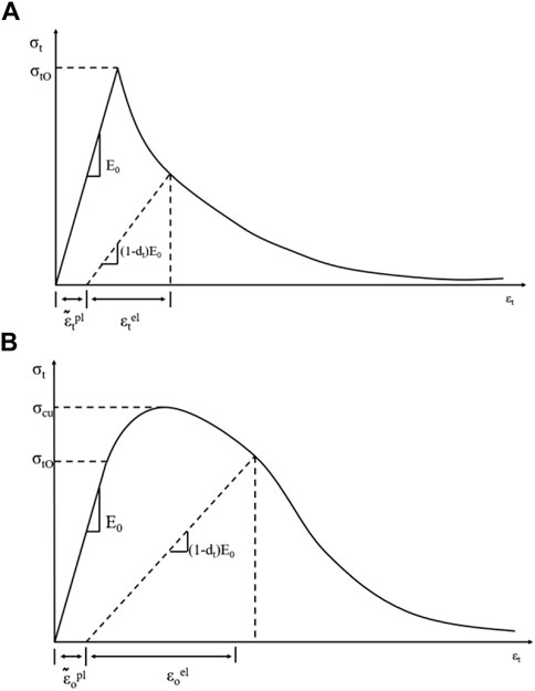
FIGURE 1. Tension and compression curves of concrete. (A) Concrete in CDP model tensile cracking strain; (B) Concrete in CDP model compression cracking strain.
The stress-strain relationship between tension and compression can be expressed as follows:
where the subscripts
The model assumes that the reduction of the elastic modulus is given by the scalar degenerate variable.
where
where
It is defined as follows:
where
Damage factor calculation
Concrete has a large difference between compression and tension properties due to its inherent properties (Lubliner et al., 1989), so the damage factor
Bringing in
Among them,
Similarly, we can obtain
Among them,
By defining an effective constitutive parameter model (Labibzadeh et al., 2017), we can obtain
Model building and parameter selection
The Jinping II Hydropower Station tunnel adopts the drill and blast construction method, and the lining is a composite lining with initial spray anchor support and secondary mold column support. As the calculation process mainly considers large deformation strong nonlinear analysis, in order to calculate smoothly, the lining is simplified to one layer with a thickness of 0.6 m. The model section size is selected as 100 m × 100 m. The width of the fracture zone is 40 m. In order to simulate the actual situation as much as possible, the fracture surface is set in the fault, as shown in Figure 2, and the simulation is carried out by setting the friction factor of the contact surface. The friction factor in the contact surface was selected as 0.75 (Cheng et al., 2019), and 200 m of the upper and lower sides of the model were selected for research. The model situation and the location of each section are shown in Figure 3.
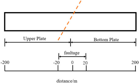
FIGURE 2. Schematic diagram of tunnel and fault location.
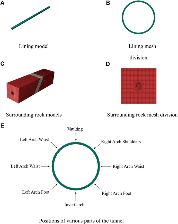
FIGURE 3. Modeling model of tunnel surrounding rock. (A) FEM Lining model; (B) FEM Lining mesh; (C) Surrounding rock models; (D) Surrounding rock mesh division.
With reference to the actual exploration engineering data (Wu and Wang, 2011) and combined with the specification requirements, the physical and mechanical parameters of the surrounding rock (marble) and fault and the concrete parameters (C30) of the lining are given in Tables 1 and 2. The CDP (concrete damaged plasticity model) (Lubliner et al., 1989; George et al., 2017) is used for the lining, the elastic-plastic material is used for the surrounding rock and fracture zone (Wang et al., 2022), and the damage criterion used is Mohr–Coulomb’s law (Bahmani et al., 2019).
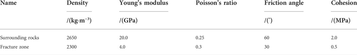
TABLE 1. Material parameters used in simulation.
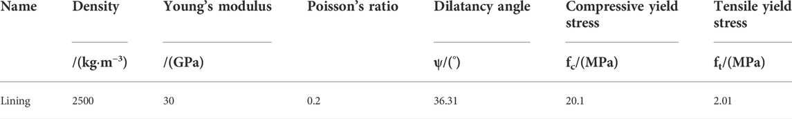
TABLE 2. Lining material parameters used in simulation.
In order to calculate the damage response of the tunnel under fault dislocations, a FEM model based on a quasi-static elastoplastic constitutive model is constructed. It is used to calculate the nonlinear damage evolution of the tunnel due to large displacement caused by fault dislocation.
Numerical simulations were carried out using ABAQUS software, and the simulation modeling used the same dimensions as the original ones. The simulation was carried out in three steps: 1) gravity loading was applied to the surrounding rock of the original data, and the ground stress was balanced; 2) the rock excavation was simulated, and the tunnel lining was added; 3) the forced displacement of the upper and lower plates was applied to simulate the fault dislocation. Four working conditions were set, and the amount of dislocation was dislocation 1, 2.5, 5, and 10 cm, respectively. The forced displacement of the corresponding working conditions is applied to the upper and lower plates. The applied displacement is to apply the corresponding displacement along the dislocation direction. Each working condition is individually loaded.
Results and discussion
Analysis of positive fault dislocation
In order to explain the stress of the maximum and minimum principal stress under the damage constitutive of this paper, the elastic model is specially established. In the elastic model, the maximum minimum principal stresses for the four working conditions follow the same trend, as shown in Figure 4. As the amount of dislocation increases, the maximum and minimum principal stress increases accordingly. The maximum and minimum principal stress values in each part of the tunnel increase proportionally with the increase in dislocation. Near the fault plane, the internal force distribution on both sides of the dislocation plane increases sharply, and the influence of the fault on the tunnel is concentrated and strong. The maximum and minimum principal stress peaks appear at the arch waist and gradually extend to the vault and invert arch. The damage pattern is the same as that shown in Figure 6.
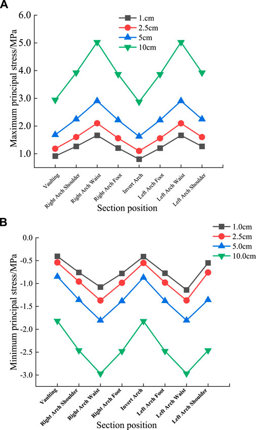
FIGURE 4. Distribution diagram of maximum and minimum principal stresses under elastic constitutive conditions. (A) Elastic model lining section maximum principal stress; (B) Elastic model lining section Minimum principal stress.
In the elastoplastic damage model, as shown in Figure 5, the stress characteristics tend to become more complex as the damage occurs. As the damage at the top of the arch is still relatively small, the stresses at the site still increase with the amount of dislocation. However, the damage at the arch waist is more serious, and the stress decreases with the increase of damage. This is in accordance with the laws of concrete mechanical properties. The damage occurs mainly in the form of tensile damage.
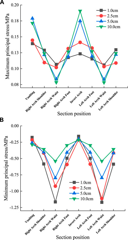
FIGURE 5. Maximum and minimum principal stress distribution under plasticity principal structure. (A) Elastic-plastic tunnel section maximum principal stress; (B) Elastic-plastic tunnel section minimum principal stress.
As can be seen from Figure 5, the maximum increase in the maximum principal stress at the top of the arch after the dislocation is 1.23 times, and the maximum increase in the maximum principal stress at the arch shoulder is 1.36 times. The maximum increase in the minimum principal stress at the top of the arch is 1.62 times, and the maximum increase in the minimum principal stress at the arch foot is 1.83 times. The maximum increase of the minimum principal stress at the arch waist is 2.16 times, which shows that the dislocation distance of the positive fault has a greater influence on the section stress, and the influence on the arch waist is greater than that on the arch foot and arch shoulder.
The DAMAGEC at the axial lift interface along the tunnel is extracted, and the DAMAGEC at the arch waist and the invert arch is extracted. The values are shown in Figure 6.
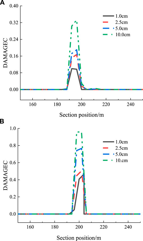
FIGURE 6. Compression damage under positive fault. (A) Tunnel cross-section DMAMAGEC at the invert arch; (B) Tunnel cross-section DAMAGEC at the arch waist.
As shown in Figure 6 and Figure 7, in the positive fault action under the four dislocation works trend is basically the same, not affected by the amount of dislocation. The damage increased with the increase of dislocation and reached the peak at 5 m from the dislocation surface; the DAMAGEC at the arch waist was significantly larger than that at the supine arch. The arch waist was the most unfavorable section; the damage extended from the arch waist to the vault and the invert arch. The influence range of dislocation has a slight increase with the increase of dislocation.
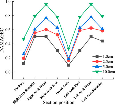
FIGURE 7. Damage parameters of various parts of positive fault section.
The damage value of the upper and lower plates reached the peak at about 5 m from the dislocation surface. However, it rapidly dropped 10 m away from the fracture surface, and the main impact area of the fracture surface was more concentrated. Within 10 m of each of the upper and lower plates on the fracture surface, the increase in dislocation tunnel damage range is not obvious, mainly reflected in the change in the peak value of the damage.
Analysis of inverse fault dislocation
For the four working conditions of the dislocation analysis of the reverse fault, the DAMAGEC of the section at the arch foot and the arch waist along the tunnel axis is extracted, as shown in Figure 8.
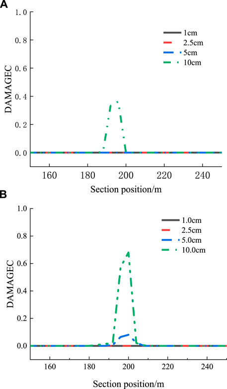
FIGURE 8. Damage evolution under reverse fault. (A) Tunnel cross-section DAMAGEC at the foot of the arch (B) Tunnel cross-section DAMAGEC at the arch waist.
From Figure 8 and Figure 9, it can be seen that the change trend under the four dislocation conditions is basically the same and is not affected by the amount of dislocation. The damage increases with the amount of dislocation, and the damage at the arch waist under each working condition is the largest and the most unfavorable section. Compared with the positive fault, the reverse fault is mainly damaged by compression (Ghadimi Chermahini and Tahghighi, 2019), so the peak value of DAMAGEC at the same position under the same dislocation is obviously smaller than that of the positive fault. The dislocation face affects the tunnel for about 20 m, and its affected area is larger than the positive fault.
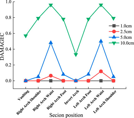
FIGURE 9. Damage parameters of various parts of reverse fault cross-section.
Therefore, the reverse fault is close to the positive fault in the form of a damage extension pattern, both from the waist arch to the vault and the invert of the arch. But the damage value is significantly lower than the positive fault under the same amount of dislocation.
The dislocation surface affects the front and rear of the tunnel for about 20 m, and its affected area is larger than that of the positive fault.
The damage to the tunnel reached a peak at about 8 m from the fracture surface and then declined rapidly. The damage occurred mainly in the form of compression damage.
Analysis of strike-slip fault dislocation
The dislocation analysis of the strike-slip fault is divided into four working conditions, and the DAMAGEC of the arch waist arch top sections along the tunnel axis is extracted, as shown in Figure 10.
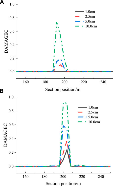
FIGURE 10. Damage evolution of strike-slip faults. (A) Tunnel cross-section DAMAGEC at the arch waist; (B) Tunnel cross-section DAMAGEC at the arch vault.
From Figure 10 and Figure 11, it can be seen that the trend is basically the same under the four dislocation conditions, which are not affected by the amount of misalignment. Under the action of strike-slip fault, The damage increases with the amount of dislocation.
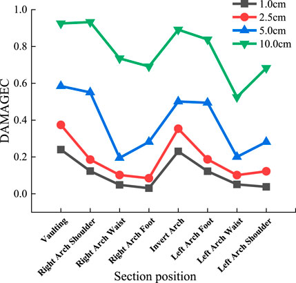
FIGURE 11. Damage parameters of each part of the section.
The strike-slip fault damage pattern is opposite to that of the positive fault and reverse fault. Under each working condition, the DAMAGEC at the vault and invert arch of the tunnel is relatively large, while the damage at the waist arch of the tunnel is relatively small. The damage extends from the vault and invert arch to the waist arch. The damage pattern is different from that of positive and inverse faults. The reason is that the strike-slip fault mainly suffers from transverse shear failure (Karamitros et al., 2007).
The affected area before and after the fault is about 15 m before and after the dislocation surface. The damage to the tunnel reached the peak at 8–10 m from the fracture surface and then decreased rapidly. The structure underwent damage mainly in the form of shear failure.
Tunnel lining response analysis
Tunnel lining response analysis was performed by comparing the response of three different fault dislocation form tunnels, as shown in Table 3 and Figure 12. Due to the influence of fault damage form, by the way the fault is affected by tensile stress is dominant, the maximum stress and damage appeared in the positive fault. The next is strike slip fault, the damage form is shear damage, and the maximum value of damage and stress is between positive fault and reverse fault. Since the reverse fault is mainly damaged by compression, the stress and damage is minimal.
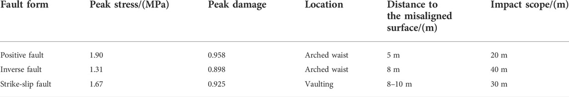
TABLE 3. Tunnel parameters under different fault dislocation conditions.
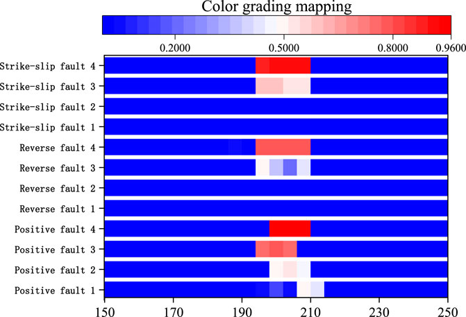
FIGURE 12. Damage proportion under various working conditions.
In the CDP model described earlier, the damage indicator is generally characterized by, which takes a value between 0 and 1. When
From Figure 12, it can be obtained that the degree of damage of different fault forms varies significantly under the same amount of dislocation. The damage of positive fault is the largest and most concentrated. The reverse fault has the smallest damage value but the widest damage range. The damage peak value and damage range of strike-slip fault are between normal fault and reverse fault. The maximum influence range of positive fault damage value is the smallest. The damage peak value is inversely proportional to the damage range. The reasons are as follows: 1) The tensile fracture energy of concrete is far less than the compressive property. 2) The concrete material loses its tensile property after the tensile damage reaches the limit, while the compression will continue to bear the pressure after the damage, thus, further expanding the damage range. Therefore, under the same amount of dislocation, the damage peak value and damage growth range present the opposite regulation.
Conclusion
In this article, the influence of different fault dislocations on tunnel damage in Jinping II Hydropower Station was simulated by FEM. A three-dimensional numerical analysis model of the tunnel-rock-fault zone was established to discuss the influence of two factors, fault dislocation form and the amounts, on the tunnel damage distribution. The following conclusions were drawn as follows:
1) The influence of the fault dislocation on the tunnel is more concentrated and intense, and the distribution of internal forces increases sharply on both sides of the dislocation surface. The distribution of the maximum minimum principal stress is affected by the size of the fault dislocation. The maximum minimum principal stress increases monotonically with the amount of dislocation in the elastic and damage initial stage; when the damage begins to the damage limit of the process, the structure can withstand the maximum minimum principal stress extreme value will be reduced.
2) In the model used in this paper, the scope of tunnel damage is less affected by the amount of dislocation momentum and more affected by the form of dislocation.
3) Under the action of strike-slip fault, the most unfavorable section is at the vault and invert of the tunnel. Under the action of the positive fault and reverse fault, the arch waist is the most unfavorable section. The amount of damage to positive faults is greater than that to strike-slip faults than to reverse faults. It can be inferred that the most unfavorable section is on both sides perpendicular to the fault dislocation direction. This damage distribution rule can provide a reference for the seismic design and construction of tunnels through faults.
4) There is a large quantity of joints and discontinuous media in the actual inter-engineering rock, and irregular changes will occur with the dislocation distance. Thus, the physical properties and damage distribution of real faults need to be further considered and explored in the future.
Data availability statement
The original contributions presented in the study are included in the article/Supplementary Material; further inquiries can be directed to the corresponding author.
Author contributions
YC: conceptualization, methodology, software, formal analysis, investigation, resources, writing—original draft preparation, and visualization. JW: methodology, resources, writing—review and editing, visualization, supervision, project administration, and funding acquisition. SZ: supervision and revision. ST: editing and revision. All authors have read and agreed to the published version of the manuscript.
Funding
This research was funded by the National Natural Science Foundation of China (U196520006 and 41807277) and the Natural Science Foundation of Hebei Province (D2019202440).
Conflict of interest
Author SZ was employed by the Company of Guangzhou Municipal Engineering Design and Research Institute.
The remaining authors declare that the research was conducted in the absence of any commercial or financial relationships that could be construed as a potential conflict of interest.
Publisher’s note
All claims expressed in this article are solely those of the authors and do not necessarily represent those of their affiliated organizations, or those of the publisher, the editors, and the reviewers. Any product that may be evaluated in this article, or claim that may be made by its manufacturer, is not guaranteed or endorsed by the publisher.
References
Alembagheri, M., and Ghaemian, M. (2013). Damage assessment of a concrete arch dam through nonlinear incremental dynamic analysis. Soil Dyn. Earthq. Eng. 44, 127–137. doi:10.1016/j.soildyn.2012.09.010
Amirpour, A., and Mirzabozorg, H. (2014). Quantifying the qualitative limit-states using IDA approach in concrete arch dams. Arab. J. Sci. Eng. 39 (11), 7729–7740. doi:10.1007/s13369-014-1393-z
Archuleta, R. J. (1984). A faulting model for the 1979 Imperial Valley earthquake. J. Geophys. Res. 89 (B6), 4559–4585. doi:10.1029/jb089ib06p04559
Bahmani, B., Abedi, R., and Clarke, P. L. (2019). A stochastic bulk damage model based on mohr-coulomb failure criterion for dynamic rock fracture. Appl. Sci. 9 (5), 830. doi:10.3390/app9050830
Bai, B., Wang, Y., Rao, D., and Bai, F. (2022). The effective thermal conductivity of unsaturated porous media deduced by pore-scale SPH simulation. Front. Earth Sci. (Lausanne). 10, 943853. doi:10.3389/feart.2022.943853
Bai, B., Yang, G. C., Li, T., and Yang, G. S. (2019). A thermodynamic constitutive model with temperature effect based on particle rearrangement for geomaterials. Mech. Mater. 139, 103180. doi:10.1016/j.mechmat.2019.103180
Bai, B., Zhou, R., Cai, G., Hu, W., and Yang, G. (2021). Coupled thermo-hydro-mechanical mechanism in view of the soil particle rearrangement of granular thermodynamics. Comput. Geotechnics 137, 104272. doi:10.1016/j.compgeo.2021.104272
Baziar, M. H., Nabizadeh, A., Lee, C. J., and Hung, W. Y. (2014). Centrifuge modeling of interaction between reverse faulting and tunnel. Soil Dyn. Earthq. Eng. 65, 151–164. doi:10.1016/j.soildyn.2014.04.008
Cai, Q., Peng, J., Ng, C. W., Shi, J., and Chen, X. (2019). Centrifuge and numerical modelling of tunnel intersected by normal fault rupture in sand. Comput. Geotechnics 111, 137–146. doi:10.1016/j.compgeo.2019.03.010
Cao, Y., Zhang, J., Xu, G., Li, M., and Bian, X. (2022). Strength properties and prediction model of cement-solidified clay considering organic matter and curing temperature. Front. Mat. 9, 965975. doi:10.3389/fmats.2022.965975
Chang, Y., Lee, C., Huang, W., Hung, W., Huang, W., Lin, M., et al. (2015). Evolution of the surface deformation profile and subsurface distortion zone during reverse faulting through overburden sand. Eng. Geol. 184, 52–70. doi:10.1016/j.enggeo.2014.10.023
Chen, Z., Shi, C., Li, T., and Yuan, Y. (2012). Damage characteristics and influence factors of mountain tunnels under strong earthquakes. Nat. Hazards (Dordr). 61 (2), 387–401. doi:10.1007/s11069-011-9924-3
Cheng, X., Ma, C., Huang, R., Huang, S., and Yang, W. (2019). Failure mode analysis of X80 buried steel pipeline under oblique-reverse fault. Soil Dyn. Earthq. Eng. 125, 105723. doi:10.1016/j.soildyn.2019.105723
George, J., Rama, J. K., Kumar, M. S., and Vasan, A. (2017). Behavior of plain concrete beam subjected to three point bending using concrete damaged plasticity (CDP) model. Mater. Today Proc. 4 (9), 9742–9746. doi:10.1016/j.matpr.2017.06.259
Ghadimi Chermahini, A., and Tahghighi, H. (2019). Numerical finite element analysis of underground tunnel crossing an active reverse fault: A case study on the sabzkouh segmental tunnel. Geomechanics Geoengin. 14 (3), 155–166. doi:10.1080/17486025.2019.1573323
Hebbouche, A., Bensaibi, M., Mroueh, H., and Bensalah, M. D. (2020). Seismic fragility curves and damage probabilities of concrete gravity dam under near–far faults ground motions. Struct. Eng. Int. 30 (1), 74–85. doi:10.1080/10168664.2018.1531686
Ismail, M., and Casas, J. R. (2016). Evaluation and refinement of closely spaced buildings’ performance under near-fault ground motions. Struct. Infrastructure Eng. 12 (1), 21–44. doi:10.1080/15732479.2014.993660
Jalali, H. H., Rofooei, F. R., Attari, N., and Samadian, M. (2016). Experimental and finite element study of the reverse faulting effects on buried continuous steel gas pipelines. Soil Dyn. Earthq. Eng. 86, 1–14. doi:10.1016/j.soildyn.2016.04.006
Karamitros, D. K., Bouckovalas, G. D., and Kouretzis, G. P. (2007). Stress analysis of buried steel pipelines at strike-slip fault crossings. Soil Dyn. Earthq. Eng. 27 (3), 200–211. doi:10.1016/j.soildyn.2006.08.001
Kelson, K. I., Kang, K.-H., Page, W. D., Lee, C.-T., and Cluff, L. S. (2001). Representative styles of deformation along the chelungpu fault from the 1999 chi-chi (taiwan) earthquake: Geomorphic characteristics and responses of man-made structures. Bull. Seismol. Soc. Am. 91 (5), 930–952. doi:10.1785/0120000741
Kiani, M., Akhlaghi, T., and Ghalandarzadeh, A. (2016). Experimental modeling of segmental shallow tunnels in alluvial affected by normal faults. Tunn. Undergr. Space Technol. 51, 108–119. doi:10.1016/j.tust.2015.10.005
Kieffer, D. S., Caulfield, R. J., and Cain, W. (2001). “Seismic upgrade of the claremont tunnel, northern California,” in 2001 proceedings/rapid excavation and tunneling conference: SME) (San Diego, Calif., USA: Rapid Excavation and Tunneling Conference).
Labibzadeh, M., Zakeri, M., and Shoaib, A. A. (2017). A new method for CDP input parameter identification of the ABAQUS software guaranteeing uniqueness and precision. Int. J. Struct. Integr. 8 (2), 264–284. doi:10.1108/ijsi-03-2016-0010
Liu, X., Li, X., Sang, Y., and Lin, L. (2015). Experimental study on normal fault rupture propagation in loose strata and its impact on mountain tunnels. Tunn. Undergr. Space Technol. 49, 417–425. doi:10.1016/j.tust.2015.05.010
Livaoglu, H., Irmak, T. S., and Gueven, I. T. (2019). Seismic vulnerability indices of ground for degirmendere (Kocaeli Province, Turkey). Bull. Eng. Geol. Environ. 78 (1), 507–517. doi:10.1007/s10064-017-1102-8
Lubliner, J., Oliver, J., Oller, S., and O?Ate, E. (1989). A plastic-damage model for concrete. Int. J. Solids Struct. 25 (3), 299–326. doi:10.1016/0020-7683(89)90050-4
Ma, K. F., Lee, C. T., Tsai, Y. B., Shin, T. C., and Mori, J. (1999). The Chi-Chi, Taiwan earthquake: Large surface displacements on an inland thrust fault. Eos Trans. AGU. 80 (50), 605–611. doi:10.1029/99EO00405
Ma, S., Zhang, L., Wang, D., Tan, X. R., Li, S., and Liu, Y. (2021). Analysis of tunnel lining failure mechanism under the action of active fault. Shock Vib. 2021, 1–11. doi:10.1155/2021/9918021
Ma, Y., Sheng, Q., Zhang, G., and Cui, Z. (2019). A 3D discrete-continuum coupling approach for investigating the deformation and failure mechanism of tunnels across an active fault: A case study of xianglushan tunnel. Appl. Sci. 9 (11), 2318. doi:10.3390/app9112318
Marchandon, M., Hollingsworth, J., and Radiguet, M. (2020). Origin of the shallow slip deficit on a strike-slip fault: Influence of elastic structure, topography, data coverage, and noise. Earth Planet. Sci. Lett. 554, 116696. doi:10.1016/j.epsl.2020.116696
Peng, J. B., Chen, L. W., Huang, Q. B., Men, Y. M., Fan, W., and Yan, J. K. (2013). Physical simulation of ground fissures triggered by underground fault activity. Eng. Geol. 155, 19–30. doi:10.1016/j.enggeo.2013.01.001
Peng, J. B., Huang, Q. B., Hu, Z. P., Wang, M. X., Li, T., Men, Y. M., et al. (2017). A proposed solution to the ground fissure encountered in urban metro construction in Xi'an, China. Tunn. Undergr. Space Technol. 61, 12–25. doi:10.1016/j.tust.2016.09.002
Rajyaswori, S., Li, X., Luo, Y., Kumar, M. A., and Xu, K. (2020). The effect of overburden depth on the damage of underground structure during earthquake. IOP Conf. Ser. Earth Environ. Sci. 455, 012067. doi:10.1088/1755-1315/455/1/012067
Rofooei, F. R., Attari, N., and Jalali, H. H. (2018). New method of modeling the behavior of buried steel distribution pipes subjected to reverse faulting. J. Pipeline Syst. Eng. Pract. 9 (1), 04017029–04017021. doi:10.1061/(ASCE)PS.1949-1204.0000296
Russo, M., Germani, G., and Amberg, W. (2002). “Design and construction of large tunnel through active faults: A recent application,” in Proceedings international conference of tunneling and underground space use (Istanbul: Turkey: Prague, Czech Republic), 1–14.
Sabagh, M., and Ghalandarzadeh, A. (2020). Centrifugal modeling of continuous shallow tunnels at active normal faults intersection. Transp. Geotech. 22, 100325. doi:10.1016/j.trgeo.2020.100325
Wang, J., Sun, K., Hu, Y., Guan, Q., and Li, Q. (2022). The mechanical properties of concrete in water environment: A review. Front. Mat. 9, 996650. doi:10.3389/fmats.2022.996650
Wu, S., and Wang, G. (2011). Rock mechanical problems and optimization for the long and deep diversion tunnels at Jinping II hydropower station. J. Rock Mech. Geotechnical Eng. 3 (4), 314–328. doi:10.3724/SP.J.1235.2011.00314
Xuepeng, Z., Zhang, Y., Jiang, K., and Maegawa, W. (2020). Mountain tunnel under earthquake force:A review of possible causes of damages and restoration methods. J. Rock Mech. Geotechnical Eng. 12 (02), 414–426. doi:10.1016/j.jrmge.2019.11.002
Yagi, Y., and Kikuchi, M. (2000). Source rupture process of the Kocaeli, Turkey, earthquake of August 17, 1999, obtained by joint inversion of near‐field data and teleseismic data. Geophys. Res. Lett. 27 (13), 1969–1972. doi:10.1029/1999GL011208
Yan, G., Shen, Y., Gao, B., Zheng, Q., Fan, K., and Huang, H. (2020). Damage evolution of tunnel lining with steel reinforced rubber joints under normal faulting: An experimental and numerical investigation. Tunn. Undergr. Space Technol. 97, 103223. doi:10.1016/j.tust.2019.103223
Yi, S., Liu, J., and Gu, M. (2022). Field investigation of steel pipe pile under lateral loading in extensively soft soil. Front. Mat. 480, 97148. doi:10.3389/fmats.2022.971485
Yp, A., Li, C. A., and Jian, Z. B. (2020). Seismic performance evaluation of fiber-reinforced concrete bridges under near-fault and far-field ground motions. Structures 28, 1366–1383. doi:10.1016/j.istruc.2020.09.049
Zaheri, M., Ranjbarnia, M., Dias, D., and Oreste, P. (2020). Performance of segmental and shotcrete linings in shallow tunnels crossing a transverse strike-slip faulting. Transp. Geotech. 23, 100333. doi:10.1016/j.trgeo.2020.100333
Zhao, K., Chen, W., Yang, D., Zhao, W., Wang, S., and Song, W. (2019). Mechanical tests and engineering applicability of fibre plastic concrete used in tunnel design in active fault zones. Tunn. Undergr. Space Technol. 88, 200–208. doi:10.1016/j.tust.2019.03.009
Keywords: Jinping II Hydropower Station, fault movement, Rule of damage evolution, FEM, rupture form
Citation: Chen Y, Wu J, Zhang S and Teng S (2022) Influence of fault forms on the evolution of concrete damage patterns in tunnels. Front. Mater. 9:1037771. doi: 10.3389/fmats.2022.1037771
Received: 06 September 2022; Accepted: 20 September 2022;
Published: 19 October 2022.
Edited by:
Xianze Cui, China Three Gorges University, ChinaReviewed by:
Shibing Huang, Wuhan University of Science and Technology, ChinaQing Ai, Shanghai Jiao Tong University, China
Copyright © 2022 Chen, Wu, Zhang and Teng. This is an open-access article distributed under the terms of the Creative Commons Attribution License (CC BY). The use, distribution or reproduction in other forums is permitted, provided the original author(s) and the copyright owner(s) are credited and that the original publication in this journal is cited, in accordance with accepted academic practice. No use, distribution or reproduction is permitted which does not comply with these terms.
*Correspondence: Jie Wu, amllLnZvb0BnbWFpbC5jb20=