- 1State Key Laboratory for Strength and Vibration of Mechanical Structures, School of Aerospace, Xi’an Jiaotong University, Xi’an, China
- 2Science and Technology on Reactor System Design Technology Laboratory, Nuclear Power Institute of China, Chengdu, China
The material cracking behavior in the reactor is generated under the irradiation effect accompanied by thermal expansion, fission product diffusion, and mechanical load. In this study, the energy release rate for crack growth under irradiation has been deduced synthetically according to the thermodynamically consistent method and numerically implemented by the finite element method (FEM). Variation in the total energy was obtained based on the principle of minimum potential energy in which the dissipative behavior can be characterized by fission energy, irreversible heat flow, and diffusion of fission products. Through calculating the variation in the total energy with respect to crack length, the energy release rate for crack propagation was analytically represented. Additionally, the total energy release rate for deflective cracks was also derived to predict the crack kinking. Furthermore, the numerical implementation of the presented model was performed by FEM and the equivalent domain integral method. Effects of irradiation on the physical fields and the energy release rate near the crack tip were investigated and analyzed in such a complex I-TDM coupling system. This study can be developed to investigate fracture problems, assess structural integrity, and evaluate material strength of irradiated materials.
Introduction
Cracks within the fuel elements and the structural components in reactors are produced and propagated due to the irradiation behaviors (Bai et al., 2010; Jeong et al., 2015; Liu et al., 2018) including thermal expansion, diffusion of fission products (Hall et al., 2016; Kim et al., 2016), and mechanical deformation. Thus, material cracking under irradiation is an irradiation-induced thermo-diffusion-mechanical (abbreviated as I-TDM in this article) coupling behavior. However, in such a typical I-TDM coupling system, the energy release rate at the crack tip has not been explicitly represented due to the complexity. In order to evaluate and optimize the safety of irradiated materials, it is desirable to investigate the cracking behavior and determine the fracture criterion for materials under irradiation.
Generally, the cracking of irradiated materials is induced by fission reactions and neutron irradiation. The neutron-induced nuclear chain reaction will generate tremendous amounts of thermal energy and extensive fission products (Nordlund et al., 2018), which will result in the irradiation effect on surrounding structural materials. The energy released by the fission reaction is dissipated for irreversible mechanical strain, amounts of heat flow, diffusion of fission products, and forming the new surfaces of cracks. Hence, the irradiated materials should be regarded as an irradiation-induced thermo-diffusion-mechanical coupling system in which the cracking behavior is distinctive due to the irradiation effect (Suzuki and Kobayashi, 2008; Suo and Shen, 2012; Hu and Shen, 2013; Bouklas et al., 2015; Granberg et al., 2016; Noori-kalkhoran and Gei, 2020). The fission energy, the thermal potential energy, and the mechanical energy are utilized as the driving force for crack growth in irradiated materials. However, little research has been reported to analytically investigate the crack growth in the typical I-TDM coupling system.
Through characterization of the energy dissipation due to unit crack growth (Kuroda et al., 2001; Samala et al., 2010; Gao and Zhou, 2013; Cai and Guo, 2020), the energy release rate in fracture mechanics represents the driving force for crack growth and can be utilized to evaluate the fracture behaviors (Cherepanov, 1967; Rice, 1968; Zuo and Chen, 2018). The representation of the energy release rate near the crack tip in irradiated materials has not been explicitly established. Variation in the total energy in multiple field coupling systems can be formulated by several approaches, such as the non-equilibrium thermodynamic approach (Ricoeur and Kuna, 2008), the Onsager principle of the least energy dissipation (Nikolaevskij, 1982), Noether’s theorem (Yu, 2018), and the material configuration forces (Li and Kuna, 2012). Among them, the non-equilibrium thermodynamic approach possesses the advantage of characterizing the irreversible processes under irradiation and has been adopted in this study. Compared with the unirradiated materials, in which only mechanical energy is employed as the driving force for crack growth, the crack propagation, the heat flow, and the fission product diffusion dissipate energies simultaneously in irradiated materials. The cracking behavior under irradiation is driven by the accumulation of the mechanical strain energy, the thermal potential energy, and the diffusion potential energy. Thus, the effects of the temperature and the diffusion of fission products must be taken into account to determine the total energy release rate of crack growth under irradiation.
Overall, based on the thermodynamically consistent method and the principle of minimum potential energy, variation in the total energy and the constitutive relationship can be formulated in irradiated materials. By partial differential of the total energy, the energy release rates for the crack growth and the crack kinking can be derived and are denoted as the path-independent J-integral. Then, the energy release rate can be numerically implemented by the finite element method (FEM) and analyzed under different irradiation conditions. The effect of the irradiation damage (dpa) on the energy release rate and the stress state near the crack tip can be solved with the aid of the proposed governing equations.
The main aim of this study is to characterize the energy release rate in the I-TDM coupling system and numerically implement the presented model by FEM. The internal energy density in the I-TDM coupling system was determined based on the thermodynamically consistent method. Under irradiation, variations in the total energy and the constitutive relationship were determined with the aid of the principle of minimum potential energy. The energy release rate for crack growth was derived systematically and is denoted as the J-integral in irradiated materials. Furthermore, the total energy release rate accounting for the deflective crack in the I-TDM coupling system was formulated. The presented model was numerically implemented by FEM based on the equivalent domain integral method. Then, a crack model was simulated and investigated under irradiation. The physical fields and the J-integral near the crack tip were numerically solved and analyzed. This study lays a foundation for analyzing the irradiation-dependent fracture problems and improving the safety of irradiated materials.
The thermodynamic approach in the I-TDM coupling system
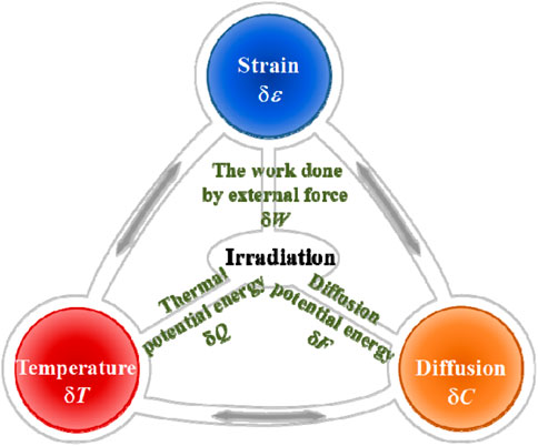
Under irradiation, the cracking occurs in a typical I-TDM coupling system, as shown in Figure 1. Fission heat and fission products are generated in nuclear fuels and diffused in irradiated materials. The thermal expansion by high temperature and the swelling by fission products will induce the mechanical deformation and the cracking behaviors under irradiation. Variations in temperature
In the I-TDM coupling system, as depicted in Figure 1, according to the universal thermodynamic variational principle (Suo and Shen, 2012), variations in all energies satisfy
where
According to the first law of thermodynamics, within a chosen region V surrounded by surface A, there exists
where the spot overhead the letters denotes differentiating with respect to time. The balance between the total energy in the local region V and the energy flowing through the closed surface A is governed by the expression in Eq. 3 (Ricoeur and Kuna, 2008).
Generally, the variation rate of the total internal energy in Eq. 3 is depicted taking the form of
where
The variation rate of the work performed by external force should be expressed as
where
Trough applying the equivalent equation and the geometric relation into Eq. 5, the variation rate of the work performed by the external force in Eq. 5 can be modified by the Gauss theorem as
Where
The thermal potential energy is equal to the sum of the heat generated by fission and the heat flow through the surface A, i.e.,
where
Then, on the basis of the expression of the entropy flow vector, the variation rate of the thermal potential energy in Eq. 7 can be rewritten as
Moreover, the diffusion potential energy of fission products is the sum of the fission product potential and the diffusion flow through surface A, i.e.,
where
Then, the variation rate of the diffusion potential energy in Eq. 9 is presented taking the following form:
By substituting Eqs. 6, 8, and 10 into Eq. 3, the variation rate of the total internal energy is expanded as
The mechanical field and the thermal field are coupled by the thermal strain (Liu et al., 2009), while the diffusion field induced by the fission products will produce the diffusion strain (Wang et al., 2011). Let
where
The heat flow is driven by the temperature gradient, while the diffusion potential flow is driven by the diffusion gradient of fission products. According to Eqs. 12–13, the temperature gradient and the concentration gradient of fission products are developed as
The temperature gradient and the concentration gradient of fission products are correlated and can be characterized by the Soret effect and the Dufour effect (Suo and Shen, 2012). For brevity, this study will assume a linearly coupled thermal-diffusion system. Taking into account the thermo-diffusion coupling coefficient
Furthermore, by substituting Eq. 4 into Eq. 16, there exists
Due to the mechanical relationship
where
The energy released by the fission reaction includes the thermal potential energy and the diffusion potential energy, namely,
For the non-fuel phase and the structural components in reactors, the energy released by fission pF is zero, and the internal energy density is composed by the mechanical part, the thermal part, and the diffusion part induced by irradiation.
According to the non-equilibrium thermodynamics method, there exists conservation of the total energy throughout the transient stage (Nikolaos et al., 2015). Therefore, variation in the total energy must vanish at any time. According to Eqs. 4, 5, 7, and 9, by substituting variations of the total internal energy, the work performed by the external force, the thermal potential energy, and the diffusion potential energy into Eq. 2, variation in the total energy is formulated based on the principle of minimum potential energy as
where
By substituting Eq. 18 into Eq. 20 and applying the chain rule of differentiation and Gauss divergence theorem, the variation in the total energy in the I-TDM coupling system is modified as
Furthermore, according to the relationship between the fission energy, the thermal potential energy, and the diffusion potential energy, variation in the fission energy can be represented as
where
In Eq. 21, to minimize variation in the total energy in the I-TDM coupling system, for arbitrary
Also, the boundary conditions on surface A are obtained as
Let
where
The energy release rate for crack growth in the I-TDM coupling system
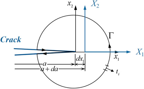
In fracture mechanics, the driving force of crack growth is the variation in the total energy near the crack tip. The total energy release rate is determined as a function of crack propagation (Guo and Li, 2017). In an I-TDM coupling system, the energy associated with temperature and fission product diffusion must be accounted for to construct the energy balance in a closed contour around the crack tip. For a two-dimensional crack in an I-TDM coupling system as presented in Figure 2, the crack length is denoted as
It is assumed that
In view of transformation relationships in Eqs 27, 28, the variation rate of the total energy with respect to the crack length in Eq. 26 is rewritten as
According to the boundary conditions in Eq. 24 and the constitutive relationship in Eq. 25, the partial derivative terms of crack length in Eq. 29 can be eliminated. Thus, the variation rate of the total energy with respect to the crack length in Eq. 29 can be modified as
Generally, the energy release rate
Furthermore, according to the Green’s function, the surface integral in Eq. 30 can be transformed into a line integral. After arrangements, the J-integral and the energy release rate
It is observed in Eq. 32 that the energy release rate near the crack tip is equivalent to the difference between the energy stored in the integral path and the energy dissipated through the integral path, that is, the surface energy required for forming new cracks. Within the closed integral contour near the crack tip, the energy released by fission has been dissipated for the thermal flow, the fission product diffusion, the irreversible strain, and the crack growth. As the driving force for crack growth, the energy release rate at the crack tip is a non-equilibrium characterization of total energy in the I-TDM coupling system. For structural materials, the fission energy density
Under irradiation, the energy release rate synthetically characterizes variations in the fission energy, the strain energy, the heat flow, and the diffusion of fission products near the crack tip. Also, the initiation of crack propagation can be predicted according to the proposed criterion. As the energy criterion for crack growth, the presented model can be utilized to assess structural integrity and evaluate the strength of irradiated materials. Actually, by ignoring variables associated with the fission reaction, including the fission energy
It is known that the conventional J-integral is path-independent (Zuo and Shen, 2018). Next, the path-independence of J-integral in the I-TDM coupling system will be investigated. Under irradiation, taking into account the closed integral path
where Γ1 and Γ2 stand for two distinct integral paths from the lower crack surface to the upper crack surface, while Γ3 and Γ4 denote the paths along the lower and upper crack surfaces, respectively.
According to the relation between any arc length on the integral path and normal vector, there exists
It is assumed that temperature, concentration of fission products, and crack opening displacement are free on the crack surfaces Γ3 and Γ4, and the contributions of
By substituting Eq. 34 into Eq. 32 and employing the Gauss–Green’s theorem to a closed contour Γ, the J-integral is expanded as follows:
where ΓA denotes the integral domain corresponding to the integral path
It is identified that Eq. 36 can be divided into two terms for convenience. For term I, applying the equilibrium equations in Eq. 23, there exists
Through employing the Gauss–Green’s theorem, term II can be expanded as
By substituting Eqs. (37)–(38) into Eq. 36, it is identified that
Hence, the values of the J-integral along different integral contours near the crack tip are equal. In the I-TDM coupling system, the J-integral in Eq. 32 is validated to be path-independent.
The energy release rate with respect to deflective cracks
Under irradiation, due to coupling behaviors of the non-symmetric material structure and the non-uniform strain, the crack tip possesses a complex stress state in the I-TDM coupling system. The crack is non-self-similar and propagates along the kinking angle θ from its original path (Kim et al., 2006; Long et al., 2014; Lowe et al., 2015). The energy release rate for cracking along x1 direction is not available for analyzing the crack kinking. It is considerable to predict the cracking direction in irradiated materials. Thus, the energy release rate for the deflective crack is necessary to be formulated under irradiation.
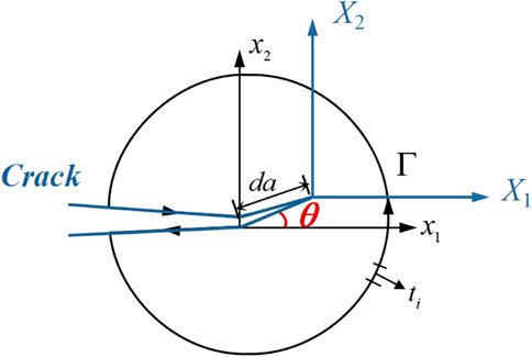
It is assumed that the crack will propagate with a kinking angle θ and length da, as depicted in Figure 4. X (X1, X2) refers to a moving coordinate system with its origin at the crack tip. Hence, the corresponding relation between the fixed coordinate system x (x1, x2) and the moving coordinate system X (X1, X2) is represented as follows:
Applying the chain rule of differentiation to Eq. 40, there exists
On the basis of transformation relationships in Eqs. (40)–(41), the variation rate of the total energy with respect to the deflective crack can be obtained by algebraic operation of Eq. 22, namely,
After algebraic operations, the partial derivative terms of the crack length in Eq. 42 are eliminated through employing the boundary conditions in Eq. 24 and the constitutive relationships in Eq. 25. Thus, the energy release rate Gθ in Eq. 42 with respect to the deflective crack is further modified as
When crack initiation occurs along the kinking angle θ, it is identified in Eq. 43 that the energy release rate Gθ is composed of two terms, i.e.,
where GΙ and GΙΙ stand for the energy release rate of crack growth along
Also, GΙΙ is regarded as the total energy release rate of crack propagation along the vertical direction of the crack, i.e.,
Variations in temperature, fission product concentration, fission rate, and mechanical strain with the crack length and kinking angle have been taken into account in the formulation of Eq. 46. The deflective crack propagates along the direction where the total energy release rate Gθ reaches maximum, i.e.,
In the I-TDM coupling system, the energy release rate Gθ can be utilized to predict crack kinking, assess integrity, and analyze strength of materials under irradiation. The initiation of crack growth occurs when the total energy release rate reaches a critical magnitude. Then, the crack will propagate along the deflective direction where Gθ is maximum. The total energy release rate Gθ with respect to deflective cracks is a supplement for investigating distinct cracking behaviors induced by irradiation.
Numerical implementation method of the energy release rate
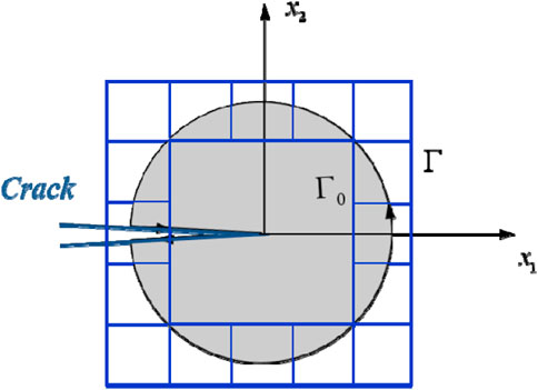
Based on the proposed model in this study, the energy release rate, which can be denoted as J-integral, was numerically implemented by FEM to characterize the driving force near the crack tip in the I-TDM coupling system. According to the equivalent domain integral method (Shivakumar and Raju, 1992; Nikishkov and Atluri, 2010; Wei et al., 2021), the conservative integral is calculated by replacing the closed integral path with a limited domain around crack tips, as depicted in Figure 5. Then, the numerical implementation corresponding to any closed integral path is performed using the Gauss integral method. Through combining the numerical calculation method with finite element post-processing, the J-integral can be calculated by script operation.
When employing the equivalent domain integral method, the integral domain A must be determined first. Since the calculated results within elements are definitive in the finite element simulation, the boundary of the integral domain, namely, Γ0 and Γ, is selected on the edge of the finite elements, as shown in Figure 5. It is noted that Γ0 can be settled either coincident or not coincident with the crack tip. If it is coincident, the integral domain is the region A included in boundary Γ.
By introducing the J-integral of Eq. 32 and a test function q (x1, x2), the energy release rate within the domain A is depicted taking the form of
For the four-node isoparametric element in FEM, an element-wise interpolation of the test function q (x1, x2) is represented as (Li et al., 2016)
where Ni and
Through utilizing the Gauss integral method, the J-integral within one element is represented by the sum of function values at Gaussian points (ri,si), i.e.,
where det (Je) denotes the determinant of the Jacobian matrix in the current element.
By accumulative calculation of the integral value Je for every element in the integral domain of Figure 5, the energy release rate corresponding to the given closed integral path is depicted as
Analysis of the central crack model in the I-TDM coupling system
Grade 304 stainless steel (304SS) is commonly utilized as the reactor component material, metal matrix, and the shell of the dispersion fuel element. The magnitude of irradiation damage is as low as 0.00001 dpa for structural components and can be up to over 10 dpa for the matrix of the dispersion fuel element. Under neutron irradiation, the cracking behaviors in materials will seriously threaten the safety of reactors. As an application of the proposed method, an irradiated 304SS sheet model with a central crack was simulated and investigated under uniaxial tension.
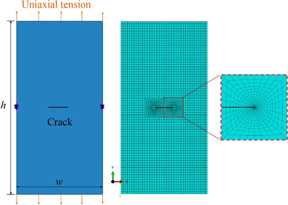
A user-defined material subroutine was coded and applied in finite element simulation according to the constitutive relationships in Eq. 25. The finite element model is presented in Figure 6. A two-dimensional crack model with length l = 100 mm, width w = 50 mm, and a central crack a=11 mm was simulated using the finite element program ABAQUS/CAE. The loading conditions included displacement tension Δh, temperature field, and irradiation. By mesh refinement at the crack tip, the calculated accuracy and convergence were improved. The effect of mesh size was eliminated by the mesh-independence analysis. Through post-processing of the stress fields, the strain fields, and the energy density fields near the crack tip, the energy release rate can be calculated according to the presented model.
The coupling coefficients in Eq. 32 will be simplified in numerical calculations. Material properties were settled according to the experimental data of 304SS (Spino et al., 2003; Monnet and Mai, 2019). The yield strength is about 250 MPa for unirradiated 304 stainless steel. The simulated temperatures were all set at 50oC. The irradiation conditions were represented as the irradiation damage, namely, the displacement per atom of dpa = 0, dpa = 2.0, dpa = 3.4, and dpa = 5.0, respectively. The thermal-diffusion coupling coefficient was assumed to be 1, namely, the thermal effect was not coupled with the diffusion effect. Also, the impact of the thermal effect and the diffusion effect on mechanical deformations was assumed to be identical, namely, the thermal-mechanical coefficient and the diffusion-mechanical coefficient were both set to 0.5. All corresponding parameters and coefficients are detailed in Table 1.
Figure 7 shows the Mises stress fields at the crack tip under different irradiation conditions (i.e., the displacement per atom (dpa)). The Mises stress increases with elevated displacement per atom. Compared with unirradiated materials, the yield stress reflected by Mises stress increases with an increase in irradiation dosage, which is consistent with the irradiation effects observed in experiments (Boyne et al., 2013). Thus, irradiation enhances the stress concentration of the crack tip.
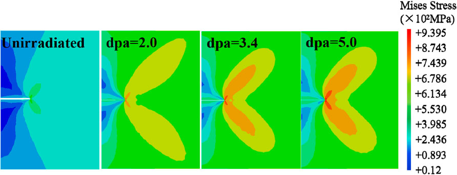
FIGURE 7. Contour plot of Mises stress fields at the crack tip under different displacement per atom (dpa) values.
Under different irradiation conditions, the energy release rate was solved by post-processing of the stress fields, the strain fields, and the strain energy density fields near the crack tip. Figure 8 shows the calculation results of the energy release rate near the crack tip under different displacement per atom (dpa) values. As depicted in Figure 8A, for unirradiated materials, the energy release rate calculated by the numerical implement of FEM is consistent with values obtained by conventional analytical solutions (Rice, 1968). Thus, the numerical implementation method was validated to be accurate. The presented model can be employed to numerically calculate the energy release rate in the I-TDM coupling system. Additionally, the variation in the energy release rate at the crack tip with respect to deformation monotonously increases under irradiation and is all greater than that in unirradiated materials.
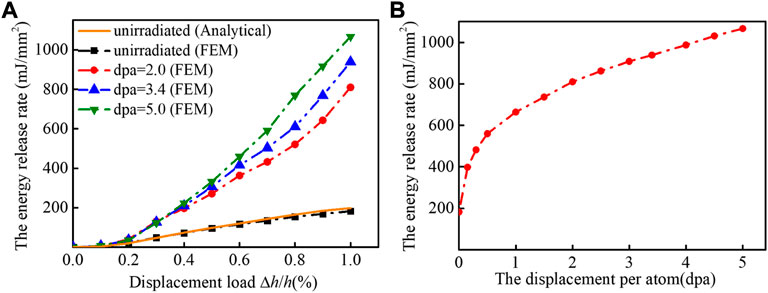
FIGURE 8. Variation of the energy release rate G with (A) deformation and (B) the displacement per atom (dpa).
As depicted in Figure 8B, the energy release rate increases with an increase in amount of irradiation. The sigmoidal dependence of the energy release rate on irradiation has been observed. At the regime of the low irradiation level, the energy release rate increased sharply. Variation in GI declined with the increase in displacement per atom. The effect of irradiation on the material is essential due to the evolution of microstructures. However, the fracture toughness declines with irradiation promoting according to experiments (Maloy et al., 2001). The propagation of the crack begins when the energy release rate reaches the fracture toughness of materials. So irradiation makes material crack easier, i.e., irradiation enhances cracking behaviors in materials. Consequently, in the I-TDM coupling system, the presented model can be utilized to solve the physical fields and the energy release rate near the crack tip under irradiation and to investigate the deformation, the cracking, the failure, and the integrity problems of irradiated materials.
Conclusion
The energy release rate in the I-TDM coupling system has been developed and numerically implemented by FEM for investigating cracking and failure problems of irradiated materials. The main conclusions are as follows:
1) Taking into account of the irradiation-induced temperature, the diffusion concentration, and the mechanical strain, the variation in the total energy and the constitutive relationship in the I-TDM coupling system can be derived according to the thermodynamically consistent method and the principle of minimum potential energy under irradiation.
2) By characterizing the variation rate of the total energy with respect to crack propagation, the energy release rate near the crack tip in irradiated materials was formulated and employed for predicting crack propagation and deflection. The J-integral corresponding to the energy release rate G in the I-TDM coupling system was verified to be path-independent.
3) Through implementing the presented model in the frame of the finite element method, the physical fields and the energy release rate near the crack tip were numerically calculated and validated to be accurate by comparison with the analytical solutions. Irradiation will promote the stress concentration near the crack tip and enhance the cracking behavior of materials.
Data availability statement
The raw data supporting the conclusion of this article will be made available by the authors, without undue reservation.
Author contributions
YD is the first author of this manuscript. She established the presented model, analyzed the numerical results, and drafted the manuscript. HZ interpreted the calculated method and simulated results.
Funding
This work was supported by the Natural Science Foundation of China (11772245), the Youth Science and Technology Innovation Team Project of China National Nuclear Corporation (JT211), the Fund of Science and Technology on Reactor System Design Technology Laboratory (LRSDT2020108), the Project of Nuclear Power Institute of China (No.KDY191-04-FW-HT-2021 003), and the Innovative Scientific Program of CNNC. The computation made use of the high-performance computing (HPC) platform of Xi’an Jiaotong University.
Conflict of interest
The authors declare that the research was conducted in the absence of any commercial or financial relationships that could be construed as a potential conflict of interest.
Publisher’s note
All claims expressed in this article are solely those of the authors and do not necessarily represent those of their affiliated organizations, or those of the publisher, the editors, and the reviewers. Any product that may be evaluated in this article, or claim that may be made by its manufacturer, is not guaranteed or endorsed by the publisher.
References
Bai, X. M., Voter, A. F., Hoagland, R. G., and Uberuaga, B. P. (2010). Efficient annealing of radiation damage near grain boundaries via interstitial emission. Science 327, 1631–1634. doi:10.1126/science.1183723
Bouklas, N., Landis, C. M., and Huang, R. (2015). Effect of solvent diffusion on crack-tip fields and driving force for fracture of hydrogels. J. Appl. Mech. 396, 6–83. doi:10.1115/1.4030587
Boyne, A., Shen, C., Najafabadi, R., and Wang, Y. (2013). Numerical simulation of irradiation hardening in zirconium. J. Nucl. Mater. 438 (1-3), 209–217. doi:10.1016/j.jnucmat.2013.03.035
Cai, X. Z., and Guo, Z. S. (2020). Coupled mechano-diffusion J-integral in active particles under the influence of binder. Eng. Fract. Mech. 231, 107031. doi:10.1016/j.engfracmech.2020.107031
Cherepanov, G. P. (1967). Crack propagation in continuous media. J. Appl. Math. Mech. 31, 503–512. doi:10.1016/0021-8928(67)90034-2
Gao, Y. F., and Zhou, M. (2013). Coupled mechano-diffusional driving forces for fracture in electrode materials. J. Power Sources 230, 176–193. doi:10.1016/j.jpowsour.2012.12.034
Granberg, F., Nordlund, K., Ullah, M. W., Jin, K., Zhang, Y., Bei, H., et al. (2016). Mechanism of radiation damage reduction in equiatomic multicomponent single phase Alloys. Phys. Rev. Lett. 116, 135504. doi:10.1103/PhysRevLett.116.135504
Guo, Y., and Li, Q. (2017). Material configurational forces applied to mixed mode crack propagation. Theor. Appl. Fract. Mech. 89, 147–157. doi:10.1016/j.tafmec.2017.02.006
Hall, M. M., and Flinn, J. E. (2016). Stress state dependence of in-reactor creep and swelling. Part 2: Experimental results. J. Nucl. Mater. 396, 119–129. doi:10.1016/j.jnucmat.2009.10.064
Hu, S. L., and Shen, S. P. (2013). Non-equilibrium thermodynamics and variational principles for fully coupled thermal–mechanical–chemical processes. Acta Mech. 224, 2895–2910. doi:10.1007/s00707-013-0907-1
Jeong, G. Y., Kim, Y. S., and Sohn, D. S. (2015). Mechanical analysis of UMo/Al dispersion fuel. J. Nucl. Mater. 466, 509–521. doi:10.1016/j.jnucmat.2015.07.033
Kim, Y. S., Hofman, G. L., and Ryu, H. J. (2006). Correlation development for the interdiffusion layer growth in (U-Mo)/Al dispersion nuclear fuel. Defect. Diffus. Forum. 258-260, 176–181. doi:10.4028/www.scientific.net/ddf.258-260.176
Kim, Y. S., Jeong, G. Y., Sohn, D. S., and Jamison, L. M. (2016). Pore growth in U-Mo/Al dispersion fuel. J. Nucl. Mater. 478, 275–286. doi:10.1016/j.jnucmat.2016.06.029
Kuroda, M., Yamanaka, S., Nagase, F., and Uetsuka, H. (2001). Analysis of the fracture behavior of hydrided fuel cladding by fracture mechanics. Nucl. Eng. Des. 203, 185–194. doi:10.1016/S0029-5493(00)00323-X
Li, Q., and Kuna, M. (2012). Inhomogeneity and material configurational forces in three dimensional ferroelectric polycrystals. Eur. J. Mech. - A/Solids 31, 77–89. doi:10.1016/j.euromechsol.2011.07.004
Liu, J., Fan, G., Han, P., Ge, D., and Qiao, G. (2009). Thermal deformation behavior and microstructure of nuclear austenitic stainless steel. Sci. China Ser. E-Technol. Sci. 52 (8), 2167–2171. doi:10.1007/s11431-009-0215-0
Liu, Y., Huang, Q., Xue, H., Crespillo, M. L., Liu, P., and Wang, X. (2018). Thermal spike response and irradiation-damage evolution of a defective YAlO3 crystal to electronic excitation. J. Nucl. Mater. 499, 312–316. doi:10.1016/j.jnucmat.2017.11.052
Long, C. S., Zhao, Y., Gao, W., Xiao, H., and Wei, T. (2014). A model for cracking of ceramic fuel particles in dispersion fue, Nucl. Power. Eng. 35, 922–96E.
Lowe, T., Bradley, R. S., Yue, S., Barii, K., Gelb, J., Rohbeck, N., et al. (2015). Microstructural analysis of TRISO particles using multi-scale X-ray computed tomography. J. Nucl. Mater. 461, 29–36. doi:10.1016/J.JNUCMAT.2015.02.034
Maloy, S. A., James, M. R., Willcutt, G., Sommer, W. F., Sokolov, M., Snead, L. L., et al. (2001). The mechanical properties of 316L/304L stainless steels, Alloy 718 and Mod 9Cr–1Mo after irradiation in a spallation environment. J. Nucl. Mater. 296, 119–128. doi:10.1016/s0022-3115(01)00514-1
Monnet, G., and Mai, C. (2019). Prediction of irradiation hardening in austenitic stainless steels: Analytical and crystal plasticity studies. J. Nucl. Mater. 518, 316–325. doi:10.1016/j.jnucmat.2019.03.001
Nikishkov, G. P., and Atluri, S. N. (2010). Calculation of fracture mechanics parameters for an arbitrary three-dimensional crack, by the ‘equivalent domain integral’ method. Int. J. Numer. Methods Eng. 24 (9), 1801–1821. doi:10.1002/nme.1620240914
Nikolaevskij, V. N. (1982). Path-independent rate integrals and the criterion of steady crack growth in inelastic bodies. Eng. Fract. Mech. 28, 275–282. doi:10.1016/0013-7944(87)90221-9
Nikolaos, B., Chad, M. L., and Rui, H. (2015). Effect of solvent diffusion on crack-tip fields and driving force for fracture of hydrogels. J. Appl. Mech. 396 (8), 64–83. doi:10.1115/1.4030587
Noori-kalkhoran, O., and Gei, M. (2020). Evaluation of neutron radiation damage in zircaloy fuel clad of nuclear power plants: A study based on pka and dpa calculations. Prog. Nucl. Energy 118, 103079. doi:10.1016/j.pnucene.2019.103079
Nordlund, K., Zinkle, S. J., Sand, A. E., Granberg, F., Averback, R. S., Stoller, R. E., et al. (2018). Primary radiation damage: A review of current understanding and models. J. Nucl. Mater. 512, 450–479. doi:10.1016/j.jnucmat.2018.10.027
Rice, J. R. (1968). A path independent integral and the approximate analysis of strain concentration by notches and cracks. J. Appl. Mech. 35, 379–386. doi:10.1115/1.3601206
Ricoeur, A., and Kuna, M. (2008). The thermoelectromechanical J-integral and the thermal permeability of cracks. Key Eng. Mat. 385-387, 569–572. doi:10.4028/www.scientific.net/kem.385-387.569
Samala, M. K., Sanyalb, G., and Chakravartty, J. K. (2010). Estimation of fracture behavior of thin walled nuclear reactor fuel pins using pin-loading-tension (PLT) test. Nucl. Eng. Des. 240, 4043–4050. doi:10.1016/j.nucengdes.2010.09.030
Shivakumar, K. N., and Raju, I. S. (1992). An equivalent domain integral method for three-dimensional mixed-mode fracture problems. Eng. Fract. Mech. 42 (16), 935–959. doi:10.1016/0013-7944(92)90134-Z
Spino, J., Cobos-Sabate, J., and Rousseau, F. (2003). Room-temperature micro-indentation behaviour of LWR-fuels, Part 1: Fuel micro-hardness. J. Nucl. Mater. 322, 204–216. doi:10.1016/S0022-3115(03)00328-3
Suo, Y. H., and Shen, S. P. (2012). Dynamical theoretical model and variational principles for coupled temperature-diffusion-mechanics. Acta Mech. 223, 29–41. doi:10.1007/s00707-011-0545-4
Suzuki, S., and Kobayashi, Y. (2008). Threshold energy of low-energy irradiation damage in single-walled carbon nanotubes. Jpn. J. Appl. Phys. 47, 2040–2043. doi:10.1143/JJAP.47.2040
Wang, Q., Cui, Y., Huo, Y., and Ding, S. (2011). Simulation of the coupling behaviors of particle and matrix irradiation swelling and cladding irradiation growth of plate-type dispersion nuclear fuel elements. Nucl. Fuel Elem. Mech. Mat. 43, 222–241. doi:10.1016/j.mechmat.2011.01.004
Wei, W., Yang, Q. S., Liang, J. C., Guo, S. J., and Ma, L. H. (2021). Theory and calculation of the mixed-mode fracture for coupled chemo-mechanical fracture mechanics. Theor. Appl. Fract. Mech. 112102817, 102817. doi:10.1016/j.tafmec.2020.102817
Yu, P., Chen, J., Wang, H., Liang, X., and Shen, S. (2018). Path-independent integrals in electrochemomechanical systems with flexoelectricity. Int. J. Solids Struct. 147, 20–28. doi:10.1016/j.ijsolstr.2018.04.006
Zuo, G., and Chen, H. (2018). Path-dependent J-integrals under mixed-mode loads of mode I and mode II. Theor. Appl. Fract. Mech. 96, 380–386. doi:10.1016/j.tafmec.2018.05.014
Nomenclature
Keywords: energy release rate, crack, irradiation, thermo-diffusion-mechanical coupling system, J-integral
Citation: Dong Y, Zhou Y, Tang C, Lu H and Zuo H (2022) The energy release rate of crack growth in an irradiation-induced thermo-diffusion-mechanical (I-TDM) coupling system. Front. Mater. 9:1031925. doi: 10.3389/fmats.2022.1031925
Received: 30 August 2022; Accepted: 03 October 2022;
Published: 04 November 2022.
Edited by:
Linyun Liang, Beihang University, ChinaCopyright © 2022 Dong, Zhou, Tang, Lu and Zuo. This is an open-access article distributed under the terms of the Creative Commons Attribution License (CC BY). The use, distribution or reproduction in other forums is permitted, provided the original author(s) and the copyright owner(s) are credited and that the original publication in this journal is cited, in accordance with accepted academic practice. No use, distribution or reproduction is permitted which does not comply with these terms.
*Correspondence: Hong Zuo, enVvaG9uZ0BtYWlsLnhqdHUuZWR1LmNu
 Yingxuan Dong
 Yi Zhou2