 Yanwen Li
 Decai Li
 Yingsong Li
94% of researchers rate our articles as excellent or good
Learn more about the work of our research integrity team to safeguard the quality of each article we publish.
Find out more
ORIGINAL RESEARCH article
Front. Mater. , 12 October 2022
Sec. Smart Materials
Volume 9 - 2022 | https://doi.org/10.3389/fmats.2022.1011550
This article is part of the Research Topic Characterization and Application of Magneto-sensitive Soft Materials View all 20 articles
With the rapid development of aerospace technology, the vibration problem of the spacecraft flexible structure urgently needs to be solved. Magnetic fluids are a type of multi-functional smart materials, which can be employed in shock absorbers to eliminate these vibrations. Referring to the calculation methods of stiffness coefficients of other passive dampers, the stiffness coefficient formula of magnetic fluid shock absorbers (MFSAs) was derived and refined. Meanwhile, a series of varying stiffness magnetic fluid shock absorbers (VS-MFSAs) were proposed and fabricated based on the second-order buoyancy principle. The range of stiffness coefficients covered by these VS-MFSAs contains the optimal stiffness coefficient estimated by formulas. The repulsive force measurement and vibration attenuation experiments were conducted on these VS-MFSAs. In the case of small amplitude, the relationship between the repulsive force and the offset distance was linear, which means the stiffness was linear. The simulation and experiment curves of the stiffness were in good agreement. The results of vibration attenuation experiments demonstrated that the rod length and the magnetic fluid mass influence the damping efficiency of VS-MFSAs. In addition, these results verified that the VS-MFSA with the optimal stiffness coefficient performed best. Therefore, the stiffness coefficient formula can guide the design of MFSAs.
The vibration problem of the spacecraft’s flexible solar panel is one of the most critical issues for the normal operation of spacecrafts (Jiang and Li, 2010). The solar panels are susceptible to residual oscillation and driving disturbance (Jiang and Li, 2011), because of their characteristics of small damping and low frequency, which results in vibration. These micro-vibrations are difficult to reduce in the space environment so that vibration suppression of spacecraft’s flexible structures has received a lot of attention in the past two decades (Hu et al., 2020).
One promising solution for this problem is to utilize shock absorbers with smart materials. Magnetic fluids (MFs) are a kind of smart materials, which are composed of nanoparticles, carrier liquids and surfactants (Rosensweig, 1987). Due to their chemical composition, MFs have a lot of good characteristics, such as rapid magnetic response, complex rheology, amazing levitation and so on (Rosensweig, 1966). According to these interesting properties, magnetic fluid shock absorber (MFSA) has many advantages, for instance, controllable damping, compact structure, high sensitivity, less energy consuming and long life, etc. (Li and Li, 2022a) These good features make MFSAs suitable for vibration suppression with low frequency and small amplitude. Magnetorheological fluids (MRFs) which were first prepared by Rabinow (Rabinow, 1948) in 1948 are easily confused with MFs. Unlike nano-scale magnetic particles in MFs, the particles in MRFs are micro-scale, so that these particles are more prone to aggregation and deposition (Li et al., 2022). As a result, the stability of MFs is much better than that of MRFs. Meanwhile MRFs possess stronger shear viscosity and yield stress than MFs. Based on these interesting characteristics of MRFs, they are usually used for vibration suppression of medium or high frequencies (Xu et al., 2021; Yang et al., 2021).
The first successful application of the MF viscous damper was presented by NASA in 1967, which was employed to suppress the oscillations of the Radio Astronomy Explorer Satellite in aerospace (Coulombre et al., 1967). Afterwards, MF dampers attracted more and more attention and scholars from various countries devoted great efforts to the development of MF dampers (Li et al., 2022). Ten years later, on the basis of levitation characteristics of MFs, Moskowitz et al. (Moskowitz et al., 1978) proposed a viscous fluid inertia damper working well in reducing the rotational vibrations of stepping motor shafts. In 2002, Bashtovoi et al. (Bashtovoi et al., 2002) created a novel MF dynamic absorber, which was regarded as a major breaktrough for dampening the spacecraft vibration. In order to improve its sensitivity, this MF dynamic absorber wasn’t filled with MFs, which played an important role in subsequent development of MF inertia dampers. In the same period, on account of the controllable flow of MFs, researchers replaced ordinary liquids in tuned liquid dampers with MFs to raise their damping efficiency, which were called tuned MF dampers (Ohno et al., 2008; Ohno and Sawada, 2010; Ohno et al., 2011). Due to the aggravation of energy problems, energy harvesting has received increasing attention. Vibration energy harvesters have become a hotspot for studies on MF dampers in the past decade (Bibo et al., 2012; Choi et al., 2015). They are combination of energy harversters and MF dampers and can realize self-energizing, which boosts the development of equipment miniaturization (Seol et al., 2017). In the previous extensive literature, the damping coefficient of MF dampers has always been concerned (Li and Li, 2022b). However, there are far fewer studies involving stiffness coefficient.
Fortunately, there are sufficient studies on the stiffness coefficients of other dampers. The research approaches about stiffness coefficients in these studies can be transferred to MF dampers. Sun et al. (Sun et al., 2015) presented a novel compact shock absober with variable stiffness, which was suitable for vehicle suspension. Its stiffness was controlled by current applied to the shock absorber. Wang et al. (Wang et al., 2021) proposed a new tuned inerter negative stiffness damper for protecting primary structures under earthquake excitaions. Its negative stiffness combined with inertance were employed to enhance the energy dissipation ratio. Javanbakht et al. (Javanbakht et al., 2018) developed an analytical model to refine damper design by considering the negative and positive stiffness. The important parameters of negative stiffness dampers and positive stiffness dampers were predicted by the refined design formula. These design tools made dampers more sutiable to mitigate vibrations of stay cables. Weber et al. (Weber et al., 2010) created a novel adaptive tuned mass damper, of which damping and stiffness can be adjusted. This damper contained a magnetorheological damper that was used to control friction-viscous damping and stiffness of the whole damper. Combined with a controllable magnetorheological damper, this presented damper performed well over a wide frequency range.
In the paper, the optimal stiffness coefficient formula was derived in detail and a series of MF dampers with varying stiffness were presented. In section 2, the whole derivation process of the optimal stiffness coefficient was elaborated. Then, the design method of a new varying stiffness MF shock absorber (VS-MFSA) was proposed in section 3. Section 4 illustrated the experimental process and corresponding apparatus. The simulation and experiment results of repulsive force, as well as the vibration attenuation experiment results were given and discussed in section 5. Finally, the main conclusions were outlined in section 6.
The cantilevered elastic plate represented the simplified flexible solar panel of spacecrafts and generated maximum vibration at the end. Therefore, VS-MFSAs were generally placed at the end of plate, as shown in Figure 1A. Ulteriorly, the corresponding physical model was extracted from the experimental system model in Figure 1A, which was called two-degree-of-freedom oscillation model, as shown in Figure 1B.
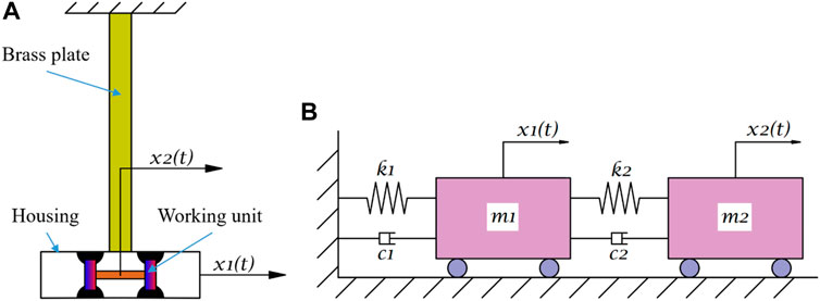
FIGURE 1. Simplified model. (A) Model of the experimental system. (B) Model of the oscillation system.
Based on the vibration theory, the motion equations of the oscillation system in Figure 1B are:
Where
According to the continuous beam theory, the equivalent stiffness coefficient of the brass plate can be expressed as,
Where
On the basis of the calculation method of the cantilever beam with a lumped mass at one end, the first-order natural frequency of the brass plate is,
Where
In order to facilitate the calculation, the sinusoidal excitation force and displacements are expressed in the form of complex variables function respectively.
By solving Equation Eq. 1 and applying
By adopting euler formula, the amplitude in the form of complex variables is subsitituted with the real amplitude and phase.
Where
By using Equation Eq. 6 which determains the amplitude ratio of the whole oscillation system, one of the most important parameters of VS-MFSAs, namely
In the case of ignoring the damping of the main system, which means that
When considering the damping of the main system, which means that
By putting into specific value, the optimal stiffness coefficient of the VS-MFSA was got, that is
Figure 2 depicts the section view of the VS-MFSA, including the major components and main dimensions. Meanwhile, Table 1 lists the main structural parameters, corresponding symbols and values. The VS-MFSA was designed on the basis of the second-order buoyancy principle of MFs. The connecting rod linked two moving magnets at both ends and the moving magnets adsorbed the MF, which formed the working unit. The MF was injected on each moving magnet respectively and wasn’t filling the housing, as the gray part shown in Figure 2. Considering the inertial force, the initial connecting rod was made of copper. In order to adjust the stiffness of VS-MFSAs, the length of connecting rod was altered. To mitigate the influence of mass change, resin was chosen as the material of added connecting rod. As vibrations were excited, the working unit leaved from the initial equilibrium position and then was subjected to the repulsive force generated by the static magnet. The static magnet was fastened with two fixing spacers and aligned with the moving magnets to avoid non-axial repulsive force. Moreover, the moving magnets were suspended in the MF because of the second-order buoyancy principle of MFs. The rubber rings were mounted on the fixing spacers to ensure the MF sealed. The housing adopted the split strucutre and was fabricated with holes using to balance the pressure in the cavity. When the working unit reciprocating in the housing, the movement caused the MF flow, which dissipated the oscillation energy. The whole appearance of the VS-MFSA is shown in Figure 3.
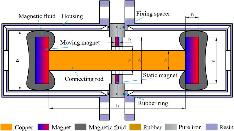
FIGURE 2. Section view of the varying stiffness magnetic fluid shock absorber.
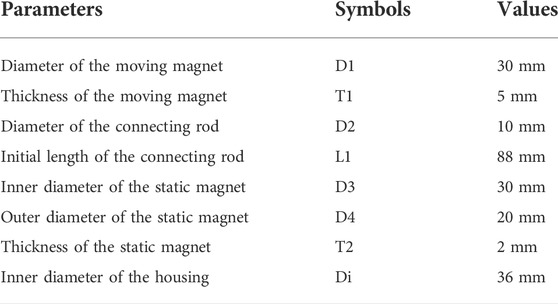
TABLE 1. Main structural dimensions of the varying stiffness magnetic fluid shock absorber.
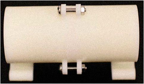
FIGURE 3. Appearance view of the varying stiffness magnetic fluid shock absorber.
It can be seen from Figure 4 that the vibration system was composed of a vibration table and a data acquisition system. The vibration table involved a base and a holder to immobilize one end of the brass plate. The other end of the brass plate was fitted with a frame using to install the VS-MFSA. The non-magnetic support stretched out from the holder for fixing the laser displacement sensor. The size of the cantilever elastic brass plate was 1100 mm*50 mm*5 mm, as well as the small amplitude and low frequency vibrations were generated by the plate. The frequency of the free oscillations of the cantilever elastic brass plate was equal to 1.18 Hz and the amplitude was set to 6 mm in the subsequent vibration reduction experiments. As for the data acquisition system, it included a acquisition card, a computer and an laser displacement sensor. The acquisition card USB-DAQ-7606i collected electrical signals and transmitted them to the computer with sampling frequency of 50 Hz. In order to meet the requirement of experiments, the laser displacement sensor HL-G108-A-C5 was chosen, of which the resolution was 2.5 mm.
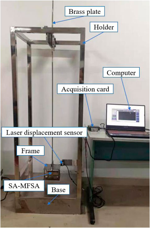
FIGURE 4. Photograph of experimental apparatus of vibration system.
The experiment apparatus shown in Figure 5 was employed to measure the repulsive force between the static magnet and moving magnets. The dynamometer was connected with the sliding table through the fixing plate. The eletronic slide gauge was concatenated with the sliding table to obtain the position of the dynamometer. The accuracies of the dynamometer and the eletronic slide gauge were 0.001 N and 0.01 mm, respectively. The static magnet was fixed on the base made of resin, as well as the moving magnet was attached to the non-magnetic rod, which ensured the results weren’t affected by extra magnetic field. Besides, the non-magnetic rod, moving magnets and the static magnet were coaxial. First, we made the connecting rod center coincide with the static magnet center by adjusting the lifting platform and the sliding table, then set the dynamometer to zero. Second, rotating the rocking handle let moving magnets leave the equilibrium position and controlled the movement step length at 0.2 mm. In the end, the offset distances and corresponding repulsive forces were transmitted to the computer for subsequent analysis.
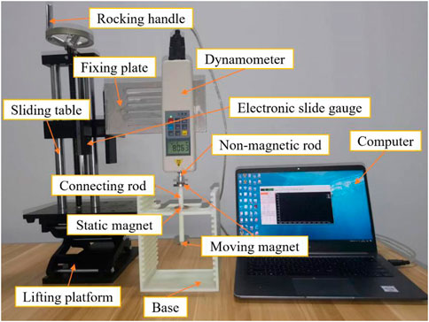
FIGURE 5. Photogragh of experimental apparatus to measure repulsive force.
The MF used in experiments was prepared by our laboratory, of which the density, viscosity and saturation magnetization were 1.23g/cm3, 0.26Pa s and 450Gs, respectively. Figure 6 gave the magnetization curve of the MF.
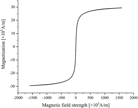
FIGURE 6. Magnetization curve of the magnetic fluid used in experiments.
The length range of the connecting rod was 88 mm–112 mm and the increment between adjacent rods was 4 mm. The static magnet and the working unit with adjustable connecting rod, of which dimensions were same as Table 1, were put into COMSOL for simulation. Since moving magnets were subjected to repulsive force, the magnetic flux direction of moving magnets was set opposite to that of static magnet. Under the transient mode, the magnetic scalar potential was set to ensure the simulation convergence and a model was built as Figure 7 for parametric scanning to obtain the simulation results.
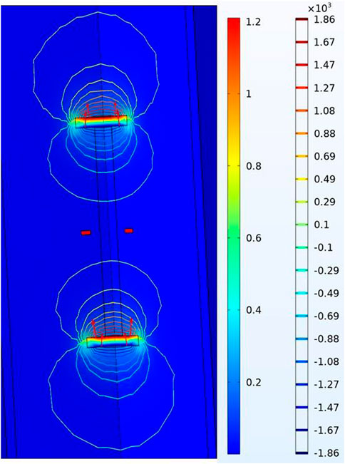
FIGURE 7. Simulated magnetic flux density of the working unit. [unit T].
As a result, the relationship between the repulsive force and the offset distance was obtained and shown in Figure 8. The experimental curves described the relationship between the repulsive force and the offset distance in Figure 9, which were measured by experimental apparatus in Figure 5. The offset distance was adjusted from 0 to 12 mm and the interval was 0.1 mm. Since the minimum reading of the dynamometer was 0.02N, all experimental curves started from the repulsive force equal to 0.02 N. The maximum amplitude of vibration reduction experiments was only 6mm, so actual offset distance would not exceed 6 mm. This ensured the distance between moving magnets and the static magnet was long enough. In this case, the repulsive force can be seen as linear with the offset distance, which means that the stiffness can be simplified to linear, as shown in Figure 8 and Figure 9. Therefore, the equation of stiffness coefficient can be approximated as:
Where
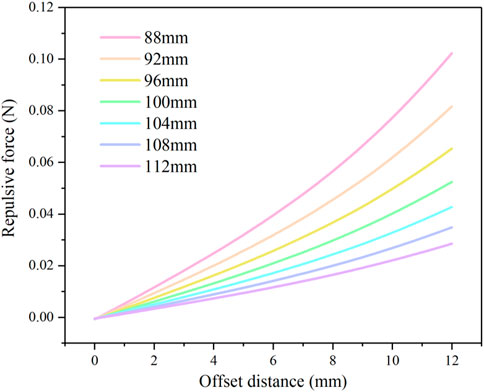
FIGURE 8. Simulated repulsive forces for different offset distances with various rod lengths.
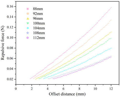
FIGURE 9. Measured repulsive forces for different offset distances with various rod lengths.
The simulation and experiment results of the stiffness coefficient with different rod lengths were calculated separately by equation Eq. 11. When rod length was equal to 108mm, the simulation and experiment resluts of the stiffness coefficient were 5.05N/m and 5.15N/m, respectively. Both results were close to the analytical solution 5.25N/m. At the same time, it can be seen from Figure 10 that the simualtion and experiment results were in good aggrement, especially when the rod lengths were taken from 96 to 108 mm. This illustrated that it was feasible to design VS-MFSA structure according to the optimal stiffness coefficient. The specific operation steps were: 1) First, through the theoretical model, the optimal stiffness coefficient was estimated. 2) Second, the VS-MFSA structure was designed based on simulation, which meant that adjusting the rod length made the optimal stiffness coefficient included within the rod length range. 3) Finally, the corresponding VS-MFSAs were fabricated and the correctness was verified by experimental apparatus in Figure 5.
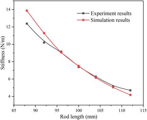
FIGURE 10. Compared simulation and experiment results of stiffness.
The results of the vibration attenuation experiments were described in terms of the attenuation time and the attenuation amplitude, respectively. From the perspective of attenuation time, vibration attenuation rate
Where
It can be seen from Figure 8 and Figure 9 that by altering the connecting rod length the stiffness coefficient of VS-MFSAs was also changed. Besides, the stiffness coefficient of VS-MFSAs with different connecting rod length can be calculated by Eq. 11. Therefore, the relationship between damping efficiency and stiffness coefficient can be expressed by the following curves of damping efficiency versus rod length. Figure 11 depicts the relationship between vibration attenuation rate and rod length under different amount of MF. It is obvious that vibration attenuation rate increased with rod length becoming longer. In addition, it reached maximum value as rod length taken 108 mm and would slightly decrease when rod length exceeded 108 mm. Regarding the amount of MF, the following two points were mainly considered. First, in order to ensure the stable suspension of the working unit, MF mass should be greater than minimum critical value. Second, if using too much MF, the moving magnet couldn’t fully adsorb MF and the extra MF might be bad for the performance of VS-MFSAs. Therefore, we chose 7–15 g MF on each moving magnet for experiments. It is observed that when MF ranged from 7 to 11 g, vibration attenuation rate continuously enhanced, which meant energy consumption became faster with more MF. However, when MF exceeded 11 g, vibration attenuation rate began to decrease. This was because too much MF hindered the working unit movement, which was detrimental to the damping performance.
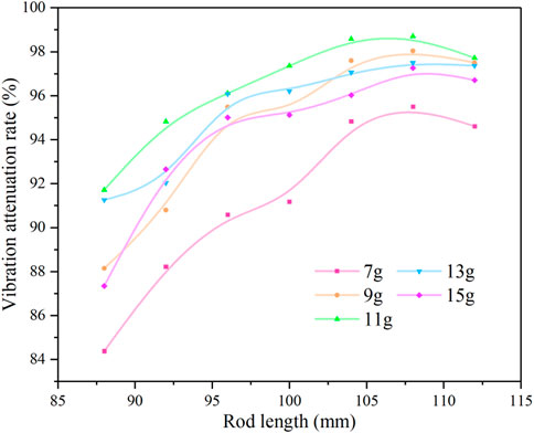
FIGURE 11. Vibration attenuation rate versus rod length with different magnetic fluid mass.
According to the attenuation amplitude, logarithmic decay rate, another dimensionless number was used to quantify the damping efficiency of VS-MFSAs, of which the calculation equation is as below.
Where
Figure 12 represents the dependence of logarithmic decay rate on rod length with different MF mass. Just like vibration attenuation rate, logarithmic decay rate also increased with rod lengthened. In the rod length range of 100–108 mm, logarithmic decay rate grew rapidly, but it dropped slowly as rod length longer than 108 mm. The peak of logarithmic decay rate also occurred at rod length equal to 108 mm. As for the effect of MF mass on logarithmic decay rate was basically the same as that on vibration attenuation rate. In general, both vibration attenuation rate curve and logarithmic decay rate curve proved that the VS-MFSA presented the best damping performance with rod length taken 108 mm.
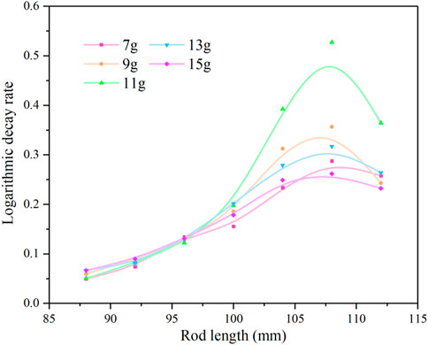
FIGURE 12. Logarithmic decay rate versus rod length with different magnetic fluid mass.
From the above experiment curves, it can be concluded that the connecting rod length and the MF mass significantly influenced the performance of VS-MFSAs. As a result, the VS-MFSA possessed the best damping performance with rod length taken 108 mm and MF equal to 11 g. In other words, when the rod length was adjusted to make the VS-MFSA got the optimal stiffness coefficient, the corresponding VS-MFSA performed best. Therefore, the refined optimal stiffness formula can guide the design of MFSAs. The vibration decay time of this optimal VS-MFSA was 9.27s and its vibration attenuation rate was up to 98.7%. Figure 13 shows displacement responses for initial excitation with the optimal VS-MFSA or equivalent mass, respectively. It is clearly that the vibration decay time in Figure 12A was only a seventieth compared with the decay time in Figure 12B.
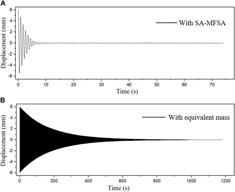
FIGURE 13. Displacement responses for initial excitation. (A) Response curve with VS-MFSA. (B) Response curve with equivalent mass.
Through the ratio b*/a*, our proposed VS-MFSA was contrasted with the previous similar MFSAs. It can be seen from Table 2 that the damping performance of our proposed VS-MFSA was significantly better than that of MFSAs mentioned in other references. This strongly suggested that stiffness coefficient had great influence on the performance of MFSAs so that the damping efficiency of the VS-MFSA with optimal stiffness was remarkably improved.
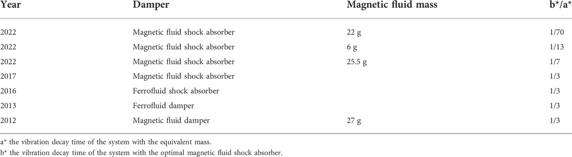
TABLE 2. Comparison of the optimal magnetic fluid shock absorbers.
The vibration problem of spacecraft flexible structure is the key issue obstructing advance in aerospace technology. The MFSA is one of the potential candidates for suppressing such vibration. In order to improve the damping performance of MFSAs, a new VS-MFSA was designed based on the stiffness coefficient formula. The specific conclusions were as follow.
1) According to the theoretical analysis of stiffness coefficients of other passive dampers, the stiffness coefficient formula which was suitable for MFSAs was got. Besides, the optimal stiffness coefficient was estimated to be equal to 5.25 N/m. Then, this value can guide the design of MFSAs.
2) A novel VS-MFSA was proposed, which possessed the varying stiffness by changing the connecting rod length. On the basis of 3D-printing, a series of VS-MFSAs were fabricated and their stiffness coefficient included the optimal value.
3) The repulsive force measurement was both simulated and verified by experiments. The simulation and experiment curves were in good agreement. Moreover, the relationship between the repulsive force and offset distance was linear in the small displacement section. It indicated that the rod length corresponding to the optimal stiffness coefficient can be decided by simulation first for subsequence experiments.
4) The vibration attenuation experiments were carried out and the damping performance of VS-MFSAs was evaluated by the vibration attenuation rate and logarithmic decay rate. As a result, the rod length had a significant influence on the damping efficiency of VS-MFSAs, which meant the stiffness coefficient played an important role in damping performance of VS-MFSAs. It was obvious that VS-MFSA with the optimal stiffness coefficient had the best damping performance.
In summary, the optimal stiffness coefficient can well guide the design of MFSAs. It is hope that the refined stiffness coefficient formula proposed by us can be applied in other liquid dampers in the future.
The original contributions presented in the study are included in the article/supplementary material, further inquiries can be directed to the corresponding author.
YaL: Conceptualization, Methodology, Validation, Formal analysis, Investigation, Data Cleansing, Writing, Review, Editing. DL: Funding Acquisition. YiL: Investigation, Writing.
This work was supported by the National Natural Science Foundation of China (Grant No. 51735006, 51927810 and U1837206) and Beijing Municipal Natural Science Foundation (Grant No. 3182013).
Author Yingsong Li is employed by China Productivity Center for Machinery Co., Ltd.
The remaining authors declare that the research was conducted in the absence of any commercial or financial relationships that could be construed as a potential conflict of interest.
All claims expressed in this article are solely those of the authors and do not necessarily represent those of their affiliated organizations, or those of the publisher, the editors and the reviewers. Any product that may be evaluated in this article, or claim that may be made by its manufacturer, is not guaranteed or endorsed by the publisher.
Bashtovoi, V. G., Kabachnikov, D. N., Kolobov, A. V., Samoylov, V., and Vikoulenkov, A. (2002). Research of the dynamics of a magnetic fluid dynamic absorber. J. Magnetism Magnetic Mater. 252, 312–314. doi:10.1016/s0304-8853(02)00599-1
Bibo, A., Masana, R., King, A., Li, G., and Daqaq, M. (2012). Electromagnetic ferrofluid-based energy harvester. Phys. Lett. A 376 (32), 2163–2166. doi:10.1016/j.physleta.2012.05.033
Coulombre, R. E., Schnee, L., and d'Auril, H., Feasibility study and model development for a ferrofluid viscous damper. Final report, contract No. NASS-9431, goddard space flight centre, Greenbelt, Maryland. Available at: https://ntrs. nasa. gov/citations/19680021013,1967.
Choi, Y., Ju, S., Chae, S. H., Jun, S., and Ji, C. H. (2015). Low-frequency vibration energy harvester using a spherical permanent magnet with controlled mass distribution. Smart Mat. Struct. 24 (6), 065029. doi:10.1088/0964-1726/24/6/065029
Hu, Y., Geng, Y., and Wu, B. (2020). Flexible spacecraft vibration suppression by distributed actuators. J. Guid. Control, Dyn. 43 (11), 2141–2147. doi:10.2514/1.g005190
Javanbakht, M., Cheng, S., and Ghrib, F. (2018). Refined damper design formula for a cable equipped with a positive or negative stiffness damper. Struct. Control Health Monit. 25 (10), e2236. doi:10.1002/stc.2236
Jiang, J., and Li, D. (2010). Optimal placement and decentralized robust vibration control for spacecraft smart solar panel structures. Smart Mat. Struct. 19 (8), 085020. doi:10.1088/0964-1726/19/8/085020
Jiang, J. P., and Li, D. X. (2011). Robust H∞ vibration control for smart solar array structure. J. Vib. Control 17 (4), 505–515. doi:10.1177/1077546310370688
Li, Y., Han, P., Li, D., Chen, S., and Wang, Y. (2022). Typical dampers and energy harvesters based on characteristics of ferrofluids. Friction, 1–22. doi:10.1007/s40544-022-0616-7
Li, Y., and Li, D. (2022). Hexagonal Structure Enhancing Damping Efficiency Inspired by Tree Frogs. Available at: https://chemrxiv.org/engage/chemrxiv/article-details/62833f2f7087675cfb554c87.
Li, Y., and Li, D. (2022). The dynamics analysis of a magnetic fluid shock absorber with different inner surface materials. J. Magnetism Magnetic Mater. 542. doi:10.1016/j.jmmm.2021.168473doi:168473
Moskowitz, R., Stahl, P., and Reed, W. R. Inertia damper using ferrofluid, United States patent US 19784123675 (1978).
Ohno, K., and Sawada, T. (2010). An effect of vertical sloshing on a fluid pressure and a surface displacement in a tuned magnetic fluid damper. Int. J. Appl. Electromagn. Mech. 33 (3-4), 1411–1416. doi:10.3233/jae-2010-1268
Ohno, K., Shimoda, M., and Sawada, T. (2008). Optimal design of a tuned liquid damper using a magnetic fluid with one electromagnet. J. Phys. Condens. Matter 20 (20), 204146. doi:10.1088/0953-8984/20/20/204146
Ohno, K., Suzuki, H., and Sawada, T. (2011). Analysis of liquid sloshing of a tuned magnetic fluid damper for single and co-axial cylindrical containers. J. Magnetism Magnetic Mater. 323 (10), 1389–1393. doi:10.1016/j.jmmm.2010.11.052
Rabinow, J. (1948). The magnetic fluid clutch. Transactions of the American Institute of Electrical Engineers 67, 1308–1315. doi:10.1109/T-AIEE.1948.5059821
Rosensweig, R. E. (1966). Buoyancy and stable levitation of a magnetic body immersed in a magnetizable fluid. Nature 210 (5036), 613–614. doi:10.1038/210613a0
Rosensweig, R. E. (1987). Magnetic fluids. Annu. Rev. Fluid Mech. 19 (1), 437–461. doi:10.1146/annurev.fl.19.010187.002253
Seol, M., Jeon, S., Han, J., and Choi, Y. K. (2017). Ferrofluid-based triboelectric-electromagnetic hybrid generator for sensitive and sustainable vibration energy harvesting. Nano Energy 31, 233–238. doi:10.1016/j.nanoen.2016.11.038
Sun, S., Deng, H., Du, H., Li, W., Yang, J., Liu, G., Alici, G., and Yan, T. (2015). A compact variable stiffness and damping shock absorber for vehicle suspension. Ieee. ASME. Trans. Mechatron. 20 (5), 2621–2629. doi:10.1109/tmech.2015.2406319
Wang, H., Gao, H., Li, J., Wang, Z., Ni, Y., and Liang, R. (2021). Optimum design and performance evaluation of the tuned inerter-negative-stiffness damper for seismic protection of single-degree-of-freedom structures. Int. J. Mech. Sci. 212, 106805. doi:10.1016/j.ijmecsci.2021.106805
Weber, F., Boston, C., and Maślanka, M. (2010). An adaptive tuned mass damper based on the emulation of positive and negative stiffness with an MR damper. Smart Mat. Struct. 20 (1), 015012. doi:10.1088/0964-1726/20/1/015012
Xu, Z. D., Yang, Y., and Wu, R. (2021). Experimentally-verified micromechanical model of MR gels based on planar current loop model. J. Eng. Mech. 147 (8), 04021044. doi:10.1061/(asce)em.1943-7889.0001952
Yang, Y., Xu, Z. D., Guo, Y. Q., Sun, C., and Zhang, J. (2021). Performance tests and microstructure‐based sigmoid model for a three‐coil magnetorheological damper. Struct. Control Health Monit. 28 (11), e2819. doi:10.1002/stc.2819
Keywords: magnetic fluid, shock absorber, optimal stiffness coefficient, vibration, spacecraft
Citation: Li Y, Li D and Li Y (2022) Performance tests and design of a series of magnetic fluid shock absorbers with varying stiffness based on optimal stiffness formula. Front. Mater. 9:1011550. doi: 10.3389/fmats.2022.1011550
Received: 04 August 2022; Accepted: 05 September 2022;
Published: 12 October 2022.
Edited by:
Xun Yu, New York Institute of Technology, United StatesReviewed by:
Ying-Qing Guo, Nanjing Forestry University, ChinaCopyright © 2022 Li, Li and Li. This is an open-access article distributed under the terms of the Creative Commons Attribution License (CC BY). The use, distribution or reproduction in other forums is permitted, provided the original author(s) and the copyright owner(s) are credited and that the original publication in this journal is cited, in accordance with accepted academic practice. No use, distribution or reproduction is permitted which does not comply with these terms.
*Correspondence: Decai Li, bGlkZWNhaUBtYWlsLnRzaW5naHVhLmVkdS5jbg==
Disclaimer: All claims expressed in this article are solely those of the authors and do not necessarily represent those of their affiliated organizations, or those of the publisher, the editors and the reviewers. Any product that may be evaluated in this article or claim that may be made by its manufacturer is not guaranteed or endorsed by the publisher.
Research integrity at Frontiers
Learn more about the work of our research integrity team to safeguard the quality of each article we publish.