 You Song1,2
 Huali Hao
94% of researchers rate our articles as excellent or good
Learn more about the work of our research integrity team to safeguard the quality of each article we publish.
Find out more
ORIGINAL RESEARCH article
Front. Mater., 12 January 2022
Sec. Structural Materials
Volume 8 - 2021 | https://doi.org/10.3389/fmats.2021.828001
This article is part of the Research TopicMulti-Scale Investigation on Fiber-Reinforced Composite Materials: From Structural Design, Property Characterization to Engineering ApplicationsView all 9 articles
The weak interfacial adhesion has significantly affected the durability, long-term reliability, and performance of glass fiber–reinforced epoxy composites. The coating of graphene and carbon nanotubes on the glass fiber can have a positive effect on the strength, toughness, and thermal insulation performance of glass fiber-reinforced composites. However, the strengthening mechanism of carbon nanomaterial coating on the interfacial adhesion between glass fiber and epoxy has not been fully explored. In this work, the effect of graphene and single-walled carbon nanotubes (SWCNTs) on the interfacial properties of the glass fiber–reinforced epoxy has been investigated at atomistic scale. The graphene and SWCNTs are sandwiched between epoxy and silica to study the debonding behavior of the sandwiched structures. It is found that the interfacial energy is significantly improved with the incorporation of graphene and SWCNTs between epoxy and silica, causing an obvious improvement in adhesion stress for graphene coating and in debonding displacement for SWCNT coating. Compared with the epoxy/silica without coatings where the silica and epoxy detach from the contact surface, the sandwiched structures display different failure modes. The sandwiched structure with graphene coating fails at the epoxy matrix close to the interface, exhibiting a cohesive failure mode because of the relatively stronger interfacial interactions. The structures with SWCNTs fail at the interface between silica and SWCNTs, representing an adhesive failure mode due to the interlocking between SWCNTs and polymer chains. This work provides a theoretical guideline to optimize the interface adhesion of coated glass fiber–reinforced epoxy via structure design and surface modification of coating materials.
Glass fiber–reinforced (GFR) epoxy resin has been widely used as insulating materials, adhesives, electronic packing materials, and matrices for functional composites because of its thermal stability, light weight, superior mechanical properties, excellent resistance to corrosion, and outstanding electrical insulation (Hu et al., 2018; 2018; Zhang et al., 2018). It is well known that the fiber/matrix interface guarantees the stress transfer from the weak matrix to the strong fiber, so the composite performance is largely dependent on the fiber/matrix adhesion (Yao et al., 2018). However, the stress transfer from the matrix to glass fiber (GF) often presents a challenge to exploit the reinforcement role of fibers completely (Ren et al., 2019; Rȳquilȳ et al., 2019; Shin et al., 2017; Zhang et al., 2019). Efficient load transfer by interfacial bond strength of fiber/matrix composite systems is an essential requirement for the development of high-performance GFR composites. Numerous research studies have been devoted to the surface modification of glass fiber, such as plasma treatment, chemical treatment, and electrochemical oxidation and polymerization, to improve the interfacial properties of composites (Yao et al., 2018; Yuan et al., 2018).
It is noteworthy that with the development of nanotechnology and nanoscience, nanocomposites have become an extremely active field of scientific research (Li et al., 2019). With the production and popularity of carbon nanomaterials, graphene and CNTs have attracted significant attention because of their excellent properties (Jamnani et al., 2015); they have been widely applied as the nanoscale reinforcement in the interphase region of composites to improve their interfacial properties (Dewapriya et al., 2019; Park et al., 2019). This is because the coating of CNTs or graphene can cause the interface mechanical interlocking between the fiber and the matrix (Jamnani et al., 2015). For example, it is found that the incorporation of CNT-coated glass fiber contributes to more than 30% improvement in Young’s modulus of the GFR epoxy (Rahaman et al., 2014), and GF with the graphene coating can have an increment of about 30% in fracture strength (Kamar et al., 2015). Although many experimental studies are dedicated to investigating the effect of carbon nanomaterial coating on mechanical properties of GFR epoxy, inherent mechanisms on the improvements and failures of such nanocomposites from an atomistic scale are still not identified due to the limitation on the study of dynamics at nanoscale by experimental approach.
Molecular dynamics (MD) simulations have been widely adopted to investigate physical behaviors of materials on the atomistic scale and allow an in-depth study of the interaction of molecules while controlling experimental variables (Hao et al., 2020a; Hao et al., 2017; Hao et al., 2018). MD simulations have become a powerful approach for exploring the dynamical processes of conformational changes and predicting mechanical properties, quantifying their relationship (Hao et al., 2020b; Hao et al., 2019). For example, the effect of CNT features including the CNT radii, axial direction, and the concentration on the interfacial adhesion between graphene and epoxy have been successfully analyzed by MD simulations (Sun et al., 2019). It is found that the epoxy resin incorporated with parallel multilayer graphene exhibits cohesive yield with strain localization and nano-void formation within the bulk polymer, while epoxy incorporated with graphene sheets oriented normal to the interface exhibits adhesive failure at the interface, leading to a more brittle behavior and steeper post-yield softening (Li et al., 2012). The details of surface modification on the structural evolution of the interface during deformation can be depicted, and the reason for the variation in the interfacial properties can be figured out by MD simulations.
The objective of this work is to investigate the effect of graphene and SWCNTs coating on the interfacial properties of GFR epoxy at atomistic scale, revealing the variation in the failure behavior and figuring out the underlying reason for the enhanced mechanical properties of GFR composites with carbon nanocomposites coated on GF. As silica is the major composite and accounts for more than half of the weight fraction in commercial S-glass fiber, the silica structure is employed to represent glass fiber in this work. The graphene and SWCNTs are sandwiched between epoxy and silica with the construction of the sandwiched structures. The interfacial debonding behavior of the sandwiched structures is analyzed by using the steered molecular dynamics simulations. The thickness of graphene and the length of SWCNTs are varied to study their effect on the interfacial properties. The snapshots of conformational changes are captured to figure out the reason for the variation in the interfacial properties with different coatings. Finally, the enhanced mechanism behind them is discussed.
The atomistic simulations start with the construction of full-atomistic models of crosslinked epoxy and silica in Accelrys Materials Studio (Accelrys Software Inc.: Materials Studio 2007). The MD simulations for computing the interfacial properties are performed using large-scale atomic/molecular massively parallel simulator (LAMMPS) (Plimpton, 1995). The conventional polymer consistent forcefield (PCFF) is chosen as it can predict the structural, conformational, and vibrational properties of a broad range of molecules in condensed phases and also has an experimentally comparable precision in predicting molecular properties in condensed phases (Fan et al., 2007; Pramanik et al., 2018). This potential has been successfully applied in the simulations of a wide range of organic and inorganic materials including silica and epoxy resin. In this work, PCFF is used to crosslink epoxy resin and to describe the interactions between crosslinked epoxy and silica, as well as interactions between epoxy and carbon nanomaterials such as SWCNTs and graphene. The details of the model construction and simulation procedures are presented.
In this study, the high-performance epoxy resin diglycidyl ether of bisphenol A (DGEBA) crosslinked with curing agent 4,4′-diaminodiphenyl sulphone (44DDS) is selected as the representative because of its relative high properties and widely commercial applications (Mohan, 2013; Moller et al., 2020). The molecular structures of DGEBA and 44DDS and the details of the crosslinking process are shown in Figure 1. The first step of crosslinking is that the C-O-C bond in epoxide groups is broken with the formation of a reactive CH2 site. The hydroxyl groups are attached at the activated CH2 site so that the condensation polymerization can occur between DGEBA and 44DDS. The stoichiometric mixing ratio of DGEBA to 44DDS is 2:1 with 400 monomers of DGEBA and 200 monomers of 44DDS. A cubic primitive cell with a length of 6.4 nm is constructed. The energy of the system are minimized using the conjugate gradient method and then equilibrated at 300 K in the canonical (NVT) ensemble for 1 ns, followed by another 1 ns of equilibration in the isothermal-isobaric (NPT) ensemble at 300 K and 1 atm. Subsequently, the equilibrated system is heated to 400 K for crosslinking. The condensation reaction occurs between the hydroxyl groups at the end of DGEBA and hydrogens in amine groups of 44DDS at 400 K. Following this, the condensation polymerization occurs between unreacted hydroxyl groups in opened epoxide group of the DGEBA monomer with the formation of epoxide group. The system is finally cooled down to 300 K for equilibration in NPT ensemble at 1 atm. After equilibration, the obtained crosslinked structure with a crosslinking degree of 85% is served as the initial structure of epoxy resin with a size of 6.4 nm × 6.4 nm × 6.4 nm. The density of the crosslinked epoxy is about 1.14 g/cm3, located in the range from 1.1 g/cm3 to 1.4 g/cm3, tested by experiments. The glass transition temperature of crosslinked epoxy and Young’s modulus are 489 K and 4.4 GPa, respectively. These are consistent with the experimental results and other computational results (Amariutei et al., 2018; Fu et al., 2019; Jin et al., 2020; Xie et al., 2018).
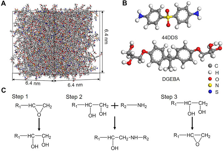
FIGURE 1. (A) Crosslinked epoxy resin with a size of 6.4 × 6.4 × 6.4 nm; (B) molecular structures of diglycidyl ether of bisphenol A (DGEBA) and curing agent 4,4′-diaminodiphenyl sulphone (44DDS); (C) steps for crosslinking where epoxide groups in DGEBA are activated and react with amine groups in 44DDS.
The silica structure is obtained by heating the crystalline β-cristobalite to high temperature for melting and then cooling down to room temperature (Leroch et al., 2012). Specifically, the β-cristobalite has a lattice constant of 7.16 Å with an oxygen-to-silicon ratio of 2:1, as shown in Figure 2A. The crystalline β-cristobalite system is cleaved on the (001) plane. The dangling oxygen atoms on the (001) surface are all saturated by the hydrogen atoms and dangling silicon atoms are saturated by hydroxyl groups, as shown in Figure 2B. The silica is first equilibrated at 300 K in the NVT ensemble for 1 ns and then equilibrated in the NPT ensemble at 300 K and 1 atm for another 1 ns with a periodic boundary condition applied to three directions. The equilibrated system is then heated to 5,000 K for 1 ns for melting in the NPT ensemble. Following this, the silica is cooled down to 300 K at a rate of 5 K/ps for equilibration. The density of constructed silica with a size of 6.4 nm × 6.4 nm × 2.4 nm is about 2.18 g/cm3, close to the experimental data (Shrivastava, 2018).
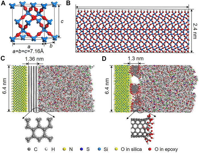
FIGURE 2. (A) Lattice unit of β-cristobalite as the initial structure of silica; (B) equilibrated silica structure with the surface covered by hydroxyl groups; equilibrated sandwiched systems coated by (C) graphene with four layers and (D) SWCNTs with a length of around 1.3 nm. The end of SWCNTs is saturated with carboxyl groups.
The cross-section areas of the aforementioned coating materials on the surface of silica including multi-layers of the graphene sheet and SWCNTs consisting of electrically neutral atoms are equal to the area of epoxy and silica. The carbon–carbon bond length in SWCNTs and graphene is 1.41 Å. The initial interlayer separation between individual graphene layers is 3.4 Å. The SWCNTs are of the (6,6) type with a diameter of 8.1 Å, and the end of SWCNTs are functionalized with carboxyl groups. The SWCNTs are vertically aligned on the surface of silica based on the experimental results (Rahaman et al., 2014; Rahmanian et al., 2013).
The silica is adhesive to the epoxy substrate with and without coating through the energy minimization and equilibration process. The equilibration of the epoxy/silica and the epoxy/coating/silica systems are performed at 300 K in the NVT ensemble for 1 ns, followed by another 1 ns under 300 K and 1 atm. The interlayer separation is initially selected to be 5 Å, which is subsequently adjusted by the repulsive and attractive forces at the interface. The root mean square displacement (RMSD) is checked, and it stays constant at the end of 500 ps, which indicates that the system is in an equilibrated state. In order to investigate the influence of the thickness of the graphene and length of SWCNTs coated on the interfacial properties between epoxy and silica, the number of graphene sheets is increased from one to four and the length of SWCNTs ranges from 1.3 nm (close to the thickness of four-layer graphene) to 6.3 nm. The shortest length of SWCNTs is for comparison with the result of graphene coating, and the longest length is close to the length of the interface surface. The examples of the equilibrated sandwiched structure coated with graphene and SWCNTs are shown in Figures 2C,D, respectively.
The steered molecular dynamics (SMD) developed based on MD is a powerful tool to investigate conformational dynamics at the interfacial domain (Sun et al., 2021). The method has been widely applied to examine the interface characteristics of various systems. In SMD simulations, the center-of-mass for epoxy and silica is attached by a virtual spring. The atoms are displaced by applying a constant velocity (v) to them; a restoring force is applied to atoms and the magnitude of the force is related to the spring constant (k). The epoxy and silica are debonded along the z direction under an equivalent opposite force perpendicular to the interface. The virtual spring force is determined by the following (Sun et al., 2021):
where t is the time; n is a unit vector for the direction of pulling; R(t) and R0 are the current and the initial displacements between the center-of-mass of epoxy and silica, respectively. U and F are the potential energy and virtual spring force, respectively. In this work, the pulling test is performed with a spring constant k of 100 kcal/(mol⋅Å2) and a velocity v of 1 Å/ps. The pulling force F measured by the displacement between the center-of-mass of epoxy and silica is collected every 0.1 fs, and then the adhesion stress is calculated by the following:
where Fmax is the maximum value of the virtual spring force for debonding, and A is the interface area which is about 6.4 nm × 6.4 nm. As the free energy change is equal to the work done on the system in a reversible isothermal process and therefore equal to the integral of an externally applied force over the coordinate, the free energy of the system changed along with the pulling displacement can be quantified. During SMD simulations, the potential of mean force (PMF) is simply another term for a free energy profile along the pulling displacement. Five independent simulations are conducted for debonding between epoxy and silica for all cases, and the averaged value is quantified. The conformational changes of the interface are captured with OVITO.
A virtual spring imposed on the center-of-mass between epoxy and silica moves separately for debonding, as shown in Figure 3A. The pulling displacement d is valued by the distance of center-of-mass between epoxy and silica. The pulling force F and PMF profile of the epoxy/silica system without coating as a function of pulling displacement d are shown in Figure 3B and C. According to the force profile, the debonding process can be divided into three stages. The force first increases rapidly to the maximum value (Fmax), followed by a sudden drop to around zero indicating the epoxy and silica completely debonded. The PMF reaches the local maxima when the force reduces to about zero. To better understand the variation of F and PMF during the debonding process, the interfacial energy (Einter) as a function of d is shown in Figure 3D. The interfacial interaction is reduced to zero at the end of the second stage also indicating the complete debonding between epoxy and silica. The conformational change at different stages is shown in Figure 3E. The detachment between polymer chains of epoxy and silica first occurs at the edge of the contact surface and propagates into the inner. The epoxy/silica system exhibits an adhesive failure mode.
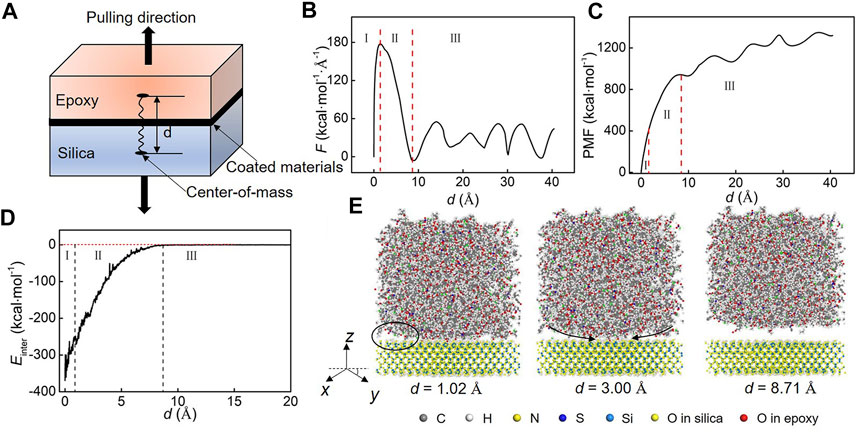
FIGURE 3. (A) Schematic diagram for interfacial debonding of epoxy/silica systems by SMD simulations. (B) Force curve as a function of displacement d. The force curve is divided into three stages: rapid increment to the maximum value, decrease to about zero, and fluctuation around zero. (C) PMF curve as a function of d where the PMF reaches the local maxima at the end of stage II. (D) Interfacial energy change as a function of d. The interfacial interaction is reduced to zero at the end of stage II, indicating the complete debonding between epoxy and silica. (E) Conformational change of the interfacial structure during pulling. The debonding first occurs at the edge of the surface and propagates into the inner. The interface fails at the contact surface between epoxy and silica.
The pulling force F profile and the PMF as a function of pulling displacement d for the sandwiched system with different layers of graphene are shown in Figures 4. The corresponding adhesion stress is shown in Table 1. It is clear that the sandwiched structure with one layer of graphene almost has a similar Fmax to that of the system without graphene. The Fmax is significantly increased and almost converges to a constant value when the number of the graphene sheet is larger than two. Compared with the epoxy/silica system without graphene, the displacement at the point of Fmax is increased with the increment of graphene layers. The multilayers of graphene coating have an improvement in the adhesive stress between epoxy and silica and the pulling displacement.
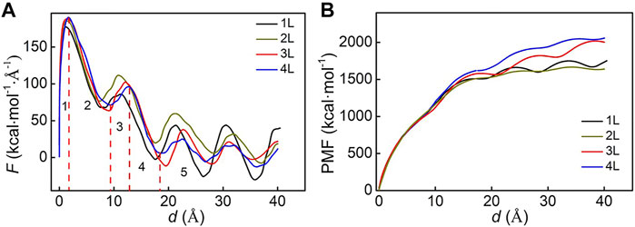
FIGURE 4. (A) Pulling force curves of the sandwiched systems with different layers of graphene. Different from the force curves without coating, these curves can be divided into five stages. When the force first reduces to the local minima, it follows by a small increment before decreasing to about zero. This small fluctuation is caused by the constraint release of the debonding between epoxy and graphene. (B) Corresponding PMF curves. The PMF reaches the local maxima when the force reduces to zero.
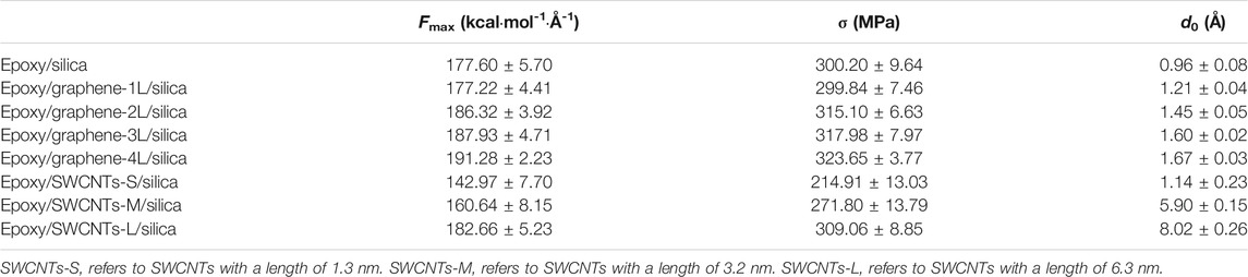
TABLE 1. Interfacial properties of different structures, including the maximum pulling force (Fmax), the adhesion stress (σ), and the corresponding displacement d0 at the point of Fmax.
Different from the force profile of the epoxy/silica system without coating, the force profile of the sandwiched systems with graphene coating can be divided into five stages. This is because, with the incorporation of graphene, there are two interfaces in the sandwiched structures. The variation of interfacial energy during the pulling process in the representative sandwiched structure with four layers of graphene is shown in Figures 5A and B, and the corresponding snapshots are shown in Figure 5C. The interaction between epoxy and graphene is reduced and converges to almost a stable value when the structure fails. The interaction between silica and graphene is reduced at the first stage but then increased with fluctuation at the second stage. This increment in the interfacial interaction is correlated with the constraint release. At this stage, the polymer chains of epoxy are debonded from the graphene as shown in Figure 5C, resulting in the constraint of graphene decreased. The constraint release promotes an improved interaction between graphene and silica. The increased interaction converges to a stable value from the third stage as the constraint effect can be negligible. When the sandwiched system with graphene coating fails, both the interfacial interactions keep a stable value. The interaction between graphene and epoxy still exists after the interface complete debonding. This means the failure of the graphene-coated silica/epoxy system occurs at the epoxy close to the interface instead of at the contact surface.
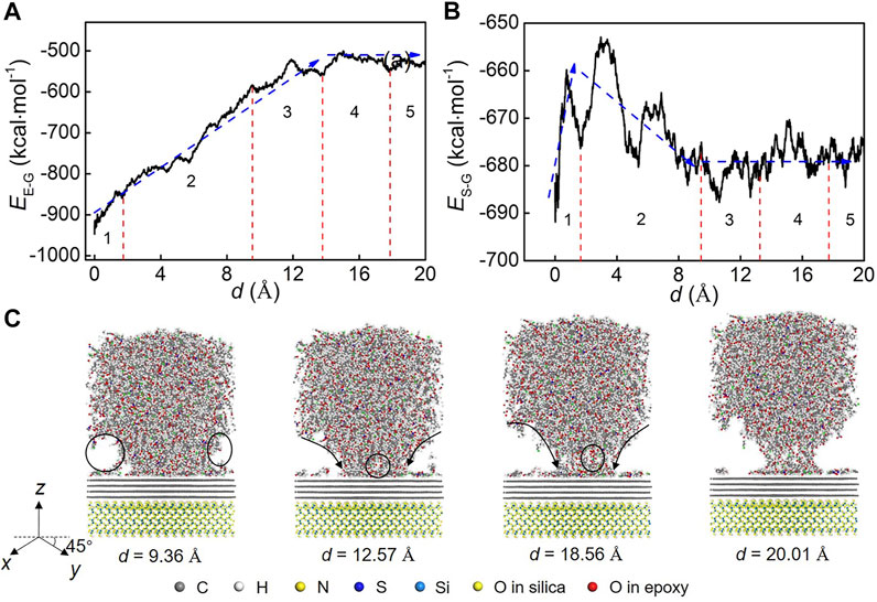
FIGURE 5. (A) Interfacial energy variation between epoxy and graphene during pulling for the sandwiched structure with four layers of graphene coating. EE-G refers to the interfacial energy between epoxy and graphene. (B) Interfacial energy variation between silica and graphene. ES-G refers to the interfacial energy between silica and graphene. (C) Interfacial structural evolution. The detachment first occurs at the edge of epoxy close to the interface. The detachment propagates into the inner and finally causes the debonding within the epoxy close to the interface.
The effect of SWCNTs on the adhesive stress is also shown in Table 1. It is found that when the silica is coated with short SWCNTs (∼1.3 nm), the adhesive stress is reduced. The longer the SWCNTs is, the higher the adhesive stress is. Similar to that of the sandwiched system with graphene coating, the pulling force curves can be divided into five stages. The pulling force profile and the conformational change in the representative system with the SWCNT length of 6.3 nm are shown in Figure 6. Some SWCNTs are first debonded from epoxy after the force reaches the first maxima, and then partial SWCNTs are debonded from silica with the force decreased to the local minima. The interfacial interactions between epoxy and SWCNTs and between silica and SWCNTs are reduced. The constraint release caused by the debonding between partial SWCNTs and silica leads to the structural rearrangement between silica and SWCNTs, causing an increment in the interfacial interaction between silica and SWCNTs. More force is required for the complete debonding between epoxy and silica. The displacement at the point of the second maxima of force is obviously higher than that in the structures with and without graphene coating. Finally, the interaction between silica and SWCNTs is reduced to around zero, while the interfacial interaction between epoxy and SWCNTs is stable. This means that the failure location of the interface in the sandwiched structures with SWCNTs coating is at the interface between silica and SWCNTs. The incorporation of SWCNTs restricts the movement of the molecular chain of the epoxy resin and also sets up bridging between the silica and the polymer matrix. This contributes to a significant improvement of the pulling displacement when the interface is completely debonded.
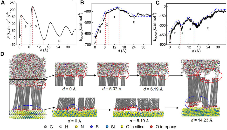
FIGURE 6. (A) Pulling force curve of the sandwiched structure with SWCNT coating. The length of SWCNTs is about 6.3 nm. After force is first reduced to the local minima (d = 6.19 Å), there is a rapid increment. This is because of the mechanical interlocking caused by SWCNTs. (B) Variation of interfacial energy between epoxy and SWCNTs. EE-CNT refers to the interfacial energy between epoxy and SWCNTs. (C) Variation of interfacial energy between silica and SWCNTs. ES-CNT refers to the interfacial energy between silica and SWCNTs. (D) Structural evolution of the interface in the sandwiched system. The interface fails at the point of force close to zero (d = 14.23 Å).
The mechanism of interfacial failure is varied when the carbon nanomaterials are coated on GF. First, the interfacial interactions are significantly improved with the incorporation of carbon nanomaterial on the surface of glass fiber. The interfacial energy of the equilibrated epoxy/silica structure is much lower than the interfacial energy in the sandwiched structures with graphene and CNT coatings indicating that the corporation of carbon nanomaterials can enhance the interfacial bonding energy. By comparing the role of graphene and SWCNTs on interfacial properties between epoxy and silica during debonding process, it is found that the graphene coating mainly contributes to the improvement of the adhesive stress, and SWCNTs can significantly enhance the pulling displacement before interface failure. The sandwiched structures with graphene and SWCNTs coatings represent different failure mechanisms, as shown in Figure 7. More specifically, the sandwiched structures with graphene coatings fail in the epoxy close to the interface, exhibiting a cohesive failure mode. However, for the sandwiched structure with SWCNTs, it fails at the interface between silica and SWCNTs, representing an adhesive failure mode. The interfacial interaction between silica and graphene is more stable than that between silica and SWCNTs at the initial equilibrated state because of ES-G < ES-CNT. This indicates, compared with GFR composites with SWCNTs coating, the failure of graphene-coated GFR epoxy is more likely to occur at the interface close to epoxy. Moreover, as the interlocking effect, partial SWCNTs can be still bonded to the polymer matrix whereas the van der Waals interactions that govern the interactions between SWCNTs and silica disappear with the increased pulling displacement. So, there is a relatively stronger interaction between graphene and silica in the graphene-coated silica/epoxy system and stronger interaction between epoxy and SWCNTs in CNT-coated silica/epoxy. A combined coating of graphene and CNTs can have a more effective role in improving the interfacial properties of GFR epoxy composites.
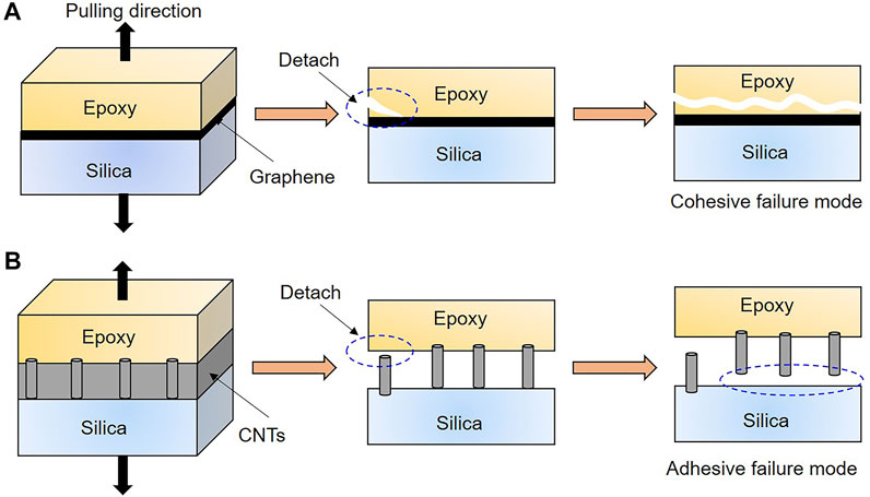
FIGURE 7. Mechanism of interface failure for the sandwiched structures with (A) graphene coating. The debonding initiates from the edge of epoxy close to the interface and propagates into the inner of epoxy. The graphene-coated GFR epoxy exhibits a cohesive failure mode. (B) CNTs coating. Although the debonding initiates between epoxy and CNTs, the interlocking between epoxy and CNTs prevents the further motion of polymer chains, resulting in that failure which occurs at the interface between silica and CNTs. The CNT-coated GFR epoxy displays an adhesive failure mode.
Our findings are comparable with experimental results and exhibit similar failure modes for different coatings. For example, it is found that the adhesion strength is improved with the graphene oxide coated on the GF and the failure of composites is at the graphene oxide/epoxy rather than at the graphene oxide/GF interface (Mahmood et al., 2016). During the pull-out test of a single CNT-coated fiber from the polymer matrix, the surface of the fiber is clean and completely devoid of traces of either CNTs or polymer, indicating the failure occurs at the interface between fiber and CNTs (Agnihotri et al., 2011; Agnihotri et al., 2012). Experiments have also revealed that graphene has a better effect on the improvement of interfacial strength than CNTs (Zeng et al., 2018). The combined effect of carbon nanomaterials on the interfacial properties has also been investigated (Hua et al., 2017). The interfacial bond strength of GFR composite with the graphene oxide and CNT hybrid coating layer is much higher than that with only CNT coating or graphene oxide coating. The graphene and CNTs can significantly affect the interfacial failure mechanism which is consistent with our simulation findings. However, the interfacial properties such as the maximum pulling force and the adhesion stress predicted in our work are much higher than that tested by experiments. This is because the presence of CNT agglomerates and stacked graphene deteriorates their strengthened role, which are not considered in our work. Additionally, our studies provide a guideline for the structure design of graphene and CNTs to optimize the mechanical properties of coated GFR composites. As the single component, graphene and CNTs have certain limited improvement; nowadays, the surface modification of graphene and CNTs hybrid has attracted tremendous interest for the optimum properties of composites. The revealed interfacial failure mechanism in this work can lay a theoretical foundation for optimal performance of carbon nanomaterial-coated GFR composites.
In this work, the interfacial behavior of the carbon nanomaterial–coated GFR epoxy has been studied, and steered molecular dynamics simulations have been conducted to explore the mechanism of interfacial failure with and without coatings on GF. The effect of the thickness of graphene and the length of SWCNTs on the interfacial properties such as the force for debonding, the corresponding displacement, and the adhesion stress has been investigated. Several interesting findings are revealed below.
1) The adhesion stress of the sandwiched structures with graphene coatings is increased with the increment of graphene layers. The positive effect on the adhesion stress is similar when the thickness of graphene is more than two layers, whereas the pulling displacement for debonding is significantly increased with the increment of graphene thickness. Graphene has a better effect on improving the adhesion stress compared with SWCNTs.
2) Both the adhesion stress and the corresponding displacement is increased with the increment of SWCNT length. Compared with the graphene coating, SWCNTs have a more obvious enhancement effect on the displacement for debonding.
3) The sandwiched structures with graphene coatings fail in the epoxy close to the interface, representing a cohesive failure mode; while the structures with SWCNTs fail at the contact surface between silica and SWCNTs, displaying an adhesion failure mode.
4) As the interfacial interaction between epoxy and SWCNTs is comparable to that between SWCNTs and silica, the mechanical interlocking of SWCNTs restricts the movement of the molecular chain of the epoxy resin, causing the force response and the interfacial failure mode of the SWCNTs coated silica/epoxy systems during pulling different from those of the graphene coated systems.
As a summary, this work reveals the mechanism of interfacial failure with different carbon nanomaterials coated on GF. The underlying reason for the improvement in the interfacial adhesion of graphene- and CNT-coated GFR epoxy composites is understood. Our findings enable us to figure out the different mechanical responses of graphene- or CNT-coated GFR polymer composites. The revealed interfacial failure mechanism in this work can lay a theoretical foundation for structure design and the surface modification of carbon nanomaterial coatings incorporated in GFR composites.
The original contributions presented in the study are included in the article/Supplementary Material; further inquiries can be directed to the corresponding author.
YS contributes to the design and implementation of the research. ZL contributes to the model design. JD contributes to the model validation. ZX contributes to the debonding simulations. YN contributes to validation. YC contributes to the data analysis. BY contributes to the draft review. HH contributes to supervision, conceptualization, and writing.
The authors would like to acknowledge the supporting given by the Key R and D Project of Hubei Province: Research on Key Technologies of UHV Power Transformer Resin-covered Film Bushing. They also acknowledge the research funding from Wuhan University (Project Number: 413100074) and the Natural Science Foundation of Huber Province (2021CFB137). The numerical calculations in this article have been done on the supercomputing system in the Supercomputing Center of Wuhan University.
YS, ZL, JD, ZX, and YN are employed by the State Grid Electric Power Research Institute, Wuhan, China.
The remaining authors declare that the research was conducted in the absence of any commercial or financial relationships that could be construed as a potential conflict of interest.
All claims expressed in this article are solely those of the authors and do not necessarily represent those of their affiliated organizations, or those of the publisher, the editors, and the reviewers. Any product that may be evaluated in this article, or claim that may be made by its manufacturer, is not guaranteed or endorsed by the publisher.
Agnihotri, P., Basu, S., and Kar, K. K. (2011). Effect of Carbon Nanotube Length and Density on the Properties of Carbon Nanotube-Coated Carbon Fiber/polyester Composites. Carbon 49, 3098–3106. doi:10.1016/j.carbon.2011.03.032
Agnihotri, P. K., Kar, K. K., and Basu, S. (2012). Cohesive Zone Model of Carbon Nanotube-Coated Carbon Fiber/polyester Composites. Model. Simul. Mater. Sci. Eng. 20, 035014. doi:10.1088/0965-0393/20/3/035014
Amariutei, O. A., Ramsdale-Capper, R., Correa Álvarez, M., Chan, L. K. Y., and Foreman, J. P. (2018). Modelling the Properties of a Difunctional Epoxy Resin Cured with Aromatic Diamine Isomers. Polymer 156, 203–213. doi:10.1016/j.polymer.2018.10.016
Dastorian Jamnani, B., Hosseini, S., Rahmanian, S., Abdul Rashid, S., Mustapha, S. a. b., and Keshan Balavandy, S. (2015). Grafting Carbon Nanotubes on Glass Fiber by Dip Coating Technique to Enhance Tensile and Interfacial Shear Strength. J. Nanomater. 2015, 1–7. doi:10.1155/2015/149736
Dewapriya, M. A. N., and Meguid, S. A. (2019). Comprehensive Molecular Dynamics Studies of the Ballistic Resistance of Multilayer Graphene-Polymer Composite. Comput. Mater. Sci. 170, 109171. doi:10.1016/j.commatsci.2019.109171
Fan, H. B., and Yuen, M. M. F. (2007). Material Properties of the Cross-Linked Epoxy Resin Compound Predicted by Molecular Dynamics Simulation. Polymer 48, 2174–2178. doi:10.1016/j.polymer.2007.02.007
Fu, K., Xie, Q., Lü, F., Duan, Q., Wang, X., Zhu, Q., et al. (2019). Molecular Dynamics Simulation and Experimental Studies on the Thermomechanical Properties of Epoxy Resin with Different Anhydride Curing Agents. Polymers 11, 975. doi:10.3390/polym11060975
Hao, H., Chow, C. L., and Lau, D. (2020a). Carbon Monoxide Release Mechanism in Cellulose Combustion Using Reactive Forcefield. Fuel 269, 117422. doi:10.1016/j.fuel.2020.117422
Hao, H., Hui, D., and Lau, D. (2020b). Material Advancement in Technological Development for the 5G Wireless Communications. Nanotechnol Rev. 9, 683–699. doi:10.1515/ntrev-2020-0054
Hao, H., and Lau, D. (2017). Atomistic Modeling of Metallic Thin Films by Modified Embedded Atom Method. Appl. Surf. Sci. 422, 1139–1146. doi:10.1016/j.apsusc.2017.05.011
Hao, H., Tam, L.-h., Lu, Y., and Lau, D. (2018). An Atomistic Study on the Mechanical Behavior of Bamboo Cell wall Constituents. Composites B: Eng. 151, 222–231. doi:10.1016/j.compositesb.2018.05.046
Hao, H., Zhou, W., Lu, Y., and Lau, D. (2019). Atomic Arrangement in CuZr-Based Metallic Glass Composites under Tensile Deformation. Phys. Chem. Chem. Phys. 22, 313–324. doi:10.1039/c9cp04914b
Hu, Z., Zhang, D., Lu, F., Yuan, W., Xu, X., Zhang, Q., et al. (2018). Multistimuli-responsive Intrinsic Self-Healing Epoxy Resin Constructed by Host-Guest Interactions. Macromolecules 51, 5294–5303. doi:10.1021/acs.macromol.8b01124
Hua, Y., Li, F., Liu, Y., Huang, G.-W., Xiao, H.-M., Li, Y.-Q., et al. (2017). Positive Synergistic Effect of Graphene Oxide/carbon Nanotube Hybrid Coating on Glass Fiber/epoxy Interfacial normal Bond Strength. Composites Sci. Technology 149, 294–304. doi:10.1016/j.compscitech.2017.06.024
Jin, K., Luo, H., Wang, Z., Wang, H., and Tao, J. (2020). Composition Optimization of a High-Performance Epoxy Resin Based on Molecular Dynamics and Machine Learning. Mater. Des. 194, 108932. doi:10.1016/j.matdes.2020.108932
Kamar, N. T., Hossain, M. M., Khomenko, A., Haq, M., Drzal, L. T., and Loos, A. (2015). Interlaminar Reinforcement of Glass Fiber/epoxy Composites with Graphene Nanoplatelets. Composites A: Appl. Sci. Manufacturing 70, 82–92. doi:10.1016/j.compositesa.2014.12.010
Leroch, S., and Wendland, M. (2012). Simulation of Forces between Humid Amorphous Silica Surfaces: A Comparison of Empirical Atomistic Force fields. J. Phys. Chem. C 116, 26247–26261. doi:10.1021/jp302428b
Li, C., Browning, A. R., Christensen, S., and Strachan, A. (2012). Atomistic Simulations on Multilayer Graphene Reinforced Epoxy Composites. Composites Part A: Appl. Sci. Manufacturing 43, 1293–1300. doi:10.1016/j.compositesa.2012.02.015
Li, Y., Wang, Q., and Wang, S. (2019). A Review on Enhancement of Mechanical and Tribological Properties of Polymer Composites Reinforced by Carbon Nanotubes and Graphene Sheet: Molecular Dynamics Simulations. Composites Part B: Eng. 160, 348–361. doi:10.1016/j.compositesb.2018.12.026
Ma, H., Zhang, X., Ju, F., and Tsai, S.-B. (2018). A Study on Curing Kinetics of Nano-phase Modified Epoxy Resin. Sci. Rep. 8, 3045. doi:10.1038/s41598-018-21208-0
Mahmood, H., Tripathi, M., Pugno, N., and Pegoretti, A. (2016). Enhancement of Interfacial Adhesion in Glass Fiber/epoxy Composites by Electrophoretic Deposition of Graphene Oxide on Glass Fibers. Composites Sci. Technology 126, 149–157. doi:10.1016/j.compscitech.2016.02.016
Mohan, P. (2013). A Critical Review: The Modification, Properties, and Applications of Epoxy Resins. Polymer-Plastics Technology Eng. 52, 107–125. doi:10.1080/03602559.2012.727057
Moller, J. C., Berry, R. J., and Foster, H. A. (2020). On the Nature of Epoxy Resin post-curing. Polymers 12, 466. doi:10.3390/polym12020466
Park, C., Jung, J., and Yun, G. J. (2019). Thermomechanical Properties of Mineralized Nitrogen-Doped Carbon Nanotube/polymer Nanocomposites by Molecular Dynamics Simulations. Composites Part B: Eng. 161, 639–650. doi:10.1016/j.compositesb.2019.01.002
Plimpton, S. (1995). Fast Parallel Algorithms for Short-Range Molecular Dynamics. J. Comput. Phys. 117, 1–19. doi:10.1006/jcph.1995.1039
Pramanik, C., Nepal, D., Nathanson, M., Gissinger, J. R., Garley, A., Berry, R. J., et al. (2018). Molecular Engineering of Interphases in Polymer/carbon Nanotube Composites to Reach the Limits of Mechanical Performance. Composites Sci. Technology 166, 86–94. doi:10.1016/j.compscitech.2018.04.013
Rahaman, A., and Kar, K. K. (2014). Carbon Nanomaterials Grown on E-Glass Fibers and Their Application in Composite. Composites Sci. Technology 101, 1–10. doi:10.1016/j.compscitech.2014.06.019
Rahmanian, S., Suraya, A. R., Zahari, R., and Zainudin, E. S. (2013). Synthesis of Vertically Aligned Carbon Nanotubes on Carbon Fiber. Appl. Surf. Sci. 271, 424–428. doi:10.1016/j.apsusc.2013.01.207
Ren, D., Li, K., Chen, L., Chen, S., Han, M., Xu, M., et al. (2019). Modification on Glass Fiber Surface and Their Improved Properties of Fiber-Reinforced Composites via Enhanced Interfacial Properties. Composites Part B: Eng. 177, 107419. doi:10.1016/j.compositesb.2019.107419
Réquilé, S., Le Duigou, A., Bourmaud, A., and Baley, C. (2019). Interfacial Properties of Hemp Fiber/epoxy System Measured by Microdroplet Test: Effect of Relative Humidity. Composites Sci. Technology 181, 107694. doi:10.1016/j.compscitech.2019.107694
Shin, P.-S., Kwon, D.-J., Kim, J.-H., Lee, S.-I., DeVries, K. L., and Park, J.-M. (2017). Interfacial Properties and Water Resistance of Epoxy and CNT-Epoxy Adhesives on GFRP Composites. Composites Sci. Technology 142, 98–106. doi:10.1016/j.compscitech.2017.01.026
Stoffels, M. T., Staiger, M. P., and Bishop, C. M. (2019). Reduced Interfacial Adhesion in Glass Fibre-Epoxy Composites Due to Water Absorption via Molecular Dynamics Simulations. Composites Part A: Appl. Sci. Manufacturing 118, 99–105. doi:10.1016/j.compositesa.2018.12.018
Sun, Q., Zhao, Y., Choi, K.-S., Hou, X., and Mao, X. (2021). Reduction of Atomistic Ice Tensile Stress by Graphene-Carbon Nanotube Coating. Appl. Surf. Sci. 565, 150562. doi:10.1016/j.apsusc.2021.150562
Sun, S., Chen, S., Weng, X., Shan, F., and Hu, S. (2019). Effect of Carbon Nanotube Addition on the Interfacial Adhesion between Graphene and Epoxy: A Molecular Dynamics Simulation. Polymers 11, 121. doi:10.3390/polym11010121
Xie, Q., Fu, K., Liang, S., Liu, B., Lu, L., Yang, X., et al. (2018). Micro-structure and Thermomechanical Properties of Crosslinked Epoxy Composite Modified by Nano-SiO2: A Molecular Dynamics Simulation. Polymers 10, 801. doi:10.3390/polym10070801
Yao, X., Gao, X., Jiang, J., Xu, C., Deng, C., and Wang, J. (2018). Comparison of Carbon Nanotubes and Graphene Oxide Coated Carbon Fiber for Improving the Interfacial Properties of Carbon Fiber/epoxy Composites. Composites Part B: Eng. 132, 170–177. doi:10.1016/j.compositesb.2017.09.012
Yuan, J.-M., Fan, Z.-F., Yang, Q.-C., Li, W., and Wu, Z.-J. (2018). Surface Modification of Carbon Fibers by Microwave Etching for Epoxy Resin Composite. Composites Sci. Technology 164, 222–228. doi:10.1016/j.compscitech.2018.05.043
Zeng, S., Shen, M., Chen, S., Yang, L., Lu, F., and Xue, Y. (2018). Mechanical and thermal Properties of Carbon Nanotube- and Graphene-Glass Fiber Fabric-Reinforced Epoxy Composites: A Comparative Study. Textile Res. J. 89, 2353–2363. doi:10.1177/0040517518792750
Zhang, H.-p., Han, W., Tavakoli, J., Zhang, Y.-p., Lin, X., Lu, X., et al. (2019). Understanding Interfacial Interactions of Polydopamine and Glass Fiber and Their Enhancement Mechanisms in Epoxy-Based Laminates. Composites Part A: Appl. Sci. Manufacturing 116, 62–71. doi:10.1016/j.compositesa.2018.10.024
Keywords: interfacial properties, glass fiber–reinforced epoxy composite, steered molecular dynamics, graphene, carbon nanotube, failure mode
Citation: Song Y, Lan Z, Deng J, Xu Z, Nie Y, Chen Y, Yang B and Hao H (2022) Enhanced Interfacial Properties of Carbon Nanomaterial–Coated Glass Fiber–Reinforced Epoxy Composite: A Molecular Dynamics Study. Front. Mater. 8:828001. doi: 10.3389/fmats.2021.828001
Received: 02 December 2021; Accepted: 10 December 2021;
Published: 12 January 2022.
Edited by:
Lik-ho Tam, Beihang University, ChinaReviewed by:
Chi Zhang, ETH Zürich, SwitzerlandCopyright © 2022 Song, Lan, Deng, Xu, Nie, Chen, Yang and Hao. This is an open-access article distributed under the terms of the Creative Commons Attribution License (CC BY). The use, distribution or reproduction in other forums is permitted, provided the original author(s) and the copyright owner(s) are credited and that the original publication in this journal is cited, in accordance with accepted academic practice. No use, distribution or reproduction is permitted which does not comply with these terms.
*Correspondence: Huali Hao, aHVhbGloYW8zLWNAbXkuY2l0eXUuZWR1Lmhr
Disclaimer: All claims expressed in this article are solely those of the authors and do not necessarily represent those of their affiliated organizations, or those of the publisher, the editors and the reviewers. Any product that may be evaluated in this article or claim that may be made by its manufacturer is not guaranteed or endorsed by the publisher.
Research integrity at Frontiers
Learn more about the work of our research integrity team to safeguard the quality of each article we publish.