 Feng Qin
 Chunbo Zhang1,2
95% of researchers rate our articles as excellent or good
Learn more about the work of our research integrity team to safeguard the quality of each article we publish.
Find out more
ORIGINAL RESEARCH article
Front. Mater. , 05 January 2022
Sec. Structural Materials
Volume 8 - 2021 | https://doi.org/10.3389/fmats.2021.813118
This article is part of the Research Topic Joining and Welding of New and Dissimilar Materials View all 7 articles
In recent years, studying the weldability of a dissimilar metal hybrid structure, with the potential to make full use of their unique benefits, has been a research hotspot. In this article, inertia friction welding was utilized to join Φ130 forged ring of 2219 aluminum alloy with 304 stainless steel. Optical observation (OM), electron back scattering diffraction (EBSD), and scanning electron microscopy (SEM) were utilized to examine the joint microstructure in depth. Depending on the research, a significant thermal–mechanical coupling effect occurs during welding, resulting in inadequate recrystallization on aluminum-side thermo-mechanically affected zone (TMAZ) and forming zonal features. The crystal orientation and grain size of each TMAZ region reflect distinct differences. On the joint faying surface, the growth of intermetallic compounds (IMCs) is inhibited by a fast cooling rate and metallurgical bonding characteristics were found depending on the discontinuous distribution of IMCs. The average joint tensile strength can reach 161.3 MPa achieving 92.2% of 2219-O; fracture occurs on aluminum-side base metal presenting ductile fracture characteristics.
The lightness of aluminum and the high strength of steel could be fully exploited in hybrid aluminum/steel construction, lowering structural weight and manufacturing costs while maintaining component service performance. Nowadays, demand for aluminum/steel hybrid components with solid or tubular sections is increasing in many engineering fields, such as refrigeration industry, air separation equipment manufacturing, and aerospace engine manufacturing.
Obtaining sound dissimilar metal joints depends on the differences in metallurgical compatibility and thermophysical properties of base metals. Besides, the compatibility of the welding method to joint shape is also important. For fusion and brazing joint of aluminum to steel, massive metallurgical incompatibility and thermophysical differences between aluminum and steel cause a high number of brittle intermetallic compounds (IMCs) to develop which always reduce the joint strength. Rotary friction welding, as opposed to fusion and brazing welding, is better for welding aluminum/steel rotating workpieces such as circular rods and pipes. Continuous drive friction welding (CDFW) and inertia friction welding (IFW) are the two primary types of rotary friction welding; the most significant distinction between these two processes is the mode of providing energy to the welding interface (Li et al., 2016). In the CDFW process, the motor drags the spindle clutching workpiece to a specified speed and provides continuous energy, while in IFW the motor first drags the flywheel clamping workpiece to the specified speed and the flywheel disengages from the motor, then the rotational kinetic energy of flywheel is used to provide friction heat.
In recent decades, scholars using small-diameters rods have conducted detailed studies on welding parameters (Fukumoto et al., 1997; Fuji 2004; Kimura et al., 2009; Kimura et al., 2017), IMC distribution and compositional characteristics (Fukumoto et al., 2000; Sahin 2014; Liu Y. et al., 2019; Dong et al., 2019; Wang et al., 2020), microstructure characteristics of aluminum-side TMAZ (thermo-mechanically affected zone) (Wan and Huang 2018; Liu, Zhao, and Peng 2020), corrosion behavior (Ma et al., 2021), and residual stress distribution (Gan et al., 2016) of the aluminum/steel joint welded by CDFW, aiming to achieve high joint efficiency close to the aluminum side as much as possible. However, it was discovered that in order to obtain sound joints, strict controlling of welding parameters or introducing additional processes is also required; otherwise, the brittle IMCs reducing joint strength remains a serious problem.
In addition to conventional research, multiple studies on alternative approaches to enhance joint strength have been done. Firstly, different heat treatment methods can improve joint performance: the IMC interlayer at the welding interface that was formed during the PWHT (post-weld heat treatment) process affected the fractured location of the joint between AA6063 and 304SS (Kimura et al., 2020);the growth rate of IMCs at various joint radii with different heat treatment sensitivities (Dong et al., 2020); and 1,000°C preheating with argon protection which could prevent porous oxide formation at the Fe/Al joint interface (Yılmaz et al., 2002). Proper selection of solution and aging treatment parameters can improve AW6082/20MnCr5 joint strength while preventing the growth of IMCs (Herbst et al., 2017). Secondly, tapered and polished steel faying surface design might extrude impurities and IMCs out of the faying surface with flash, minimizing friction heat production and preventing IMC development (Ashfaq et al., 2013; Pinheiro and Bracarense 2019). Moreover, the ductile Ag plated on the stainless steel side before welding can reduce the friction coefficient and prevent the generation of thick IMCs resulting from overheating, while the Ag interlayer also acts as a barrier to effectively inhibit the diffusion process from Fe to Al and prevent the IMCs evolving into an “Al-rich” phase (Reddy, Rao, and Mohandas 2008). When using CDFW to weld aluminum MMCs and AISI 304, the Ag interlayer could reduce the particle fragmentation ratio and the width of the softening zone on the aluminum side (Kannan et al., 2015).
Compared to CDFW, IFWs have unique benefits when welding aluminum to steel. The properties and microstructural characterization on 6061-T6 aluminum to AISI 1018 steel joint with a 12.5-mm diameter welded by IFWs explained that the bond lines could achieve a thin layer of IMCs (Taban, Gould, and Lippold 2010). Mechanical properties of the 6061-T6/SS304 IFW joint with a 15-mm diameter was investigated, and the tensile strength of the joint reached to the maximum tensile strength of 323 MPa, which was about 94% of Al 6061 (Liu Yong et al., 2019).
Majority of earlier research concentrated on employing small-diameter rods and mainly used CDFW to weld aluminum to steel. There have been few investigations regarding IFWs of aluminum to steel, particularly for large-diameter workpieces. In this research, IFW was used to join 2219-O aluminum alloy and 304 stainless steel. Optical observation (OM), electron backscattering diffraction (EBSD), and scanning electron microscope (SEM) were used to investigate the joint near-faying surface and interface microstructure. The tensile test and microhardness were examined. This study provides theoretical and technical support for the use of inertial friction welding technology and facilitates the construction of a dissimilar material welding theory system.
A 2219 forging ring was used in this experiment with O state which has excellent shaping and machining properties and in accordance with the liquid oxygen delivery pipe. The stainless steel forging ring is S30408. The chemical composition and mechanical properties are listed in Tables 1, 2. Both faying surfaces of the workpieces are machined into conical to limit the heat input and enhance the effective flow of IMCs.

TABLE 1. Chemical composition and mechanical properties of 2219-O.

TABLE 2. Chemical composition and mechanical properties of S30408.
A circular mold was mounted on the outer edge of the 2219 forging ring controlling flash generation to reduce material and heat loss caused by significant deformation of 2219 during the upsetting process. The stainless steel was put on the rotating part of the 2219 since the circular mold was prone to falling off when spinning. The workpiece sketch map is shown in Figure 1.
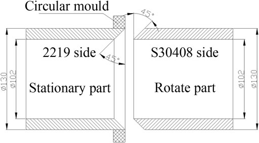
FIGURE 1. Sketch map of the workpiece before welding (unit: mm).
An HWI-GXH-130 inertia friction welding machine was used with 1,300 kN maximum welding force, 1,000 rpm maximum spindle speed, and 380 kg m2 maximum rotational inertia. The welding parameter incorporated rotary inertia of 155 kg m2; rotational speeds of 300 rpm; upsetting pressure of 170 MPa; and upsetting time of 10 s.
The sample cutting position and size are shown in Figure 2; two 2-mm-thickness specimens were prepared by wire-electrode cutting for microstructure observation in different methods. Due to the difficulty of etching aluminum and stainless steel simultaneously for OM, one specimen was split into two pieces at the interface with hand pliers in which the etching process was carried out respectively. The 2219 specimen was ground to 2,000 with abrasive paper and polished, then Keller’s reagent (1.5 ml HCL +1 ml HF+2.5 ml HNO3+95 ml H2O) was used to etch. The stainless steel specimen was electrolytically corroded in 10% oxalic acid solution by 30 V and corrosion time of 15 s. All optical specimens were observed under an Axiovert 40 MAT metallographic microscope.
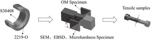
FIGURE 2. Test sample size and location (unit: mm).
In this study, SEM and EBSD analyses were carried out on TESCAN MAIA3 SEM aiming to study the interface microstructure and detailed near-interface crystal orientation. The sample was vibratorily polished to remove remaining deformations, and a step size of 2 μm was used for EBSD analysis.
An EBSD orientational structure discussion was based on the sample primary coordinate system. Figure 3 shows the relationship between the acquisition surface coordinate system (X1,Y1,Z1) and sample primary coordinate system (X0,Y0,Z0). The Y0 direction is parallel to the faying interface forming an angle of 45° with a tilt axis, and X0 is the normal direction aligning the faying surface.
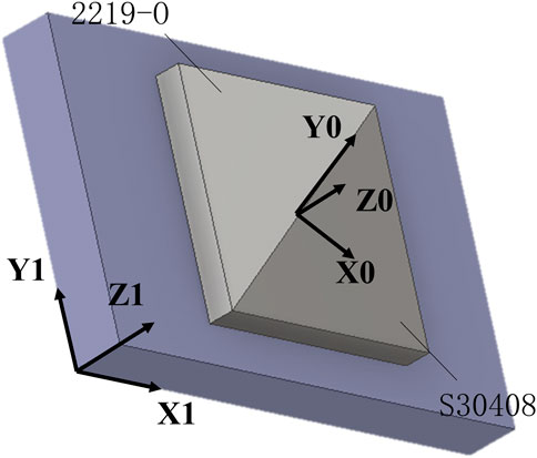
FIGURE 3. The coordinate system of EBSD testing.
A Vickers microhardness test perpendicular to the faying interface was carried out. The loading force was 1.961 N, and the pressure was kept for 10 s. A three-times tensile test was performed using an Instron 5582 universal testing machine at a loading rate of 0.1 mm/min, with the size of the tensile sample given in Figure 4. The final tensile strength value is obtained from the average of all three specimens.
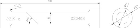
FIGURE 4. Size of tensile specimen (unit: mm).
Figure 5 illustrates the morphology of the aluminum side near-interface optical microstructure and the aluminum side equiaxed grain region with a width of 1.13 mm which is the outcome of the dynamic recrystallization process in TMAZ. The region can be further separated into coarse- and fine-grained zones by a black forging line.
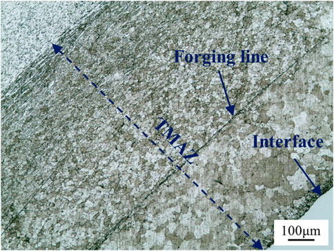
FIGURE 5. Near interface 2219-O macrostructure morphology.
Because the distance from the welding interface influences the degree of friction-thermodynamic coupling, the closer zone with coarse grain acquiring more friction heat had experienced an overheated recrystallization process. Further zones have a superior heat dissipation condition and a faster cooling rate, so the grains were refined.
A near-interface stainless steel optical microstructure is shown in Figure 6. Compared with aluminum alloy, the near interface grain of stainless steel has no obvious change, presenting uniformly equiaxed grain morphology.
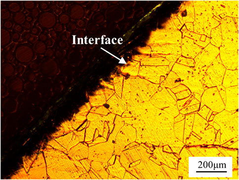
FIGURE 6. Near interface 30408 macrostructure morphology.
In Figure 7, a near interface grain boundary distribution map is exhibited. In order to distinguish different phases, aluminum and austenitic phases were represented as red and green, respectively.
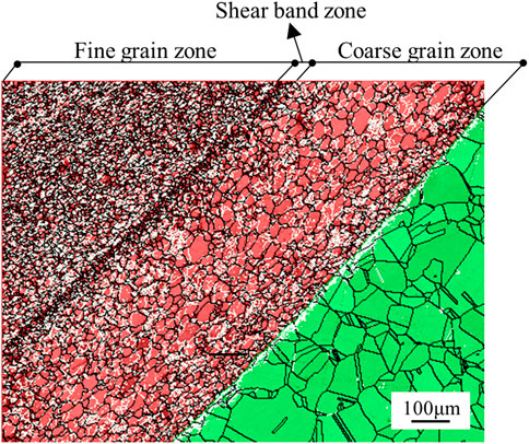
FIGURE 7. Stacking map of phases and grain boundaries.
In comparison to Figure 5, the grain size distribution of different locations in Figure 7 can be seen more clearly than on the OM map, and a thin ultra-fine grain band around the forging line can be identified at the same time. Eventually, the aluminum side TMAZ could be separated into fine grain zone (FDZ), shear band zone (SBZ), and coarse grain zone (CGZ) based on the grain size of each region. The average grain diameter statistics for each zone are shown in Figure 8; SBZ has the smallest grain with a mean size of 13.1 μm and the lowest discrete degree as compared to the CGZ which has achieved considerable inhomogeneous grain size.
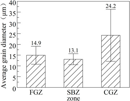
FIGURE 8. Average grain diameter of each zone on the aluminum side.
The grain boundary angle distribution is utilized to investigate the recrystallization process during and after welding. Low-angle grain (2°∼15°) boundaries (LABs) are emphasized by white lines in Figure 7, whereas high-angle grain boundaries (>15°) are depicted by black lines. Combined with the boundary statistics results in Figure 9, it can be seen that the LABs in FGZ account for the largest proportion at 29%. This reveals that in FGZ, after dynamic recovery, the subsequent dynamic recrystallization process was incomplete, which slowed the grain boundary migration process.
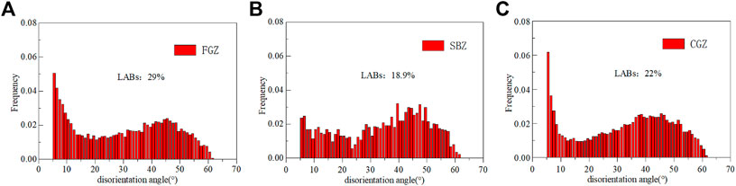
FIGURE 9. Average grain diameter on the aluminum side. (A) FGZ, (B) SBZ, (C) CGZ.
Meanwhile, the LAB percentage of SBZ was only 18.9%. SBZ has the smallest grain size and lowest percentage of LABs. It is possible that the flowing plastic aluminum during the forge process took most of the friction heat away and facilitated the cooling process. White grain boundaries representing LABs can also be observed in the 304 side adjacent to the welding interface; this is because the friction torque results in the formation of substructures.
The grain reference orientation deviation (GROD) angle map layer aids in the visualization of sample substructures. It is very effective for identifying deformation in grains that have even the smallest misorientation angle pixel by pixel. The GROD angle map is shown in Figure 10. In comparison to the FGZ and CGZ, the SBZ clearly had fewer substructures on the aluminum side. It is also worth noting that a row of austenitic grains close to the interface exhibits substantial angular variation inside the grain.
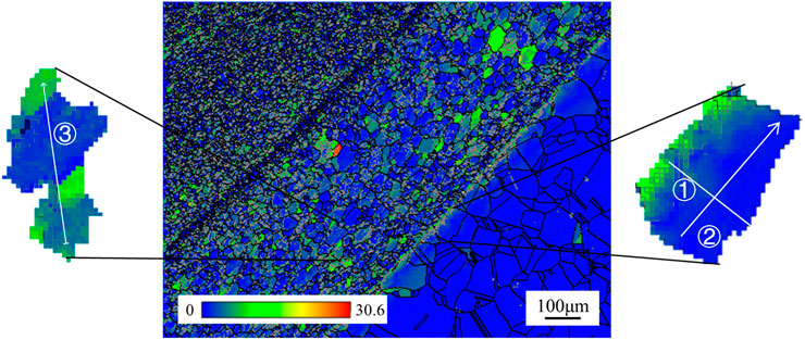
FIGURE 10. GROD angle map with location of grain disorientation measurement lines.
In order to further analyze variations of orientation within different grains, disorientation characterizations along measurement lines through grains in different directions were further elucidated as shown in Figure 10 using three different lines. The chosen austenitic grain adjacent to the welding interface is crossed by lines ① and ② which are vertical, and the cumulative misorientation profile of line ①(Figure 11A) shows a sharp jump from the original point to 8 μm with a 7° angular variation. This orientation change is mostly caused by forge pressure at the ending of the welding process, although it has a limited influence on stainless steel. By contrast, the point-to-point and cumulative disorientation of line ② (Figure 11B) only exhibited a reciprocating change less than 3°; this revealed that no obvious grain torsion occurred far away from the interface. On the other side, in Figure 11C, the cumulative disorientation profile of aluminum grain (line ③) displays a double-peak feature which can prove that this grain underwent torsional deformation. This result demonstrates that subgrains created within aluminum grains can occur from extreme compressive deformation caused by a large forging impact and that each subgrain part has a different orientation.
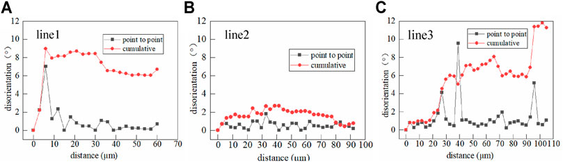
FIGURE 11. Disorientation profiles along line 1 (A), line 2 (B), and line 3 (C).
The severe thermal–mechanical coupling effect during the forge process also resulted in preferential orientation on the aluminum side. For the FGZ, SBZ, and CGZ, their pole figures are calculated and listed in Figure 12; the theoretical texture components are listed in Figure 12D. In FGZ, the microstructure clearly exhibits a strong {110} <100> feature which is Goss textures, whereas in SBZ and CGZ, the <100> crystal orientation of major aluminum grains is approximate parallel to Z0.
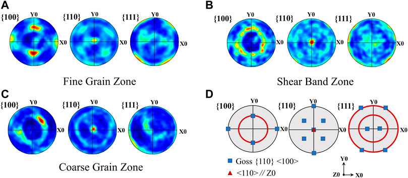
FIGURE 12. Pole figures of aluminum side on the X0–Y0 plane: (A) fine grain zone, (B) shear band zone, (C) coarse grain zone, (D) theoretical pole figures of gross and fiber texture.
Figure 13 depicts the microstructure of the faying surface at different magnifications. The 2219 aluminum in the upper left corner is shown in black, and the 304 stainless steel in the bottom right is shown in white, while the IMCs is shown in gray in the middle.
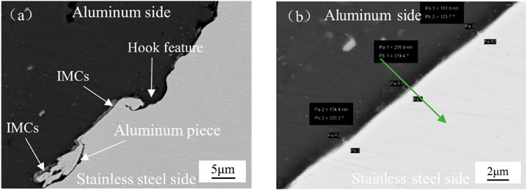
FIGURE 13. Interface SEM micrographs of welding joint in different scales:(A) ×2,000 magnification. (B) ×1,000 magnification.
Under ×2,000 magnification (Figure 13A), the faying surface presents uneven and hook features. Simultaneously, the IMCs less than 1 μm display a discontinuous distribution. More especially, parts of aluminum pieces affected by friction effect had rolled into the stainless steel side. The above characteristics illustrate that shear friction force along the inclined plane led to the formation of the hook feature, also promoting IMC fragmentation and subsequent expulsion into flash.
Under ×1,000 magnification (Figure 13B), the average thickness of IMCs determined at three different locations is only 0.18 μm.
The energy-dispersive spectrometer line scanning results (Figure 14) demonstrate that the principal elements performed solid-state interdiffusion, with Al having a diffusion distance of approximately 6.49 μm compared to Fe of 6.14 μm. This type of diffusivity variation is caused mostly by atomic radius dissimilarity in element variety. The IMCs on the “Al-rich” side are so thin (0.18 μm) that it is difficult to distinguish the composition and percentage of certain elements using solely EDS results since there is no plateau in diffusion curves. Because of the incredibly short cooling time of inertial friction welding, the interdiffusion capacities of materials in solid state are limited.
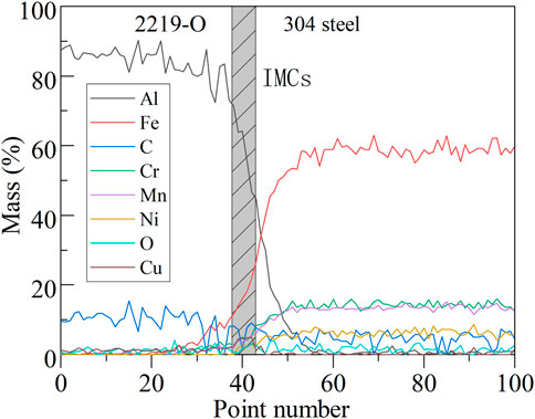
FIGURE 14. EDS linescan of the compositional gradient across the interface.
Microhardness, an important evaluating index of mechanical property, reacts to the ability resisting to local deformation of material (Huang et al., 2018). Figure 15 shows examples of Vickers hardness distributions across the welding interface. It is obvious that there exists a hardness increasing area on the aluminum side adjacent to the welding interface and the width is perfectly consistent with TMAZ. In this area, except the abnormal low microhardness point in SBZ, the microhardness value is ascended with increasing distance from the faying surface and subsequently drops sharply to the normal value of the base metal. Because 2219-O is under full annealing state disabling precipitation strengthening of θ(CuAl2), the microhardness of aluminum base metal is only 50 HV. During the forging process, strong compressive deformation of softened aluminum caused work hardening and subsequent fast cooling speed, retarding the recrystallization process. Additionally, the severe plastic deformation also refines the grain size and then increases the microhardness according to the Hall–Petch relation (Meng et al., 2021).
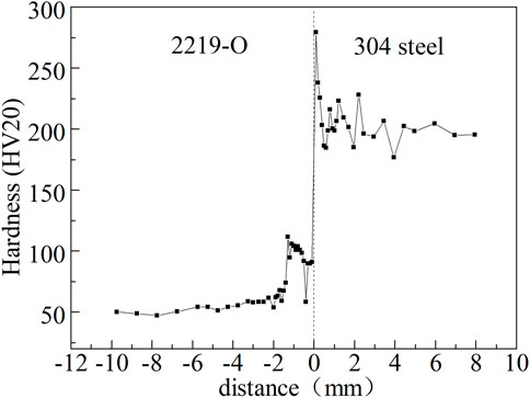
FIGURE 15. Vickers hardness distributions across welding interface.
In comparison, the stainless steel microhardness at the welding interface rose, reaching 279 HV, but as the measurement point moved away from the interface, the microhardness value abruptly fell. This phenomenon is most likely owing to residual compressive stress on the stainless steel side (Gan et al., 2016).
Tensile fracture can generally indicate joint ductility for dissimilar metal welding. The fracture points of three tensile specimens were depicted in Figure 16, which all occurs on the aluminum side and approximately 10 mm from the faying surface center. With a 19% average reduction in area, distinct plastic fracture characteristics can be seen, demonstrating exceptional joint ductility. At the same time, the average tensile strength is 161.3 MPa, with a 92.2% strength of 2219-O. However, it is worth noting that this tensile test may not accurately reflect actual interface strength.
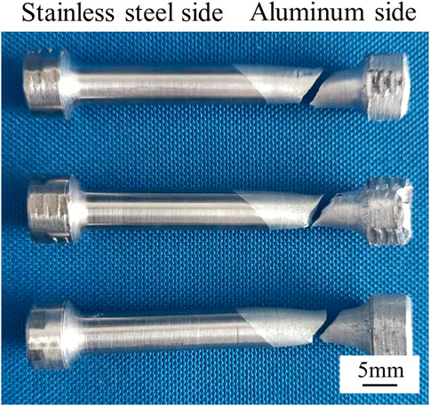
FIGURE 16. Fracture position of tensile specimens.
The characteristics of the IFW process like fast cooling rate, high-rate deformation, and difference in the thermal conductivity rate of dissimilar metal complicate the TMAZ microstructure. When the flywheel reaches the ideal rotate speed, stainless steel is moved relative to and in pressure contact with the aluminum alloy producing friction heat at the faying surfaces. The plasticity and fluidity of near-interface aluminum alloy increased, while the forging process extrudes majority of high-ductility aluminum alloy into the periphery forming a flash. A few part high-ductility aluminum alloy inside the joint generated large numbers of entanglement dislocations, and a high-value plastic strain performed by external deformation contributes to dynamic recovery/recrystallization of the matrix (Xie et al., 2021), finally forming the TMAZ region. The difference in stress state and heat dissipation condition of each part of TMAZ affects the dynamic recrystallization progress and results in differences in grain size, texture, substructure density, etc.
By comparison, because the peak temperature of the interface during rotary friction welding is in the range of 300°C–450°C lasting a very short time and the forging pressure was just set to 170 MPa which was apparently lower than the yield strength of 304 stainless steel; the stainless steel side microstructure is not obviously changed as shown by Figure 10. The steel side under finite friction heat was like a forge header to forging and extruding aluminum alloy one time.
The elemental diffusion process is critical for metallurgical bonding of dissimilar metal interfaces, and on top of that, welding heat may facilitate or retard solid diffusion. For the base metals with low solid solubility, when using pressure welding, interdiffusion of main elements will take place at the faying surface. Thick IMCs (>2 μm) reducing joint strength will not be generated until elements reached maximum solubility and were provided sufficient welding heat continuously. In this research, when the relative rotational motion of two workpieces stops, the faying surface is in close contact under the action of forging pressure, and then the main elements near the interface like Fe and Al will interdiffuse and form a diffusion layer under the influence of residual friction heat. It is notable that this solid solution layer failed to evolve into distinct IMC layer because of the fast cooling rate, but probably a kind of intermediate structure (Fukumoto et al., 2000) that efficiently reduces joint brittleness.
(1) Because of complicated thermal mechanical coupling during IFW, aluminum-side TMAZ with microstructural and microhardness heterogeneity can be divided into four different zones according to their crystallographic characteristics. Compared with the aluminum side, little microstructure change occurs on the stainless steel side.
(2) At the welding interface, the formation of IMCs was effectively controlled by fast welding cooling rate. IMCs exhibit thin and discontinuous distribution which can improve joint strength.
(3) All tensile samples fractured at the aluminum base metal side and present ductile feature. Average joint efficiency reaching 92.2% of 2219-O suggests that IFW can be successfully applied to weld dissimilar metal ring parts of aluminum and steel.
The original contributions presented in the study are included in the article/supplementary material; further inquiries can be directed to the corresponding author.
FQ: experimental design and article writing, microstructure analysis, results analysis, data processing. CZ: making of important revisions. JZ: approval of the final paper for publication. QW: carrying out of the microhardness test. YL: carrying out of the tensile test. WZ: data collection. KX: drafted revisions and conducted additional tests.
This work was supported by the “Hundred, Thousand and Ten Thousand” Major Special Science Projects of Heilongjiang Province (grant number 2020ZX03A01); and National Natural Science Foundation of China youth Science Foundation (grant number 52005139).
Authors FQ, CZ, JZ, KX, QW, YL, and WZ were employed by the company Harbin Welding Institute Limited Company.
All claims expressed in this article are solely those of the authors and do not necessarily represent those of their affiliated organizations, or those of the publisher, the editors, and the reviewers. Any product that may be evaluated in this article, or claim that may be made by its manufacturer, is not guaranteed or endorsed by the publisher.
Ashfaq, M., Sajja, N., Khalid Rafi, H., and Prasad Rao, K. (2013). Improving Strength of Stainless Steel/Aluminum Alloy Friction Welds by Modifying Faying Surface Design. J. Materi Eng. Perform. 22 (2), 376–383. doi:10.1007/s11665-012-0278-0
Dong, H., Li, Y., Li, P., Hao, X., Xia, Y., and Yang, G. (2019). Inhomogeneous Microstructure and Mechanical Properties of Rotary Friction Welded Joints between 5052 Aluminum Alloy and 304 Stainless Steel. J. Mater. Process. Tech. 272 (October), 17–27. doi:10.1016/j.jmatprotec.2019.04.039
Dong, H., Yang, J., Li, Y., Xia, Y., Hao, X., Li, P., et al. (2020). Evolution of Interface and Tensile Properties in 5052 Aluminum Alloy/304 Stainless Steel Rotary Friction Welded Joint after Post-Weld Heat Treatment. J. Manufacturing Process. 51 (March), 142–150. doi:10.1016/j.jmapro.2020.01.038
Fuji, A. (2004). Friction Welding of Al-Mg-Si alloy to Ni-Cr-Mo Low alloy Steel. Sci. Tech. Welding Joining 9 (1), 83–89. doi:10.1179/136217104225017166
Fukumoto, S., Inuki, T., Tsubakino, H., Okita, K., Aritoshi, M., and Tomita, T. (1997). Evaluation of Friction Weld Interface of Aluminium to Austenitic Stainless Steel Joint. Mater. Sci. Tech. 13 (8), 679–686. doi:10.1179/mst.1997.13.8.679
Fukumoto, S., Tsubakino, H., Okita, K., Aritoshi, M., and Tomita, T. (2000). Amorphization by Friction Welding between 5052 Aluminum Alloy and 304 Stainless Steel. Scripta Materialia 42 (8), 807–812. doi:10.1016/S1359-6462(00)00299-2
Gan, W. M., Hofmann, M., Ventzke, V., Randau, C., Huang, Y. D., Kriele, A., et al. (2016). Microstructure and Residual Stress in Rotary Friction Welded Dissimilar Metals of AA7020 Aluminium Alloy with 316L Steel. Msf 879 (November), 572–577. doi:10.4028/www.scientific.net/MSF10.4028/www.scientific.net/msf.879.572
Herbst, S., Aengeneyndt, H., Maier, H. J., and Nürnberger, F. (2017). Microstructure and Mechanical Properties of Friction Welded Steel-Aluminum Hybrid Components after T6 Heat Treatment. Mater. Sci. Eng. A 696 (June), 33–41. doi:10.1016/j.msea.2017.04.052
Huang, Y., Meng, X., Xie, Y., Wan, L., Lv, Z., Cao, J., et al. (2018). Friction Stir Welding/Processing of Polymers and Polymer Matrix Composites. Composites A: Appl. Sci. Manufacturing 105 (February), 235–257. doi:10.1016/j.compositesa.2017.12.005
Kannan, P., Balamurugan, K., and Thirunavukkarasu, K. (2015). Influence of Silver Interlayer in Dissimilar 6061-T6 Aluminum MMC and AISI 304 Stainless Steel Friction Welds. Int. J. Adv. Manuf Technol. 81 (9–12), 1743–1756. doi:10.1007/s00170-015-7288-7
Kimura, M., Ishii, H., Kusaka, M., Kaizu, K., and Fuji, A. (2009). Joining Phenomena and Joint Strength of Friction Welded Joint between Pure Aluminium and Low Carbon Steel. Sci. Tech. Welding Joining 14 (5), 388–395. doi:10.1179/136217109X425856
Kimura, M., Sakino, S., Kusaka, M., Kaizu, K., and Hayashida, K. (2020). Characteristics of Friction Welded Joint between 6063 Aluminum Alloy and AISI 304 Stainless Steel through Post-Weld Heat Treatment. J. Manufacturing Process. 58 (October), 302–310. doi:10.1016/j.jmapro.2020.08.003
Kimura, M., Suzuki, K., Kusaka, M., and Kaizu, K. (2017). Effect of Friction Welding Condition on Joining Phenomena and Mechanical Properties of Friction Welded Joint between 6063 Aluminium Alloy and AISI 304 Stainless Steel. J. Manufacturing Process. 26 (April), 178–187. doi:10.1016/j.jmapro.2017.02.008
Li, W., Vairis, A., Preuss, M., and Ma, T. (2016). Linear and Rotary Friction Welding Review. Int. Mater. Rev. 61 (2), 71–100. doi:10.1080/09506608.2015.1109214
Liu, Yong., Zhao, Haiyan., Peng, Yun., and Ma, Xiaofei. (2019a). Mechanical Properties of the Inertia Friction Welded Aluminum/Stainless Steel Joint. Weld World 11.
Liu, Y., Zhao, H., Peng, Y., and Ma, X. (2019b). Microstructure Characterization and Mechanical Properties of the Continuous-Drive Axial Friction Welded Aluminum/Stainless Steel Joint. Int. J. Adv. Manuf Technol. 104 (9–12), 4399–4408. doi:10.1007/s00170-019-04245-5
Liu, Y., Zhao, H., and Peng, Y. (2020). Metallurgical Reaction and Joining Phenomena in Friction Welded Al/Fe Joints. Int. J. Adv. Manuf Technol. 107 (3–4), 1713–1723. doi:10.1007/s00170-020-05128-w
Ma, H., Qin, G., Geng, P., Wang, S., and Zhang, D. (2021). Microstructural Characterisation and Corrosion Behaviour of Aluminium Alloy/Steel Hybrid Structure Produced by Friction Welding. J. Manufacturing Process. 61 (January), 349–356. doi:10.1016/j.jmapro.2020.11.014
Meng, X., Huang, Y., Cao, J., Shen, J., dos Santos, J. F., and dos Santos, (2021). Recent Progress on Control Strategies for Inherent Issues in Friction Stir Welding. Prog. Mater. Sci. 115 (January), 100706. doi:10.1016/j.pmatsci.2020.100706
Pinheiro, M. A., and Bracarense, A. Q. (2019). Influence of Initial Contact Geometry on Mechanical Properties in Friction Welding of Dissimilar Materials Aluminum 6351 T6 and SAE 1020 Steel. Adv. Mater. Sci. Eng. 2019 (August), 1–7. doi:10.1155/2019/1759484
Reddy, M. G., Rao, S. A., and Mohandas, T. (2008). Role of Electroplated Interlayer in Continuous Drive Friction Welding of AA6061 to AISI 304 Dissimilar Metals. Sci. Tech. Welding Joining 13 (7), 619–628. doi:10.1179/174329308X319217
Sahin, M. (2014). Characterization of Properties in Friction-Welded Austenitic-Stainless Steel and Aluminium Joints. Ind. Lubrication Tribology 66 (2), 260–271. doi:10.1108/ILT-11-2011-0100
Taban, E., Gould, J. E., and Lippold, J. C. (20101980-2015). Dissimilar Friction Welding of 6061-T6 Aluminum and AISI 1018 Steel: Properties and Microstructural Characterization. Mater. Des. (1980-2015) 31 (5), 2305–2311. doi:10.1016/j.matdes.2009.12.010
Wan, L., and Huang, Y. (2018). Friction Welding of AA6061 to AISI 316L Steel: Characteristic Analysis and Novel Design Equipment. Int. J. Adv. Manuf Technol. 95 (9–12), 4117–4128. doi:10.1007/s00170-017-1505-5
Wang, H., Qin, G., Geng, P., and Ma, X. (2020). Interfacial Microstructures and Mechanical Properties of Friction Welded Al/Steel Dissimilar Joints. J. Manufacturing Process. 49 (January), 18–25. doi:10.1016/j.jmapro.2019.11.009
Xie, Y., Meng, X., Li, Y., Mao, D., Wan, L., and Huang, Y. (2021). Insight into Ultra-refined Grains of Aluminum Matrix Composites via Deformation-Driven Metallurgy. Composites Commun. 26 (August), 100776. doi:10.1016/j.coco.2021.100776
Keywords: dissimilar metal welding, inertial friction welding, aerospace, EBSD, microstructure
Citation: Qin F, Zhang C, Zhou J, Xu K, Wang Q, Li Y and Zhang W (2022) Microstructure and Mechanical Properties of Aluminum Alloy/Stainless Steel Dissimilar Ring Joint Welded by Inertia Friction Welding. Front. Mater. 8:813118. doi: 10.3389/fmats.2021.813118
Received: 11 November 2021; Accepted: 26 November 2021;
Published: 05 January 2022.
Edited by:
Xiangchen Meng, Harbin Institute of Technology, ChinaReviewed by:
Yunqiang Zhao, Guangdong Academy of Science (CAS), ChinaCopyright © 2022 Qin, Zhang, Zhou, Xu, Wang, Li and Zhang. This is an open-access article distributed under the terms of the Creative Commons Attribution License (CC BY). The use, distribution or reproduction in other forums is permitted, provided the original author(s) and the copyright owner(s) are credited and that the original publication in this journal is cited, in accordance with accepted academic practice. No use, distribution or reproduction is permitted which does not comply with these terms.
*Correspondence: Jun Zhou, bWNoX3pob3VqdW5AMTI2LmNvbQ==
Disclaimer: All claims expressed in this article are solely those of the authors and do not necessarily represent those of their affiliated organizations, or those of the publisher, the editors and the reviewers. Any product that may be evaluated in this article or claim that may be made by its manufacturer is not guaranteed or endorsed by the publisher.
Research integrity at Frontiers
Learn more about the work of our research integrity team to safeguard the quality of each article we publish.