 Aniruddh Das
 Eberhard Altstadt
 Cornelia Kaden1
 Garima Kapoor
 Frank Bergner
- 1Helmholtz-Zentrum Dresden-Rossendorf, Dresden, Germany
- 2Chair of Radiochemistry/Radioecology, Technische Universität Dresden, Dresden, Germany
Nanoindentation of ion-irradiated nuclear structural materials and model alloys has received considerable interest in the published literature. In the reported studies, the materials were typically exposed to irradiations using a single ion energy varying from study to study from below 1 MeV to above 10 MeV. However, systematic investigations into the effect of self-ion energy are still insufficient, meaning that the possibilities to gain insight from systematic energy variations are not yet exhausted. We have exposed pure Fe, ferritic Fe-9Cr, martensitic Fe-9Cr and the ferritic-martensitic reduced-activation steel Eurofer 97 to ion irradiations at 300°C using 1, 2 and 5 MeV Fe2+ ions as well as 8 MeV Fe3+ ions and applied nanoindentation, using a Berkovich diamond indenter, to characterize as-irradiated samples and unirradiated references. The effect of the ion energy on the measured nanoindentation response is discussed for each material. Two versions of a primary-damage-informed model are applied to fit the measured irradiation-induced hardening. The models are critically compared with the experimental results also taking into account reported microstructural evidence. Related ion-neutron transferability issues are addressed.
1 Introduction
Ion irradiation of nuclear structural materials and model alloys offers an alternative to neutron irradiation resulting in similar material damage at faster rates, lower costs, with better control of the irradiation conditions, and without activation. To date depth-sensing nanoindentation (NI) of ion-irradiated materials has received much interest in the published literature; see for example (Zinkle and Oliver, 1986; Rice and Stoller, 1997; Robertson et al., 1998; Yutani et al., 2007; Halliday et al., 2009; Heintze et al., 2009; Hosemann et al., 2009). A recent review was worked out by Xiao and Yu (2020).
In the reported studies, the materials were typically exposed to self-ion irradiations using a single ion energy varying from study to study from below 1 MeV (Clozel et al., 2020) to above 10 MeV (Song et al., 2020). As reported by Ruiz-Moreno et al. (2020) in conclusion for a Round Robin test, simple comparison of NI results from different laboratories is, however, still problematic. Saleh et al. (2016) studied the effect of energy variations of He ions (including ion energies of 1, 2 and 3 MeV) on the NI response of an austenitic stainless steel. These authors provided a rationalization of the peak position in hardening versus indentation depth curves. A standard comparison between different studies is difficult since one or more of the following parameters are varied: ion energy, ion specie, irradiation dose, irradiation temperature, single or multi-beam irradiation and target material. The present study covers a systematic variation of the Fe-ion energy (including energies of 1, 2, 5 and 8 MeV keeping all other irradiation parameters controlled) applied to a set of four materials, namely pure Fe, ferritic Fe-9Cr, martensitic Fe-9Cr and the reduced-activation ferritic/martensitic steel Eurofer 97.
Eurofer 97 is a primary candidate for application in nuclear fusion devices. The other three selected materials are model alloys aimed at achieving a better understanding of the effect of material variables. Pure Fe was chosen as a reference material. Ferritic Fe-9Cr allows the Cr effect to be extracted. Martensitic Fe-9Cr, as compared to ferritic Fe-9Cr, provides access to the effect of the microstructure. Eurofer 97 also exhibits a martensitic microstructure but differs from the former with respect to the presence of carbides and precipitates.
The first objective is to demonstrate the effect of the ion energy on the NI response in terms of irradiation-induced hardness increase as a function of the indentation contact depth. Similarities and differences of the observations for the four materials will be discussed. It is important to note that a minimum ion energy in the range from 5 to 10 MeV was recommended by Zinkle and Snead (2018) and Doyle et al. (2018) in order for the ion-irradiated microstructure to be representative of neutron-irradiated microstructures at least in a certain depth range. The presence of such a range was recently confirmed by cross-sectional STEM for a ferritic Fe-9Cr alloy irradiated using 5 MeV Fe ions, while 1 MeV was insufficient for a neutron-representative microstructure to be formed (Vogel et al., 2021). In essence, the present study covers ion energies below and within the desired range of ion energies.
In order to further rationalize the observations of the present study, two versions of a primary-damage-informed model of irradiation hardening are applied. The first version, introduced before by Kareer et al. (2018), assumes linear superposition of the indentation size effect (ISE) according to Nix and Gao (1998) and the irradiation effect. The second version, introduced before by Röder et al. (2018), also assumes linear superposition of the irradiation effect, but within the H0 term of the Nix-Gao formulation (H0 is the bulk-equivalent hardness). Previous efforts to apply primary-damage-informed models were limited to the consideration of displacement damage as a primary damage parameter, whereas direct effects of the injected ions were ignored. In the present study, the depth-dependent concentration of injected interstitials, as revealed by the binary collision code SRIM, is taken into account. It is also important to point out that a comparison of linear and square superposition of the ISE and the irradiation effect was reported by Xiao and Yu (2018). These authors found out that the ratio of irradiated and unirradiated hardness exhibits a peak and that the peak range is equally well described by linear and square superposition, while the larger-depth tail is better described by square superposition. The present study is, however, restricted to linear superposition, because we are most interested in the peak range and wish to be consistent with the studies by Kareer et al. (2018) and Röder et al. (2018).
2 Experiments
2.1 Materials and Irradiations
The set of materials selected for the present study covers pure Fe, a ferritic Fe-9Cr alloy, a martensitic Fe-9Cr alloy and the reduced-activation ferritic/martensitic steel Eurofer 97. For fabrication details and analyses see (Matijasevic and Almazouzi, 2008; Matijasevic et al., 2008; Konstantinović and Malerba, 2020). Cr content, type of microstructure, mean grain size, Vickers hardness (HV10 - load 98.1 N), and yield stress are summarized in Table 1.
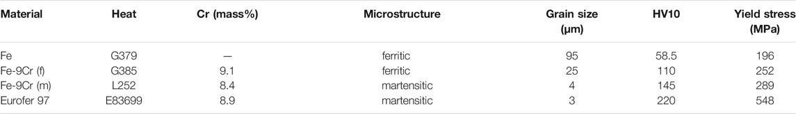
TABLE 1. Microstructural details and mechanical properties of the as-received materials.
Samples of size 10 × 10 × 1 mm3 were cut from the as-received pieces of material followed by a one-sided preparation consisting of grinding at stepwise decreasing grain size up to P4000, polishing using polishing clothes MD-Dac, MD-Nap and MD-Chem (Struers), and electrolytic polishing (2% perchloric acid, 3 min, 6°C, 40 V, stirring). Plasma cleaning was applied to the samples immediately before mounting them on the irradiation sample holder and into the vacuum chamber of the ion-irradiation beamline.
Ion irradiation was performed at the 3 MV tandetron accelerator of the Ion Beam Center located at HZDR Dresden, Germany. Samples of each material were exposed to Fe2+ ions of 1, 2 and 5 MeV and Fe3+ ions of 8 MeV energy by uniformly scanning the ion beam across the sample surface. The irradiation temperature measured at the back side of the samples was 300°C. A vacuum of typically 2·10–5 Pa was maintained in the irradiation chamber. The displacement damage and concentration of injected Fe interstitials calculated using the binary collision code SRIM (Ziegler et al., 2010) [quick calculation mode, lattice binding energy and surface binding energy set to zero, displacement energy 40 eV (Stoller et al., 2013)] are plotted in Figure 1. The irradiation time was adjusted such that the accumulated displacement damage averaged over the depth range from 0 to 1 µm is 1 displacement per atom (dpa) for each ion energy as indicated by the dashed line.

FIGURE 1. Depth profiles of (A) displacement damage and (B) concentration of injected interstitials. The dashed line indicates 1 dpa i.e., the accumulated displacement damage over the depth range from 0 to 1 µm.
2.2 Nanoindentation Testing
A UNAT-type of device (ASMEC GmbH) equipped with a Berkovich diamond indenter was utilized for nanoindentation testing. A number of 40 indentations with 40 µm spacing between adjacent indents were set for each sample in load control with maximum loads of 50 mN. The loading cycle consisted of an approach segment aimed at finding the surface, a load increase segment comprising quasi-continuous stiffness measurements (Röder et al., 2018) automatically conducted at 75 equidistant loads, a creep segment of 20 s duration at maximum load, an unloading segment to 5 mN in 8 s, and a thermal drift segment of 60 s at 5 mN. The method suggested by Oliver and Pharr (1992) was applied to obtain average curves of indentation hardness as a function of contact depth. The experimental errors of indentation hardness reported in this study are standard deviations. The same indenter with the same area function derived beforehand according to standard DIN EN ISO 14577-1:2015-11 (2015) was used for the whole set of samples for the sake of consistency.
3 Modeling
From the point of view of a black box approach, we consider the z-dependent damage (z = distance from the irradiated surface) caused by ion irradiations as a stimulus (or input) and the resulting hardness increase as function of contact depth as the response (or output). The input is given in Figure 1 in terms of displacement damage D and concentration of injected ions I, both as functions of z and the ion energy E. The output is the hardness increase ΔHIT as a function of the contact depth hc. At difference from a typical black box, models are available in the present case. We express the local hardness increase due to irradiation-induced obstacles developed at a depth z according to
α, β and p are fit parameters that formally describe the material’s sensitivity to displacement damage and injected ions. It is immediately clear that, by setting β to zero, the local hardening is a power-law function of the displacement damage (or fluence) alone as frequently reported or assumed in the literature, e.g., (Byun and Farrell, 2004), and as applied before for the purpose of modeling of nanoindentation (Kareer et al., 2018; Röder et al., 2018). In contrast, a possible additional hardening effect of the injected ions has rarely been considered.
The hardness of an unirradiated material can be represented according to Eq. 2 (Nix and Gao, 1998):
We will call this model 1. The subscript i refers to the ion-irradiated material. Consistent with (Kareer et al., 2018), the major irradiation effect within model 1 comes directly from the irradiation-induced obstacles included in the second term of Eq. 3,
The second approach, suggested by (Röder et al., 2018), assumes that the irradiation effect is also superimposed linearly, but solely inside the
We will call this model 2. In contrast with model 1,
In this study, we are going to apply models 1 and 2 in order to fit the measured irradiation-induced hardness increase as function of contact depth. If we write down the difference
R = chc is the radius of the plastic zone assumed to be a half-sphere and c is a constant, the so called plastic zone extension factor. If
It is important to point out that Xiao and Yu (2018) compared linear superposition of the ISE and the irradiation effect with square superposition. The linear superposition in their study resembles the Kareer approach with respect to how the irradiation effect is superimposed with the ISE. Xiao and Yu came to the conclusion that the experimental data are fitted equally well for both types of superposition (linear and square) in the depth range of maximum irradiation hardening. As this is the range of interest in the present study, we restrict ourselves to linear superposition for the purpose of comparing the applicability of models 1 and 2 introduced above.
Values of the four (α, p, β, and c according to model 1) or five (α, p, β, c and
Our approach is based on a number of assumptions. To repeat, these include the approximate applicability of linear superposition of the hardness of the pristine material and the irradiation-induced hardness increase. The size and the half-sphere shape of the indentation plastic zone are assumed to be effectively equal for the pristine and irradiated material, but may vary from material to material. We also neglect possible interaction between injected ions, which mainly become self-interstital atoms, and loops formed due to displacement damage. The observation (to be made below) that major features of the measured hardening are well reproduced by the predictions will justify the choice of assumptions in retrospect.
4 Results
4.1 Experimental Results
The results of the nanoindentation tests for the unirradiated and all ion-irradiated conditions of the four materials are plotted in Figure 2 in terms of indentation hardness HIT as a function of contact depth hc. The axes of the plots are scaled consistently to facilitate comparison among different materials. The tests also revealed the indentation modulus (not shown). As a general trend, the indentation modulus forms a narrow band for all materials and irradiation conditions reaching approximately the modulus of elasticity for larger contact depth and increasing at decreasing contact depth by about 50%. No modulus correction was applied throughout the present study.
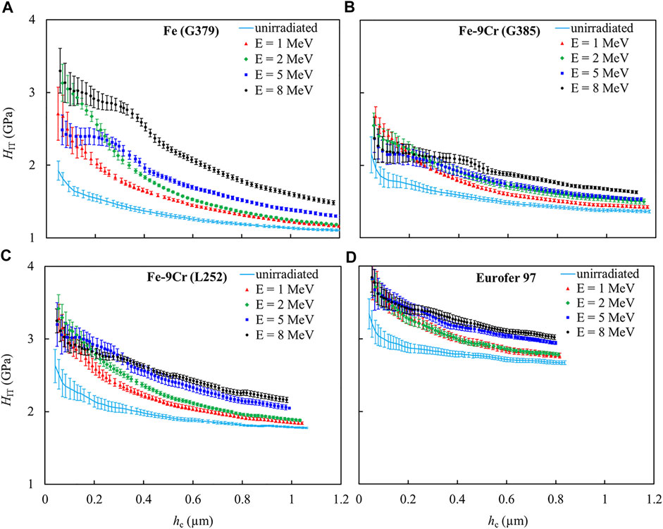
FIGURE 2. Measured indentation hardness as a function of contact depth for the unirradiated and ion-irradiated conditions of (A) Pure Fe (G379), (B) ferritic Fe-9Cr (G385), (C) martensitic Fe-9Cr (L252) and (D) Eurofer 97.
The nanohardness curves of the unirradiated samples of each material exhibit an ISE. The square of indentation hardness (HIT2) was plotted against the reciprocal of the contact depth (1/hc) according to Nix and Gao (1998) and fitted by straight lines excluding the range of smallest contact depth (hc less than approximately 0.3 µm), where the Nix-Gao model is violated (Huang et al., 2006). The resulting plots are presented in Figure 3. The derived values of H0 and
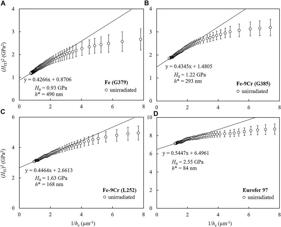
FIGURE 3. Nix-Gao plots for the unirradiated conditions of (A) Pure Fe (G379), (B) ferritic Fe-9Cr (G385), (C) martensitic Fe-9Cr (L252) and (D) Eurofer 97, regression lines excluding the range of smallest hc values, and derived Nix-Gao parameters.
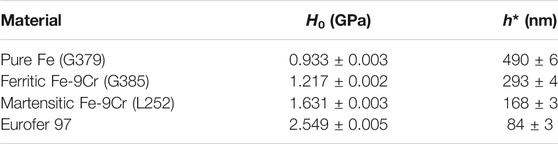
TABLE 2. Summary of Nix-Gao parameters for the unirradiated reference samples. Errors were derived from the statistical errors of the slope and intercept of the regression lines.
The indentation hardness of all irradiation conditions increases as compared to the unirradiated references (Figure 2). This increase is highest for pure Fe. With the possible exception of pure Fe, the indentation hardness curves of the irradiated conditions tend to come close to each other at certain contact depths in the range around 0.2 µm irrespective of the ion energy. For the smallest contact depths, below 0.1 µm, the experimental errors obscure a clear ranking with respect to the ion energy. For the largest contact depths, an increase of the indentation hardness at increasing ion energy is observed. The variation of the maximum contact depth reached for each material is a consequence of the maximum load of 50 mN in the indentation experiments maintained throughout this study.
In order to get a clearer view on the irradiation effect, the indentation hardness of the respective unirradiated reference conditions was subtracted from the indentation hardness of the irradiated conditions. The results along with the experimental errors are plotted in Figure 4. The experimental hardening curves also appear as a reference to the model curves in the next section.
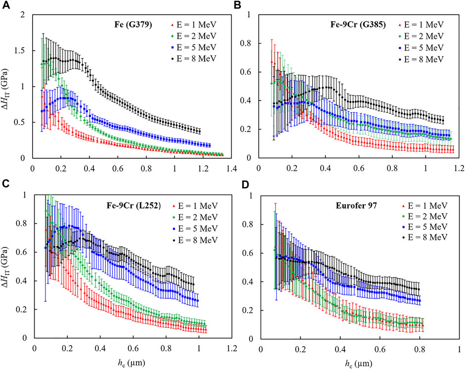
FIGURE 4. Irradiation-induced indentation hardness change as function of contact depth for the ion-irradiated conditions of (A) Pure Fe (G379), (B) ferritic Fe-9Cr (G385), (C) martensitic Fe-9Cr (L252) and (D) Eurofer 97.
The most prominent observation is that the hardness differences ΔHIT as function of hc exhibit peaks except for both Eurofer 97 and the 1 MeV irradiations of all materials. Moreover, the peak positions tend to be shifted towards smaller contact depths at decreasing ion energy. For the 1 MeV irradiations, possible peaks might be located at depths below the range of measurement. For Eurofer 97, there are shoulders instead of peaks. The experimentally obtained hardness differences will be used in the next section for curve fitting.
4.2 Results of Modeling
We first applied model 1. As explained in Section 3, this was realized using four parameters (c, α, β and p) to fit Eqs 1, 5 to the experimental data keeping
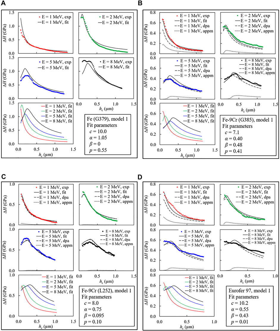
FIGURE 5. | Indentation hardness increase vs contact depth plots showing experimental curves (symbols), model 1 fitted curves (solid lines) along with the individual contribution curves from displacement damage (dashed lines) and injected ions (dotted lines) for all the materials at all ion energies. A comparison plot for all fitted curves of different ion energies is additionally shown along with the best-fit parameters (A) Pure Fe (G379), (B) ferritic Fe-9Cr (G385), (C) martensitic Fe-9Cr (L252), (D) Eurofer 97.
We found that the fitted curves generally well represent the main features (peaks and tails) of the experimental curves as well as the effect of the change in ion energy. Most importantly, the existence and positions of the peaks of the fitted curves for all materials except for Eurofer 97 are in line with the experimental results. In agreement with the experimental curves, the peak positions are shifted to higher contact depths at increasing ion energy. For Eurofer 97, there are peaks in the fitted curves instead of shoulders in the experimental curves (Figure 5D). We shall see later that model 2, using the five-parameter fit, will also give rise to shoulders in the fitted curves. Along with the root mean square (RMS) deviation between prediction and measurement, the best-fit parameters are listed in Table 3, they will be discussed later. The values of the plastic zone extension factor c estimated from the yield stresses (Table 1) using the expanding cavity model (Johnson, 1970) are also included in Table 3.
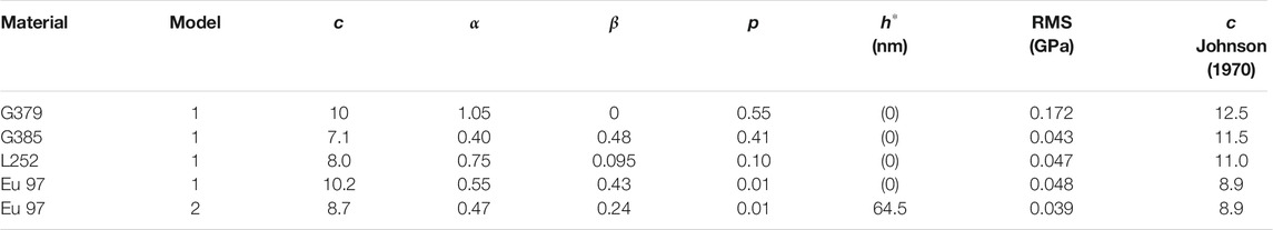
TABLE 3. Summary of fit parameters, resulting root mean square (RMS) deviation, and c values predicted from the expanding cavity model (Johnson, 1970) (see discussion).
The values of α and β cannot be compared directly because of the different units used for displacement damage and injected ions. Instead, the individual hardening contributions arising from either displacement damage or injected interstitials alone have to be compared. This is achieved by setting one of the contributions to zero in Eqs 1, 5 and keeping the other parameters fixed. We have found that the contribution from injected ions (dotted lines in Figure 5) is significantly smaller as compared to the contribution from displacement damage (dashed lines in Figure 5) for all the materials and energies.
The results of the five-parameter fits of model 2 for Eurofer 97 are shown in Figure 6 in comparison with the corresponding four-parameter fits of model 1. The best-fit parameters obtained for model 2 applied to Eurofer 97 is also included in Table 3. Model 2 shows a better fit with the experimental curves as compared to model 1. Most prominently, the peaks obtained for model 1 are replaced by shoulders for model 2, while the position of the beginning of the shoulders remains approximately the same as the position of the peaks. This is a consequence of the variation of

FIGURE 6. Comparison of the model 1 fit (A) with the model 2 fit (B) for Eurofer 97.
5 Discussion
5.1 Role of the Initial Microstructure
The indentation size effect, marked by higher hardness values for smaller contact depths, is observed for all materials (Figure 2). This effect was described by Nix and Gao and was attributed to the balance of statistically stored and geometrically necessary dislocations (Nix and Gao, 1998). The bulk-equivalent hardness H0 of the unirradiated materials (Figure 3 and Table 2) follows the order: pure Fe → ferritic Fe-9Cr → martensitic Fe-9Cr → Eurofer 97, from lowest to highest hardness. This order is qualitatively consistent with the ranking of the materials in terms of solution hardening (composition), Hall-Petch hardening (grain size), forest hardening (dislocation density) and precipitation hardening. Indeed, the alloying and impurity levels, inverse grain sizes (Table 1), dislocation densities (ferritic versus martensitic microstructures) and volume fractions of precipitates (model alloys versus steel) follow the same trend. The characteristic length of the unirradiated materials follows the opposite order, that means
The indentation hardness of the irradiated materials is higher as compared to their unirradiated counterparts for each material and each ion energy (Figure 2). The reason why pure Fe exhibits the highest hardness increase (for all ion energies) amongst the present set of materials is the lower density of available point-defect sinks present in the microstructure (Was, 2007; Duan et al., 2017). Eurofer 97, which is expected to exhibit the highest sink strength, shows smaller irradiation hardening as compared with pure Fe, which is reasonable. Martensitic Fe-9Cr is in between with respect to both sink strength and irradiation hardening. Ferritic Fe-9Cr does not follow the expected trend. This might be related to the band-like irradiation-induced microstructure reported in (Vogel et al., 2021).
5.2 Effect of the Ion Energy
The present study is focussed on the irradiation effect, in particular the effect of ion energy. The understanding of the irradiation effect in terms of a softer substrate effect introduced by Kasada et al. (2011) is partly insufficient here. Indeed, the damage profiles shown in Figure 1 cannot be approximated as a homogeneous layer. It is necessary to take the profiles of displacement damage and injected ions explicitly into consideration, see Eq. 1. This was done before by several authors including (Kareer et al., 2018; Röder et al., 2018) for the displacement damage, but not for the injected ions. The models used in this study take into account both of them. In addition to the empirical interpretation of the as-measured irradiation hardening, these models provide insight on the way how certain model details (or parameters) influence the shape of the ΔHIT-hc curves.
We have found that the fits of the irradiation-induced change of hardness using model 1 reproduce the positions of the as-measured hardening peaks as function of the ion energy for pure Fe and the Fe-9Cr alloys reasonably well (Figure 5). Indeed, the positions of the peaks of irradiation hardening derived from model 1 are shifted towards larger depths for increasing ion energy, as experimentally observed. It can be concluded that the dominant factor governing the peak positions are the damage profiles of Eq. 1 (see Figure 1), from which the peaks propagate via Eq. 5 to the fitted curves. The suitability of the four-parameter model 1 (i.e. Kareer approach) also indicates that the type of superposition between ISE and irradiation effect expressed in Eq. 3 is sufficient, meaning that the ISE cancels out in the irradiation-induced hardness increase.
For Eurofer 97, similar conclusions can be drawn from the application of model 1 with the exception that model 1 necessarily predicts peaks of the ΔHIT-hc curves, while shoulders are observed experimentally (Figure 5D). We have found that the shoulders are correctly described using model 2 (Figure 6B). This is the consequence of the additional parameter
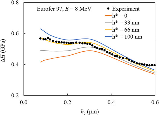
FIGURE 7. Application of model 2 with the indicated variations of the parameter
It can be summarized that model 1 (Kareer approach) describes the peaks for pure Fe and the Fe-9Cr model alloys well, while application of model 2 (Röder approach) becomes necessary to reproduce the shoulders for Eurofer 97. The question is then, what is special about Eurofer 97 in this respect. We assume that the difference is due to Eurofer 97 exhibiting the highest unirradiated hardness (Figure 2D) in combination with the lowest relative irradiation-induced hardness increase (Figure 4D). Both aspects are linked to the microstructure, the former in terms of hardening mechanisms and the second in terms of sink strength. It is important to note that application of model 2 to pure Fe and the Fe-9Cr alloys would not be particularly meaningful. This is because the four-parameter fit already reproduces the major features for these materials. While introducing an additional parameter (namely
Another observation is the tendency of the ΔHIT-hc curves corresponding to the different ion energies to come close to each other at lower contact depths (Figure 4). Both models reproduce this tendency. We remind that the average displacement damage in the z-range from 0 to 1 µm was intentionally chosen to be 1 dpa for each ion energy. Hence, the coming together of the ΔHIT-hc curves at contact depths between 0.1 and 0.2 µm (Figures 4–6), for which the extension of the plastic zone is around 1 μm, can only be explained if the contribution to the irradiation hardening arising from the displacement damage prevails over the contribution of the injected ions. This implication is strengthened by the application of the models (dashed lines versus dotted lines in Figures 5, 6). It should however, be pointed out that the calculated contribution of injected ions is not negligible at least for some of the materials, most prominently for ferritic Fe-9Cr. This means that the non-consideration of the effect of the injected ions by most authors (Kasada et al., 2011; Xiao et al., 2017; Kareer et al., 2018; Röder et al., 2018) is not always justified. A possible reason is the presence of a pronounced band-like irradiation-induced microstructure in ferritic Fe-9Cr (Vogel et al., 2021), for which the injected interstitials seem to play a decisive role.
The third noticeable observation is the ranking as function of the ion energy of the indentation hardness at higher values of the contact depth; say 0.8 µm (Figure 2). Indeed, the higher the ion energy, the larger the irradiation-induced hardness increase at 0.8 µm for each material. Both models reproduce this behavior equally well (Figures 5, 6). The reason of this ranking is related to the damage profiles plotted in Figure 1. A contact depth of 0.8 µm corresponds to a radius of the plastic zone around 7 µm. A higher ion energy then gives rise to a larger fraction of the irradiated layer (or smaller fraction of the unaffected substrate) in the volume of the plastic zone resulting in a higher indentation hardness.
The same reasoning from another point of view is also important at small contact depths. The higher the ion energy, the wider is the range of negligible concentration of injected ions, see Figure 1B. Such a range is extremely shallow for 1 MeV, while it reaches from the sample surface up to a depth of approximately 1 µm for 8 MeV. As the injected ions represent a transferability issue between ion irradiation of a material and neutron irradiation, a wide range of negligible concentration of injected ions was reported to be vital for the application of ion irradiations to emulate neutron irradiation effects (Zinkle and Snead, 2018; Vogel et al., 2021). This insight is independent of the applied characterization method. For nanoindentation, however, it is important to take into account that the indentation plastic zone needs to be fully enclosed in the depth range of negligible concentration of injected ions. It follows that the maximum contact depth, which is smaller than the plastic zone radius by a factor of c (7 ≤ c ≤ 10 according to Table 3), should be of the order of 0.1 µm or smaller for 8 MeV. This corresponds to the smallest contact depths recorded in this study. Explicit comparisons of the nanoindentation results reported here for ion-irradiated samples with mechanical property changes of neutron-irradiated samples of the same alloys will be addressed in a future study.
It is important to point out that our modeling approach offers another possibility to cope with the ions – neutrons transferability issue. Indeed, Eq. 1 can be used to separate the hardening contributions arising from displacement damage and injected ions. The displacement damage contribution takes the form
5.3 Best-Fit Values of the Model Parameters
The best-fit values of the extension factor of the indentation plastic zone c (= R/hc) are between 7.1 and 10 for the materials of this study (Table 3). This is consistent with the range from 5 to 10 reported in the literature (Kramer et al., 1998; Hosemann et al., 2012; Dolph et al., 2016; Saleh et al., 2016; Xiao et al., 2017; Kareer et al., 2018; Röder et al., 2018; Vogel et al., 2020). The value of c can be predicted in the framework of the expanding cavity model (Johnson, 1970) assuming an elastic – ideally plastic material. Based on the yield stresses listed in Table 1, predicted c values are given in Table 3. These predictions tend to overestimate the fit values (by up to 60%). They also tend to be higher as compared to the range reported in the literature. The plastic zone is predicted to be larger for a softer material like pure Fe (G379); hence, a high c value of 10 seems reasonable, while the harder materials exhibit lower c values. For the hardest material Eurofer 97, the prediction suggests model 2 to be more reasonable than model 1.
The values of α and β cannot be interpreted directly. Instead, the resulting hardening contributions have to be compared. We have found that the contribution of injected ions (β term) is negligible for pure Fe and martensitic Fe-9Cr, while a significant contribution, although smaller than the contribution from displacement damage, is indicated for ferritic Fe-9Cr and Eurofer 97. For ferritic Fe-9Cr the role of the injected ions may be related to the pronounced band-like irradiation-induced microstructure (Vogel et al., 2021). For the other materials, more microstructural evidence is needed. The displacement damage exponent p ranges from 0.01 for Eurofer 97 to 0.55 for G379, i.e. it monotonically increases at decreasing initial hardness (Table 3). The displacement damage exponent was reported earlier to be close to 0.55 and 0.12 (average values for bcc alloys) for low and high doses, respectively (Byun and Farrell, 2004). In the range of displacement damage (dose) around 1 dpa (Figure 1A) applied in our study, the dose dependence of hardening for pure Fe (p = 0.55) and ferritic Fe-9Cr (p = 0.41) can be approximated as a square-root dependence as often suggested in the literature (Byun and Farrell, 2004; Saleh et al., 2016). In contrast, martensitic Fe-9Cr and Eurofer 97 exhibit a saturation like behavior. This is in agreement with the weak dose dependence (or intermediate saturation) in the range from below 1 dpa up to 10 dpa observed for Fe-Cr alloys including the present heat L252 of the martensitic Fe-9Cr alloy (Heintze et al., 2011).
The best-fit value of
6 Conclusion
In this work, depth sensing nanoindentation using a Berkovich indenter was used to study the effect of the ion energy on the irradiation-induced hardness increase of Fe, ferritic Fe-9Cr, martensitic Fe-9Cr and the 9Cr ferritic/martensitic steel Eurofer 97. Two versions of a primary-damage-informed model were considered. Model 1 is based on linear superposition of irradiation hardening with the unirradiated hardness exhibiting the ISE [Kareer approach, Kareer et al. (2018)]. Model 2 adds irradiation hardening inside the H0 term of the ISE of the unirradiated material [Röder approach, (Röder et al., 2018)]. It was demonstrated that model 1 can be formally derived from model 2 by setting the characteristic length
• The peaks in the ΔHIT-hc curves observed for Fe and the Fe-9Cr alloys tend to move towards higher contact depths with increasing ion energy. This is because the profiles of both displacement damage and injected ions also reach deeper into the material. The peaks are reproduced by model 1.
• For Eurofer 97, shoulders were observed instead of peaks. Model 2 describes how the peaks transform into shoulders by raising the value of the characteristic length parameter
• For larger contact depths, an increase of the indentation hardness with increasing ion energy is observed in accordance with both models. This is because the fraction of unirradiated substrate within the half-sphere plastic zone of given radius decreases at higher ion energies.
• Application of the models reveals that the contribution from injected ions is in general smaller as compared to the contribution from displacement damage or even vanishes.
• For an ion energy of 8 MeV, the concentration of injected interstitials is negligible throughout the indentation plastic zone for contact depths of 0.12 µm or smaller. This indicates an approach to exclude the injected ions effect as an ions – neutrons transferability issue. Moreover, our approach offers a possibility to isolate the contribution from displacement damage, which can be directly compared to the case of neutron irradiation.
It is important to remind that, as an approximation, the half-sphere plastic zone extension factor c (both models) and the characteristic length
Data Availability Statement
The datasets presented in this study can be found in online repositories. The names of the repository/repositories and accession number(s) can be found below: https://dx.doi.org/10.14278/rodare.1250.
Author Contributions
FB and AD contributed to the conception and design of the study. FB and CK were in charge of the experiments. SA facilitated the ion irradiation experiments. FB and AD performed the analysis and developed models. EA developed the code. FB and AD wrote the first draft of the manuscript. FB, AD, EA and GK contributed to the manuscript revision and proofreading.
Funding
Funding for the open access publication is received from the library of Helmholtz-Zentrum Dresden-Rossendorf, Dresden, Germany.
Conflict of Interest
The authors declare that the research was conducted in the absence of any commercial or financial relationships that could be construed as a potential conflict of interest.
Publisher’s Note
All claims expressed in this article are solely those of the authors and do not necessarily represent those of their affiliated organizations, or those of the publisher, the editors, and the reviewers. Any product that may be evaluated in this article, or claim that may be made by its manufacturer, is not guaranteed or endorsed by the publisher.
Acknowledgments
This work contributes to the Joint Programme on Nuclear Materials (JPNM) within the European Energy Research Alliance (EERA). The ion irradiations were performed at the Ion Beam Center at Helmholtz-Zentrum Dresden-Rossendorf (HZDR). The authors gratefully acknowledge the support from the HZDR Ion Beam Center. The authors wish to express their gratitude to W. Webersinke and M. Roßner for their valuable assistance.
References
Byun, T. S., and Farrell, K. (2004). Irradiation Hardening Behavior of Polycrystalline Metals after Low Temperature Irradiation. J. Nucl. Mater. 326, 86–96. doi:10.1016/j.jnucmat.2003.12.012
Clozel, M., Kurpaska, L., Jóźwik, I., Jagielski, J., Turek, M., Diduszko, R., et al. (2020). Nanomechanical Properties of Low-Energy Fe-Ion Implanted Eurofer97 and Pure Fe. Surf. Coat. Tech. 393, 125833. doi:10.1016/j.surfcoat.2020.125833
DIN EN ISO 14577-1:2015-11 (2015). Metallic Materials - Instrumented Indentation Test for Hardness and Materials Parameters - Part 1: Test Method (ISO 14577-1:2015); German Version EN ISO 14577-1:2015. Berlin: Beuth Verlag GmbH. doi:10.31030/2055269
Dolph, C. K., da Silva, D. J., Swenson, M. J., and Wharry, J. P. (2016). Plastic Zone Size for Nanoindentation of Irradiated Fe–9%Cr ODS. J. Nucl. Mater. 481, 33–45. doi:10.1016/j.jnucmat.2016.08.033
Doyle, P. J., Benensky, K. M., and Zinkle, S. J. (2018). Modeling the Impact of Radiation-Enhanced Diffusion on Implanted Ion Profiles. J. Nucl. Mater. 509, 168–180. doi:10.1016/j.jnucmat.2018.06.042
Duan, B., Heintze, C., Bergner, F., Ulbricht, A., Akhmadaliev, S., Oñorbe, E., et al. (2017). The Effect of the Initial Microstructure in Terms of Sink Strength on the Ion-Irradiation-Induced Hardening of ODS Alloys Studied by Nanoindentation. J. Nucl. Mater. 495, 118–127. doi:10.1016/j.jnucmat.2017.08.014
Halliday, F. M., Armstrong, D. E. J., Murphy, J. D., and Roberts, S. G. (2009). Nanoindentation and Micromechanical Testing of Iron-Chromium Alloys Implanted with Iron Ions. Adv. Mater. Res. 59, 304–307. doi:10.4028/www.scientific.net/AMR.59.304
Heintze, C., Bergner, F., and Hernández-Mayoral, M. (2011). Ion-irradiation-induced Damage in Fe-Cr Alloys Characterized by Nanoindentation. J. Nucl. Mater. 417, 980–983. doi:10.1016/j.jnucmat.2010.12.196
Heintze, C., Recknagel, C., Bergner, F., Hernández-Mayoral, M., and Kolitsch, A. (2009). Ion-irradiation-induced Damage of Steels Characterized by Means of Nanoindentation. Nucl. Instr. Methods Phys. Res. Section B: Beam Interactions Mater. Atoms 267, 1505–1508. doi:10.1016/j.nimb.2009.01.122
Hosemann, P., Kiener, D., Wang, Y., and Maloy, S. A. (2012). Issues to Consider Using Nano Indentation on Shallow Ion Beam Irradiated Materials. J. Nucl. Mater. 425, 136–139. doi:10.1016/j.jnucmat.2011.11.070
Hosemann, P., Vieh, C., Greco, R. R., Kabra, S., Valdez, J. A., Cappiello, M. J., et al. (2009). Nanoindentation on Ion Irradiated Steels. J. Nucl. Mater. 389, 239–247. doi:10.1016/j.jnucmat.2009.02.026
Huang, Y., Zhang, F., Hwang, K., Nix, W., Pharr, G., and Feng, G. (2006). A Model of Size Effects in Nano-Indentation. J. Mech. Phys. Sol. 54, 1668–1686. doi:10.1016/j.jmps.2006.02.002
Johnson, K. L. (1970). The Correlation of Indentation Experiments. J. Mech. Phys. Sol. 18, 115–126. doi:10.1016/0022-5096(70)90029-3
Kareer, A., Prasitthipayong, A., Krumwiede, D., Collins, D. M., Hosemann, P., and Roberts, S. G. (2018). An Analytical Method to Extract Irradiation Hardening from Nanoindentation Hardness-Depth Curves. J. Nucl. Mater. 498, 274–281. doi:10.1016/j.jnucmat.2017.10.049
Kasada, R., Takayama, Y., Yabuuchi, K., and Kimura, A. (2011). A New Approach to Evaluate Irradiation Hardening of Ion-Irradiated Ferritic Alloys by Nano-Indentation Techniques. Fusion Eng. Des. 86, 2658–2661. doi:10.1016/j.fusengdes.2011.03.073
Konstantinović, M. J., and Malerba, L. (2020). Mechanical Properties of FeCr Alloys after Neutron Irradiation. J. Nucl. Mater. 528, 151879. doi:10.1016/j.jnucmat.2019.151879
Kramer, D., Huang, H., Kriese, M., Robach, J., Nelson, J., Wright, A., et al. (1998). Yield Strength Predictions from the Plastic Zone Around Nanocontacts. Acta Materialia 47, 333–343. doi:10.1016/S1359-6454(98)00301-2
Matijasevic, M., and Almazouzi, A. (2008). Effect of Cr on the Mechanical Properties and Microstructure of Fe-Cr Model Alloys after N-Irradiation. J. Nucl. Mater. 377, 147–154. doi:10.1016/j.jnucmat.2008.02.061
Matijasevic, M., Lucon, E., and Almazouzi, A. (2008). Behavior of Ferritic/martensitic Steels after N-Irradiation at 200 and 300°C. J. Nucl. Mater. 377, 101–108. doi:10.1016/j.jnucmat.2008.02.063
Nix, W. D., and Gao, H. (1998). Indentation Size Effects in Crystalline Materials: A Law for Strain Gradient Plasticity. J. Mech. Phys. Sol. 46, 411–425. doi:10.1016/S0022-5096(97)00086-0
Oliver, W. C., and Pharr, G. M. (1992). An Improved Technique for Determining Hardness and Elastic Modulus Using Load and Displacement Sensing Indentation Experiments. J. Mater. Res. 7, 1564–1583. doi:10.1557/JMR.1992.1564
Rice, P. M., and Stoller, R. E. (1997). The Effect of Solutes on Defect Distributions and Hardening in Ion-Irradiated Model Ferritic Alloys. J. Nucl. Mater. 244, 219–226. doi:10.1016/S0022-3115(96)00753-2
Robertson, C., Poissonnet, S., and Boulanger, L. (1998). Plasticity in Ion-Irradiated Austenitic Stainless Steels. J. Mater. Res. 13, 2123–2131. doi:10.1557/JMR.1998.0297
Röder, F., Heintze, C., Pecko, S., Akhmadaliev, S., Bergner, F., Ulbricht, A., et al. (2018). Nanoindentation of Ion-Irradiated Reactor Pressure Vessel Steels - Model-Based Interpretation and Comparison with Neutron Irradiation. Philos. Mag. 98, 911–933. doi:10.1080/14786435.2018.1425007
Ruiz-Moreno, A., Hähner, P., Kurpaska, L., Jagielski, J., Spätig, P., Trebala, M., et al. (2020). Round Robin into Best Practices for the Determination of Indentation Size Effects. Nanomaterials 10, 130. doi:10.3390/nano10010130
Saleh, M., Zaidi, Z., Ionescu, M., Hurt, C., Short, K., Daniels, J., et al. (2016). Relationship between Damage and Hardness Profiles in Ion Irradiated SS316 Using Nanoindentation - Experiments and Modelling. Int. J. Plasticity 86, 151–169. doi:10.1016/j.ijplas.2016.08.006
Song, K., Das, S., Reza, A., Phillips, N. W., Xu, R., Yu, H., et al. (2020). Characterising Ion-Irradiated FeCr: Hardness, Thermal Diffusivity and Lattice Strain. Acta Materialia 201, 535–546. doi:10.1016/j.actamat.2020.10.015
Stoller, R. E., Toloczko, M. B., Was, G. S., Certain, A. G., Dwaraknath, S., and Garner, F. A. (2013). On the Use of SRIM for Computing Radiation Damage Exposure. Nucl. Instr. Methods Phys. Res. Section B: Beam Interactions Mater. Atoms 310, 75–80. doi:10.1016/j.nimb.2013.05.008
Vogel, K., Chekhonin, P., Kaden, C., Hernández-Mayoral, M., Akhmadaliev, S., and Bergner, F. (2021). Depth Distribution of Irradiation-Induced Dislocation Loops in an Fe-9Cr Model alloy Irradiated with Fe Ions: The Effect of Ion Energy. Nucl. Mater. Energ. 27, 101007. doi:10.1016/j.nme.2021.101007
Vogel, K., Heintze, C., Chekhonin, P., Akhmadaliev, S., Altstadt, E., and Bergner, F. (2020). Relationships between Depth-Resolved Primary Radiation Damage, Irradiation-Induced Nanostructure and Nanoindentation Response of Ion-Irradiated Fe-Cr and ODS Fe-Cr Alloys. Nucl. Mater. Energ. 24, 100759. doi:10.1016/j.nme.2020.100759
Was, G. S. (2007). Fundamentals of Radiation Materials Science: Metals and Alloys. Berlin; New York: Springer.
Xiao, X., Chen, Q., Yang, H., Duan, H., and Qu, J. (2017). A Mechanistic Model for Depth-dependent Hardness of Ion Irradiated Metals. J. Nucl. Mater. 485, 80–89. doi:10.1016/j.jnucmat.2016.12.039
Xiao, X., and Yu, L. (2018). Comparison of Linear and Square Superposition Hardening Models for the Surface Nanoindentation of Ion-Irradiated Materials. J. Nucl. Mater. 503, 110–115. doi:10.1016/j.jnucmat.2018.02.047
Xiao, X., and Yu, L. (2020). Nano-indentation of Ion-Irradiated Nuclear Structural Materials: A Review. Nucl. Mater. Energ. 22, 100721. doi:10.1016/j.nme.2019.100721
Yutani, K., Kasada, R., Kishimoto, H., Kimura, A., Lott, R., and Dean, S. W. (2007). Irradiation Hardening and Microstructure Evolution of Ion-Irradiated ODS Ferritic Steels. J. ASTM Int. 4, 100701–100709. doi:10.1520/JAI100701
Ziegler, J. F., Ziegler, M. D., and Biersack, J. P. (2010). SRIM - the Stopping and Range of Ions in Matter (2010). Nucl. Instr. Methods Phys. Res. Section B: Beam Interactions Mater. Atoms 268, 1818–1823. doi:10.1016/j.nimb.2010.02.091
Zinkle, S. J., and Oliver, W. C. (1986). Mechanical Property Measurements on Ion-Irradiated Copper and Cu-Zr. J. Nucl. Mater. 141-143 (143), 548–552. doi:10.1016/S0022-3115(86)80100-3
Keywords: iron, Fe-Cr alloy, ferritic-martensitic steel, ion irradiation, displacement damage, nanoindentation, irradiation hardeníng, indentation size effect
Citation: Das A, Altstadt E, Kaden C, Kapoor G, Akhmadaliev S and Bergner F (2022) Nanoindentation Response of Ion-Irradiated Fe, Fe-Cr Alloys and Ferritic-Martensitic Steel Eurofer 97: The Effect of Ion Energy. Front. Mater. 8:811851. doi: 10.3389/fmats.2021.811851
Received: 09 November 2021; Accepted: 22 December 2021;
Published: 13 January 2022.
Edited by:
Xiazi Xiao, Central South University, ChinaReviewed by:
Maria A. Auger, Universidad Carlos III de Madrid de Madrid, SpainAkanksha Garg, FM Global Research, United States
Copyright © 2022 Das, Altstadt, Kaden, Kapoor, Akhmadaliev and Bergner. This is an open-access article distributed under the terms of the Creative Commons Attribution License (CC BY). The use, distribution or reproduction in other forums is permitted, provided the original author(s) and the copyright owner(s) are credited and that the original publication in this journal is cited, in accordance with accepted academic practice. No use, distribution or reproduction is permitted which does not comply with these terms.
*Correspondence: Aniruddh Das, YS5kYXNAaHpkci5kZQ==