 Jing-Tong Liu†
 Si-Wei Liu
 Hai-Lan Zheng
 Wen-Jing Huang
 Wei-Bing Liao
- College of Physics and Optoelectronic Engineering, Shenzhen University, Shenzhen, China
CoCrFeNiMn high-entropy alloy (HEA) has great potential for engineering application due to its good ductility and high fracture toughness at low temperature. It can be deposited on components as coatings to take advantage of its excellent properties and reduce the cost. In this study, CoCrFeNiMn HEA coatings were deposited on 316L stainless steel substrates by atmospheric plasma spraying (APS) technique, and a series of transient thermal shock tests were performed. It was found that the coatings contained two main phases: a face-centered cubic (FCC) solid solution phase and a flocculent oxides phase. The elemental contents of Co, Cr, Fe, and Ni were close to equal atomic percentage in the coating, while Mn was reduced significantly. The oxygen was mainly distributed in the dark flocculent oxides phase. After transient thermal shock tests, these two phases remained stable, but some tiny cracks appeared on the surface. Meanwhile, the microhardness of the coating after transient thermal shock tests also showed stable, ∼ 420 HV. Weibull statistics were used to analyze the reliability of the microhardness, and the Weibull modulus m was distributed from 9 to 15. The CoCrFeNiMn HEA coating exhibited high phase stability and excellent properties under transient thermal shock, making it have service advantages in extreme environments, especially in the fields of the development of future nuclear and aerospace structural materials.
Introduction
In 2004, J.W. Yeh et al. calculated the mixed configurational entropy of equiatomic ratio multi-principal element alloys. Based on the ideal solution hypothesis and Boltzmann theory, they proposed the concept of high-entropy alloys (HEA) for the first time (Yeh et al., 2004). It jumped out of the traditional alloy design concept, which was mainly based on one or a few principal elements and some minor elements (Yeh et al., 2004; Cantor et al., 2004). The coming out of the HEA innovated people’s traditional cognition of alloy materials, and broke the development dilemma in traditional alloys’ design, providing new ideas and directions for scientific research and industrial development. HEAs are defined as alloys contain five to thirteen major elements at near-equal atomic ratios (Zhang et al., 2014). The multi-principal elements design with high mixing entropy, contributes to formation of simple cubic or face-centered cubic (FCC) solid solutions in the HEA, instead of forming the complex and large numbers of intermetallic compounds (Hsu et al., 2004; Senkov et al., 2011; Otto et al., 2013). HEAs possess excellent properties, such as high hardness, high corrosion resistance and high resistivity (Chen et al., 2005; Li et al., 2016; Park et al., 2016; Hsu et al., 2017; Huo et al., 2018; Lei et al., 2018; Lu et al., 2019). These excellent properties caught the researchers’ great attention and made HEA a research hotspot in recent years (Yang et al., 2018; Fan et al., 2020; Ding et al., 2021).
The CoCrFeNiMn HEA, also named as Cantor alloy, with a single FCC solid solution phase is one of the representative HEAs, which was first proposed by Cantor et al., in 2004 (Cantor et al., 2004). However, further studies on CoCrFeNiMn HEAs did not appear until around 2013 (Otto et al., 2013; Liu et al., 2013; Zhang et al., 2015). It’s reported that the CoCrFeNiMn HEAs have a good ductility of ∼ 60–70%, a high yield strength of ∼ 1 GPa, and a fracture toughness of more than 200 MPa M1/2, which have great potential for engineering application (Gludovatz et al., 2014; Zhang et al., 2015). Thus it is of great scientific significance to conduct an in-depth study on this promising material. Nowadays, HEAs can be processed and prepared by various processes (Zhang et al., 2011; Liao et al., 2017; Aliyu and Srivastava, 2019; Mu et al., 2019; Wang et al., 2021), and they were made into blocks, coatings, films and other geometric forms. Among them, the atmospheric plasma spraying (APS) is widely used for deposition of high-quality coatings due to its high deposition efficiency and cost-effective. In 2014, Ang et al prepared CoCrFeNiMn HEA coating via APS, and the phase composition, microstructures of the as-sprayed HEA coating were discussed (Ang et al., 2014).
Transient thermal shock tests were widely conducted on engineering materials by electron beams (EBs) in recent years, as the EBs had a flexible control of energy density and extremely fast heating speed (Chen et al., 2015; Chen et al., 2017; Fan et al., 2017). During EBs treatments, the surface of the coating went through a process of re-solidification, a significant grain refinement. And it’s found that nanocrystals and amorphous structures could occur in the re-melted regions (Li, 2011; Li, 2019; Fu et al., 2020). In addition, previous studies showed that, compared with the traditional alloys, some HEAs had better properties and higher stability under irradiation. Xia et al. found that after 3 MeV Au-ion irradiation, the AlxCoCrFeNi still had high phase structure stability, and the irradiation-induced volume swellings were significantly lower than that of 316 stainless steel under similar irradiation dosages (Xia et al., 2015). Egami et al. studied on the irradiation-induced structural changes and phase stability of CoCrCuFeNi HEA under MeV fast electron irradiation. It’s found that the FCC solid solution showed high phase stability against irradiation over a wide temperature ranged from 298 to 773 K. And grain coarsening which could occur in thermal annealing process, however, was not observed under the irradiation (Nagase et al., 2014).
In this study, the CoCrFeNiMn HEA coatings were deposited on 316L stainless steel by APS technique. Afterward, transient thermal shock tests were conducted on the coating with a power density of 1.67 W/mm2 to 5.83 W/mm2. It’s found that the HEA coatings had excellent phase structure stability and transient thermal shock resistance.
Experimental Methods
Preparation of the HEA Coatings
The CoCrFeNiMn HEA coatings were synthesized by APS technique, and the whole procedure is shown in Figure 1A. The particle sizes of the HEA powders in the experiment were ranged from 0 to 25 μm, as shown in Figure 1B. The powder feeding rate was 0.59 g/min, and the spraying cycle was 30 times. Round 316L stainless steel with a diameter of 25.4 mm was selected as the substrate, as shown in Figure 1C. The working current and voltage was 400 A and 50 V, respectively. The working distance was set to be 90 mm. Argon was used as the primary gas and the carrier gas with the pressure of 400 and 350 kPa, respectively. While the secondary gas was hydrogen with a pressure of 120 kPa. The CoCrFeNiMn coating specimens via APS are shown in Figure 1D.
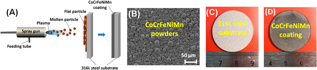
FIGURE 1. The whole procedure of preparation of CoCrFeNiMn HEA coatings by APS. (A) Schematic diagram of APS technique; (B) SEM morphology of the CoCrFeNiMn powders; (C) 316L steel substrate after sandblasting; (D) the macro morphology of CoCrFeNiMn HEA coatings prepared by APS.
Transient Thermal Shock Tests
The SEB (M) -100A vacuum electron beam bombardment furnace (Guilin Strong Numerical Control Vacuum Equipment Co., Ltd, China) was used in the transient thermal shock tests. In the operating mode, the vacuum level of electron beam bombardment furnace should be kept less than 1 × 10⁻² Pa, as shown in Figure 2A. In the bombardment furnace, the electrons were emitted from the electron gun and accelerated by the electric field, then the electrons bombard the cathode, which heated the cathode and generated the cathode rays.
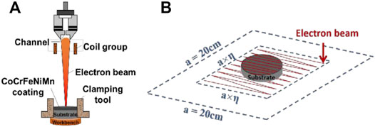
FIGURE 2. Transient thermal shock tests of CoCrFeNiMn HEA coatings. (A) Schematic diagram of transient thermal shock experiment by EB; (B) Scanning mode of the EB during the transient thermal shock tests.
Before the transient thermal shock tests, the as-sprayed HEA coatings were polished, named S0. During tests, the working voltage was 30 kV, and the action time was 200 ms. The beam spot diameter was set to be 5 mm, and the field frequency was 64 lines. The waveform frequency was set in rectangular 5 K. The power density was controlled by changing the beam current, and 6 batches of parallel transient thermal shock tests were carried out. The beam currents of 200 mA, 300 mA, 400 mA, 500 mA, 600 mA and 700 mA were selected, and the corresponding shocked coatings were named S1, S2, S3, S4, S5 and S6, respectively (Table 1). Then the EB power density and the power shocked on the coating sample during each test can be calculated with Equation 1:
where PD is the EB power density, P is the power of the electron gun, I is the EB current of the electron gun, U is the working voltage. a is the side length of the square area covered by the initial default of the EB device to complete the field frequency 64-line scan, and its value is 20 cm η is the scaling ratio for adjusting the range of the EB, which is set to be 30% in this experiment. S is the area of the square area covered by the EB to complete the field frequency scan of 64 lines, as shown in Figure 2B. The corresponding power density PD of the EB, and the power P0 shocked on the coatings during the experiment are shown in Table 1.
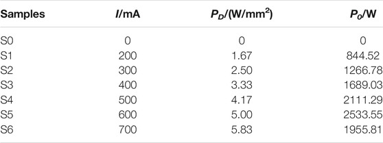
TABLE 1. Power density and power shocked on the coatings during the transient thermal shock tests. I: EB current, PD: EB power density, Po: power shocked on the coatings.
Characterizations of the Coating
Microstructures
The surface morphologies of the coatings were observed by the Apreo S Hi Vac high-resolution scanning electron microscope (SEM), which was produced by FEI, Czech. And the chemical composition was analyzed by the energy dispersive spectrometer (EDS). In addition, the phase structures of the HEA coatings were examined by the X’pertpro high-resolution X-ray diffractometer (XRD) produced by Philips in the Netherlands. Transmission electron microscopy (TEM) and selected area electron diffraction (SAED) were performed by using a ETEM (Thermo Fisher Scientific) microscope operated at an accelerating voltage of 300 kV. The TEM sample preparation has been performed by a duel beam FIB microscope, Strata 400S (FEI). After selection of the target area, a protection layer of Pt was deposited on the exposed target surface inside the FIB microscope. Then the target area was FIB ablated (30 kV) into a prism-shaped (10 μm length × 3 μm width × 5 μm depth). The sample was further mounted onto a Cu TEM grid and milled down-to a 80 nm thin lamella.
Microhardness Test
The microhardness of the coatings ware tested using the HVS1000A-XYT automatic microhardness tester produced by Laizhou Huayin Co., Ltd, China. During the tests, the square pyramid diamond indenter was pressed into the surface of the coating at room temperature. After holding for a period of time, the indenter was removed from the sample, leaving a nearly diamond-shaped indentation on the surface of the coating. By measuring the diagonal of the indentation length, substituting the diagonal length into Eq. 2, it can calculate the Vickers microhardness value of the coating:
where HV represents to the Vickers microhardness, α is the 136 included angle of the diamond pyramid edge, F is the loading force applied to the CoCrFeNiMn HEA coatings. And d is the length of the indentation diagonal.
The loading force in the experiment was 50 g, and the dwell time was 10 s. In order to accurately obtain the microhardness of the coating, 9 random points were selected in the form of a
The Weibull statistical distribution is widely used in reliability analysis and life testing in scientific research and engineering. In 1933, Rosin et al. firstly used the distribution for studying the distribution of scraps (Rosin and Rammler, 1933). The Weibull statistical distribution can be derived in different forms in different application scenarios. And in this study, two-parameter Weibull statistics were used to analyze the reliability of the microhardness data.
Results and Discussion
Microstructures and Composition Analysis
Figure 3 shows the SEM morphologies of the CoCrFeNiMn HEA coatings, including the as-sprayed sample S0, and the samples after transient thermal shock tests. It can be observed that the thickness of the as-sprayed HEA coatings by APS is between 300∼400 μm (Figure 3A). Though an obvious interface is appeared between the HEA coating and the 316L steel substrate, the HEA coating is closely bonded to the substrate (Figure 3B). Figure 3C shows the cross section of the as-sprayed coating, and it can be seen that there are two completely different phases in the HEA coating: a bright phase and a flocculent dark phase. This dark phase distribution can also be observed in the surface (Figure 3D), and its content is high, which was also found by previous studies (Xiao et al., 2020; Liao et al., 2021). Two different phases can be clearly observed on both the cross section and the surface of the coatings, indicating that the composition segregation happened in the HEA coatings. After transient thermal shock tests with different EB power density, the bright phase and flocculent dark phase remain in the HEA coating, and no obvious changes in the distribution of these two phases can be observed, as shown in Figures 3E–P, which indicates that the phase structures of the HEA coating are stable under transient thermal shock by EB. To identify the elemental content in the two phases, an EDS analysis was conducted on the coatings. And the corresponding chemical composition of the HEA coatings are shown in Table 2. The content of Co., Cr, Fe, and Ni in the coating was close to equal atomic percentage, while the content of Mn decreased significantly. This is mainly because manganese is easily volatile at high temperatures during the process of APS (Li et al., 2018; Xiao et al., 2020; Liao et al., 2021). In the bright phase, the Co., Fe, Cr and Ni are approximately close to the atomic ratio, and Mn is only ∼ 1 at. %. The oxygen content in the bright phase is relatively low compared with the dark phase. In the dark phase, however, the oxygen content is very high, ∼ 50 at. %. Thus, it can be inferred that the dark phase is the metal oxides, while the bright phase could be CoCrFeNi with a small amount of Mn. During the transient thermal shock tests, the flocculent dark phase of the metal oxides restricted the bright phase, resulting in the stability of the microstructures. Comparing the as-sprayed HEA coating surface (Figure 3D) with the HEA coating surfaces after transient thermal shock tests (Figures 3F, H, J, N, P), it can be found that there are some tiny micro cracks on the HEA coatings surface after tests. This could be ascribed to the induced high thermal stress. During transient thermal shock tests, the coating surface could reach a high temperature at a short time, and cooled down quickly. The difference in shrinkage between the bright phase and the dark phase caused a large stress concentration on the surface. When the stress in the surface layer exceeded the bond strength of the two phases, cracks would occur (Vandehaar et al., 1988).
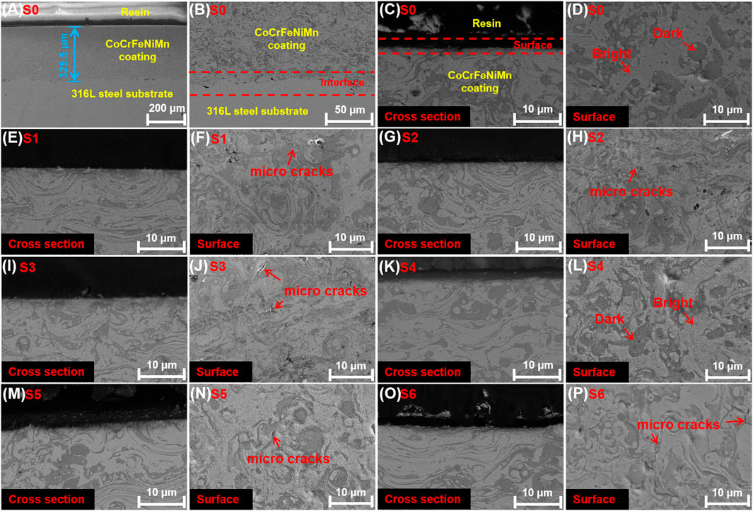
FIGURE 3. SEM morphologies of the CoCrFeNiMn HEA coatings(A–D) the as-sprayed coatings S0; (E, F) S1; (G, H) S2; (I, J) S3; (K, L) S4; (M, N) S5; and (O, P) S5.
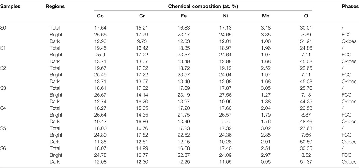
TABLE 2. Chemical compositions of different regions in the CoCrFeNiMn HEA coatings by EDS (at.%).
Figure 4 shows the XRD patterns of the CoCrFeNiMn HEA coatings. It can be observed that there are two phases in the coatings: an FCC phase and a metal oxides phase. Combining with the above EDS analysis results, it can be inferred that the bright phase of the coating is FCC solid solution structure, and the dark phase is the metal oxides phase. Both the FCC phase and the metal oxides remain stable under different transient thermal shock tests. However, the prominent diffraction peaks of the shocked coatings were slightly shifted to a higher angle, indicating the thermal stress was generated on the coating surface during the transient thermal shock tests, resulting in a smaller interplanar spacing (Vandehaar et al., 1988).
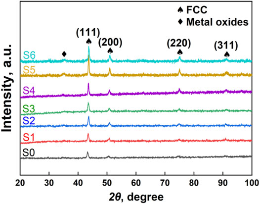
FIGURE 4. XRD patterns of the CoCrFeNiMn HEA coatings before and after transient thermal shock tests.
To further identify the detailed microstructure of the HEA coating, TEM was used to characterize and analyze the bright phase and the dark phase. The image in Figure 5A reveals that the bright phase is an FCC solid solution structure, and the grain size is ∼ 10–100 nm. And in Figure 5B, the flocculent regions (multi-component metal oxides) embedded in the bright matrix. It can be observed that these metal oxides are in nanometers. The flocculent regions appear darker as compared with the surrounding phase, indicating that these areas exhibit a lower average atomic number. The inset SAED shows the complex polycrystalline rings, which is mainly ascribed to the random orientation of the nano-multi-component metal oxides particles.
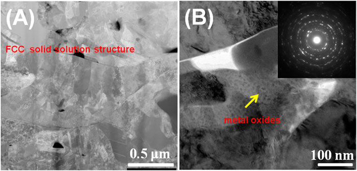
FIGURE 5. Microstructure analysis of the CoCrFeNiMn HEA coating by TEM. (A) Bright region showing an FCC structure, (B) Dark region showing a high density of nano-particles (metal oxides). The inset SAED indicating the diffraction rings of oxides.
Microhardness Stability
The microhardness average values of the CoCrFeNiMn HEA coatings are shown in Figure 6, ∼ 420 HV. It shows that the microhardness of the HEA coatings keeps stable as the power density of the transient thermal shock tests increases. Thus, it can infer that the transient thermal shocks by EB with a power density from 1.67 to 5.83 W/mm2 have little influence on the microhardness of the CoCrFeNiMn HEA coating. In fact, as above discussed, the two phase structure and contents of the HEA coatings remain stable during transient thermal shock, which could directly reflect on their mechanical properties. During the transient thermal shock tests, the bright phase (FCC structure) and the dark phase (metal oxides) in the HEA coatings kept almost unchanged, resulting in their microhardness stable.
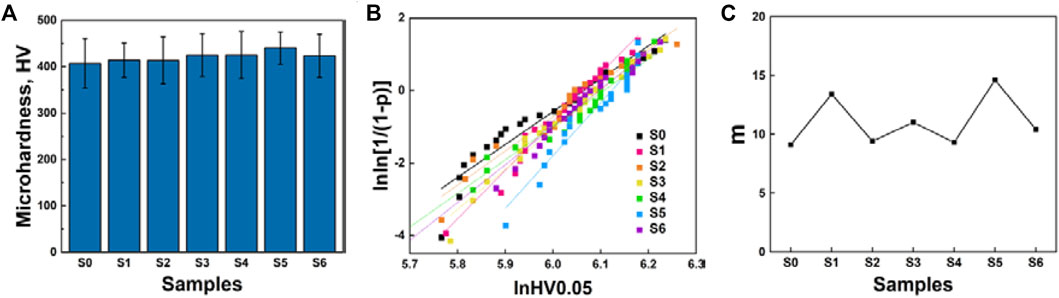
FIGURE 6. Microhardness of the coatings before and after transient thermal shock tests. (A) The average microhardness of the coatings; (B) Weibull plots of surface microhardness; (C) Weibull modulus of the different samples.
The nanoindentaion points with a
where n is the total number of samples for statistics, that is the total number of microhardness data in this study; i is the ordinal number obtained by arranging data from small to large; m is the shape parameter, also known as Weibull modulus, which reflects the dispersion of hardness data distribution; p represents the cumulative density function of probability; x is the measured value, which is Vickers hardness here. x0 is the eigenvalue, also known as the scale parameter. Although p can be written in a variety of expression, it is more accurate to use Eq. 4 to calculate p when the microhardness data of each coating sample is less than 50 (Bergman, 1984). The regression equation was used to perform linear fitting on the processed data to obtain the Weibull statistical distribution diagram, as shown in Figure 6B. The ordinate value of each data in Weibull statistical distribution is only related to the relative magnitude of the microhardness in all the measured hardness of the same sample, while the abscissa is determined by the hardness value. The Weibull modulus of the fitting line is shown in Figure 6C. According to Eq. 3, the Weibull modulus m is the slope of the fitting line. A greater value of m indicates the denser distribution of the data on the horizontal axis, and the higher reliability of the data. The m value of the thermal spraying coatings, due to the defects such as the pores or cracks generated by the spraying process, should be lower than that of the compact engineering ceramics which was ranging from 5 to 10 (Askeland et al., 2009; Ang and Berndt, 2014). However, in this study, the Weibull modulus m of the HEA coatings is between 9 ∼ 15. It can be concluded that the surface defects of CoCrFeNiMn HEA coatings, before or after transient thermal shock tests, have little influence on the microhardness of the coating surface.
To further study the difference of the FCC phase and the metal oxides phase, we tested the microhardness of the bright phase and the dark phase, respectively. After transient thermal shock tests with a power density of 3.33 W/mm2, the average microhardness of the FCC phase was ∼ 299.44 HV, which was significantly lower than the overall surface microhardness of ∼ 425.35 HV. This result demonstrated that the metal oxides phase had higher microhardness than the FCC phase, which improved the overall microhardness of the coating surface.
Conclusion
In summary, the CoCrFeNiMn HEA coatings with a thickness of 300–400 μm were successfully synthesized via APS technique, and a series of transient thermal shock tests with different power density were performed on the HEA coatings to explore its effects on the microstructures and mechanical properties. It was found that CoCrFeNiMn HEA coatings contained two main phases: an FCC solid solution phase and a metal oxides phase. These two phases remain stable in the HEA coatings after transient thermal shock tests by EB. A few tiny cracks appeared on the surface of the coating after transient thermal shock. In the HEA coatings, there was a lot of oxygen, but the Mn content became less. However, the other four elements of Co., Cr, Fe and Ni were approximately equal atomic ratio. The microhardness of the coating surface remained stable before and after transient thermal shock. Weibull statistics were used to analyze the reliability of the coating microhardness, and the Weibull modulus m was between 9 ∼ 15. The excellent transient thermal shock resistance makes it have service advantages in extreme environments, especially in the fields of the development of future nuclear or aerospace structural materials.
Data Availability Statement
The raw data supporting the conclusions of this article will be made available by the authors, without undue reservation.
Author Contributions
W-BL designed the research project; J-TL, S-WL, W-JH, and WZ characterized the alloys; J-TL, S-WL, and H-LZ analyzed the data; J-TL, S-WL, H-LZ, and W-BL wrote the paper.
Funding
This research was supported by the National Natural Science Foundation of China (Grant No. 51801128), Guangdong Basic and Applied Basic Research Foundation (Grant No. 2021A1515012278), Shenzhen Science and Technology Innovation Committee (Peacock Plan 827-000351), Natural Science Foundation of Shenzhen University (Grant No. 860-000002110212).
Conflict of Interest
The authors declare that the research was conducted in the absence of any commercial or financial relationships that could be construed as a potential conflict of interest.
Publisher’s Note
All claims expressed in this article are solely those of the authors and do not necessarily represent those of their affiliated organizations, or those of the publisher, the editors and the reviewers. Any product that may be evaluated in this article, orclaim that may be made by its manufacturer, is not guaranteed or endorsed by the publisher.
Acknowledgments
W-BL would like to acknowledge the technical support from the Instrumental Analysis Centre of Shenzhen University.
References
Aliyu, A., and Srivastava, C. (2019). Microstructure-Corrosion Property Correlation in Electrodeposited AlCrFeCoNiCu High Entropy Alloys-Graphene Oxide Composite Coatings. Thin Solid Films. 686, 137434. doi:10.1016/j.tsf.2019.137434
Ang, A. S. M., and Berndt, C. C. (2014). Investigating the Anisotropic Mechanical Properties of Plasma Sprayed Yttria-Stabilised Zirconia Coatings. Surf. Coat. Technology. 259, 551–559. doi:10.1016/j.surfcoat.2014.10.031
Ang, A. S. M., Berndt, C. C., Sesso, M. L., Anupam, A., S, P., Kottada, R. S., et al. (2014). Plasma-Sprayed High Entropy Alloys: Microstructure and Properties of AlCoCrFeNi and MnCoCrFeNi. Metall. Mat Trans. A. 46, 791–800. doi:10.1007/s11661-014-2644-z
Askeland, D. R., Fulay, P., and Bhattacharya, D. K. (2009). Essentials of Materials Science and Engineering. SI Edition. Stamford: Cengage Learning.
Bergman, B. (1984). On the Estimation of the Weibull Modulus. J. Mater. Sci. Lett. 3 (8), 689–692. doi:10.1007/BF00719924
Cantor, B., Chang, I. T. H., Knight, P., and Vincent, A. J. B. (2004). Microstructural Development in Equiatomic Multicomponent Alloys. Mater. Sci. Eng. A. 375-377, 213–218213. doi:10.1016/j.msea.2003.10.257
Chen, H.-Y., Luo, L.-M., Zan, X., Xu, Q., Tokunaga, K., Liu, J.-Q., et al. (2018). Transient Thermal Shock Behavior of W-Zr/Sc2O3 Composites Prepared via Spark Plasma Sintering. Fusion Eng. Des. 126, 44–50. doi:10.1016/j.fusengdes.2017.11.012
Chen, M., Wang, H., Jin, H., Pan, X., and Jin, Z. (2016). Transient Thermal Shock Behavior Simulation of Porous Silicon Nitride Ceramics. Ceramics Int. 42 (2), 3130–3137. doi:10.1016/j.ceramint.2015.10.102
Chen, Y. Y., Duval, T., Hung, U. D., Yeh, J. W., and Shih, H. C. (2005). Microstructure and Electrochemical Properties of High Entropy Alloys-A Comparison With Type-304 Stainless Steel. Corrosion Sci. 47, 2257–2279. doi:10.1016/j.corsci.2004.11.008
Ding, Z. Y., Cao, B. X., Luan, J. H., and Jiao, Z. B. (2021). Synergistic Effects of Al and Ti on the Oxidation Behaviour and Mechanical Properties of L12-Strengthened FeCoCrNi High-Entropy Alloys. Corrosion Sci. 184, 109365. doi:10.1016/j.corsci.2021.109365
Fan, L., Yang, T., Zhao, Y., Luan, J., Zhou, G., Wang, H., et al. (2020). Ultrahigh Strength and Ductility in Newly Developed Materials With Coherent Nanolamellar Architectures. Nat. Commun. 11, 6240. doi:10.1038/s41467-020-20109-z
Fan, X., Wang, H., Niu, M., Zhang, D., Zhou, J., and Fan, J. (2018). Experiments and Transient Finite Element Simulation of γ-Y2Si2O7/B2O3-Al2O3-SiO2 Glass Coating on Porous Si3N4 Substrate under thermal Shock. Ceramics Int. 44 (4), 4072–4079. doi:10.1016/j.ceramint.2017.11.205
Fu, Y., Hu, J., Zhao, W., Peng, F., Huo, W., and Cao, X. (2020). Microstructure Modification and Corrosion Improvement of AISI1045 Steel Induced by Pseudospark Electron Beam Treatment. Nucl. Instr. Methods Phys. Res. Section B: Beam Interactions Mater. Atoms. 469, 10–18. doi:10.1016/j.nimb.2020.02.033
Gludovatz, B., Hohenwarter, A., Catoor, D., Chang, E. H., George, E. P., and Ritchie, R. O. (2014). A Fracture-Resistant High-Entropy Alloy for Cryogenic Applications. Science. 345 (6201), 1153–1158. doi:10.1126/science.1254581
Hsu, C.-Y., Yeh, J.-W., Chen, S.-K., and Shun, T.-T. (2004). Wear Resistance and High-Temperature Compression Strength of Fcc CuCoNiCrAl0.5Fe alloy With boron Addition. Metall. Mat Trans. A. 35, 1465–1469. doi:10.1007/s11661-004-0254-x
Hsu, W.-L., Yang, Y.-C., Chen, C.-Y., and Yeh, J.-W. (2017). Thermal Sprayed High-Entropy NiCo 0.6 Fe 0.2 Cr 1.5 SiAlTi 0.2 Coating With Improved Mechanical Properties and Oxidation Resistance. Intermetallics. 89, 105–110. doi:10.1016/j.intermet.2017.05.015
Huo, W., Liu, X., Tan, S., Fang, F., Xie, Z., Shang, J., et al. (2018). Ultrahigh Hardness and High Electrical Resistivity in Nano-Twinned, Nanocrystalline High-Entropy alloy Films. Appl. Surf. Sci. 439, 222–225. doi:10.1016/j.apsusc.2018.01.050
Lei, Z., Liu, X., Wu, Y., Wang, H., Jiang, S., Wang, S., et al. (2018). Enhanced Strength and Ductility in a High-Entropy Alloy via Ordered Oxygen Complexes. Nature. 563, 546–550. doi:10.1038/s41586-018-0685-y
Li, C. (2019). Microstructure and High-Temperature Oxidation Properties of NiCoCrAlYSiHf Coating by Arc Ion Plating Under High Current Pulsed Electron Beam. Zhenjiang: Jiangsu University.
Li, R., Niu, P., Yuan, T., Cao, P., Chen, C., and Zhou, K. (2018). Selective Laser Melting of an Equiatomic CoCrFeMnNi High-Entropy alloy: Processability, Non-Equilibrium Microstructure and Mechanical Property. J. Alloys Compounds. 746, 125–134. doi:10.1016/j.jallcom.2018.02.298
Li, Y. (2011). Surface Stress Characteristics and Microstructure of Metal Materials in Different Systems Induced by High Current Pulsed Electron Beam. Zhenjiang: Jiangsu University.
Li, Z., Pradeep, K. G., Deng, Y., Raabe, D., and Tasan, C. C. (2016). Metastable High-Entropy Dual-phase Alloys Overcome the Strength-Ductility Trade-Off. Nature. 534, 227–230. doi:10.1038/nature17981
Liao, W.-B., Wu, Z.-X., Lu, W., He, M., WangGuo, T. Z. X., Guo, Z., et al. (2021). Microstructures and Mechanical Properties of CoCrFeNiMn High-Entropy Alloy Coatings by Detonation Spraying. Intermetallics. 132 (1), 107138. doi:10.1016/j.intermet.2021.107138
Liao, W., Lan, S., Gao, L., Zhang, H., Xu, S., Song, J., et al. (2017). Nanocrystalline High-Entropy alloy (CoCrFeNiAl0.3) Thin-Film Coating by Magnetron Sputtering. Thin Solid Films. 638, 383–388. doi:10.1016/j.tsf.2017.08.006
Liu, W. H., Wu, Y., He, J. Y., Nieh, T. G., and Lu, Z. P. (2013). Grain Growth and the Hall-Petch Relationship in a High-Entropy FeCrNiCoMn Alloy. Scripta Materialia. 68, 526–529. doi:10.1016/j.scriptamat.2012.12.002
Lu, T.-W., Feng, C.-S., Wang, Z., Liao, K.-W., Liu, Z.-Y., Xie, Y.-Z., et al. (2019). Microstructures and Mechanical Properties of CoCrFeNiAl0.3 High-Entropy Alloy Thin Films by Pulsed Laser Deposition. Appl. Surf. Sci. 494, 72–79. doi:10.1016/j.apsusc.2019.07.186
Mu, Y. K., Jia, Y. D., Xu, L., Jia, Y. F., Tan, X. H., Yi, J., et al. (2019). Nano Oxides Reinforced High-Entropy alloy Coatings Synthesized by Atmospheric Plasma Spraying. Mater. Res. Lett. 7 (8), 312–319. doi:10.1080/21663831.2019.1604443
Nagase, T., Rack, P. D., Noh, J. H., and Egami, T. (2015). In-Situ TEM Observation of Structural Changes in Nano-Crystalline CoCrCuFeNi Multicomponent High-Entropy alloy (HEA) Under Fast Electron Irradiation by High Voltage Electron Microscopy (HVEM). Intermetallics. 59, 32–42. doi:10.1016/j.intermet.2014.12.007
Otto, F., Dlouhý, A., Somsen, C., Bei, H., EggelerGeorge, G. E. P., and George, E. P. (2013). The Influences of Temperature and Microstructure on the Tensile Properties of a CoCrFeMnNi High-Entropy alloy. Acta Materialia. 61, 5743–5755. doi:10.1016/j.actamat.2013.06.018
Park, H. J., Na, Y. S., Hong, S. H., Kim, J. T., Kim, Y. S., Lim, K. R., et al. (2016). Phase Evolution, Microstructure and Mechanical Properties of Equi-Atomic Substituted TiZrHfNiCu and TiZrHfNiCuM (M = Co, Nb) High-Entropy Alloys. Met. Mater. Int. 22, 551–556. doi:10.1007/s12540-016-6034-5
Rosin, P., and Rammler, E. (1933). The Laws Governing the Fineness of Powdered Coal. J. Inst. Fuel. 7, 29–36.
Senkov, O. N., Wilks, G. B., Scott, J. M., and Miracle, D. B. (2011). Mechanical Properties of Nb25Mo25Ta25W25 and V20Nb20Mo20Ta20W20 Refractory High Entropy Alloys. Intermetallics. 19, 698–706. doi:10.1016/j.intermet.2011.01.004
Vandehaar, E., Malian, P. A., Baldwin, M., Liang, Y., and Shi, C. X. (1988). Laser Cladding of Thermal Barrier Coatings. Surf. Eng. 4 (2), 159–172. doi:10.1179/sur.1988.4.2.159
Wang, H., Chen, D., An, X., Zhang, Y., Sun, S., Tian, Y., et al. (2021). Deformation-induced Crystalline-To-Amorphous Phase Transformation in a CrMnFeCoNi High-Entropy alloy. Sci. Adv. 7 (14), eabe3105. doi:10.1126/sciadv.abe3105
Xia, S. Q., Yang, X., Yang, T. F., Liu, S., and Zhang, Y. (2015). Irradiation Resistance in Al X CoCrFeNi High Entropy Alloys. Jom. 67 (10), 2340–2344. doi:10.1007/s11837-015-1568-4
Xiao, J.-K., Tan, H., Wu, Y.-Q., Chen, J., and Zhang, C. (2020). Microstructure and Wear Behavior of FeCoNiCrMn High Entropy Alloy Coating Deposited by Plasma Spraying. Surf. Coat. Technology. 385, 125430. doi:10.1016/j.surfcoat.2020.125430
Yang, T., Zhao, Y. L., Tong, Y., Jiao, Z. B., Wei, J., Cai, J. X., et al. (2018). Multicomponent Intermetallic Nanoparticles and Superb Mechanical Behaviors of Complex Alloys. Science. 362, 933–937. doi:10.1126/science.aas8815
Yeh, J.-W., Chen, S.-K., Lin, S.-J., Gan, J.-Y., Chin, T.-S., Shun, T.-T., et al. (2004). Nanostructured High-Entropy Alloys With Multiple Principal Elements: Novel Alloy Design Concepts and Outcomes. Adv. Eng. Mater. 6, 299–303. doi:10.1002/adem.200300567
Zhang, H., Pan, Y., and He, Y.-Z. (2011). Synthesis and Characterization of FeCoNiCrCu High-Entropy Alloy Coating by Laser Cladding. Mater. Des. 32 (4), 1910–1915. doi:10.1016/j.matdes.2010.12.001
Zhang, Y., Zuo, T. T., Tang, Z., Gao, M. C., Dahmen, K. A., Liaw, P. K., et al. (2014). Microstructures and Properties of High-Entropy Alloys. Prog. Mater. Sci. 61, 1–93. doi:10.1016/j.pmatsci.2013.10.001
Keywords: high-entropy alloy, coatings, transient thermal shock, microhardness, weibull statistics
Citation: Liu J-, Liu S-, Zheng H-, Huang W-, Zhao W and Liao W- (2021) Effects of Transient Thermal Shock on the Microstructure and Mechanical Properties of CoCrFeNiMn High-Entropy Alloy Coatings. Front. Mater. 8:805296. doi: 10.3389/fmats.2021.805296
Received: 30 October 2021; Accepted: 25 November 2021;
Published: 21 December 2021.
Edited by:
Zengbao Jiao, Hong Kong Polytechnic University, Hong Kong SAR, ChinaReviewed by:
Lei Zhifeng, Hunan University, ChinaZhiyi Ding, University of Shanghai for Science and Technology, China
Copyright © 2021 Liu, Liu, Zheng, Huang, Zhao and Liao. This is an open-access article distributed under the terms of the Creative Commons Attribution License (CC BY). The use, distribution or reproduction in other forums is permitted, provided the original author(s) and the copyright owner(s) are credited and that the original publication in this journal is cited, in accordance with accepted academic practice. No use, distribution or reproduction is permitted which does not comply with these terms.
*Correspondence: Wei-Bing Liao, bGlhb3diQHN6dS5lZHUuY24=
†These authors have contributed equally to this work and share first authorship