 Minjuan He1
 Lina Zhou
 Xiaofeng Sun
95% of researchers rate our articles as excellent or good
Learn more about the work of our research integrity team to safeguard the quality of each article we publish.
Find out more
ORIGINAL RESEARCH article
Front. Mater. , 10 January 2022
Sec. Structural Materials
Volume 8 - 2021 | https://doi.org/10.3389/fmats.2021.802249
This article is part of the Research Topic Multi-Scale Investigation on Fiber-Reinforced Composite Materials: From Structural Design, Property Characterization to Engineering Applications View all 9 articles
The fiber-reinforced polymer is one kind of composite material made of synthetic fiber and resin, which has attracted research interests for the reinforcement of timber elements. In this study, 18 glued-laminated (glulam) beams, unreinforced or reinforced with internally embedded carbon fiber–reinforced polymer (CFRP) sheets, were tested under four-point bending loads. For the reinforced glulam beams, the influences of the strengthening ratio, the modulus of elasticity of the CFRP, and the CFRP arrangement on their bending performance were experimentally investigated. Subsequently, a finite element model developed was verified with the experimental results; furthermore, a general theoretical model considering the typical tensile failure mode was employed to predict the bending–resisting capacities of the reinforced glulam beams. It is found that the reinforced glulam beams are featured with relatively ductile bending failure, compared to the brittle tensile failure of the unreinforced ones. Besides, the compressive properties of the uppermost grain of the glulam can be fully utilized in the CFRP-reinforced beams. For the beams with a 0.040% strengthening ratio, the bending–resisting capacity and the maximum deflection can be enhanced approximately by 6.51 and 12.02%, respectively. The difference between the experimental results and the numerical results and that between the experimental results and analytical results are within 20 and 10%, respectively.
The mechanical properties of timber elements can be significantly influenced by the presence of natural defects (e.g., knots and cracks). For structural applications, timber structures can be further weakened in unfavorable environments and exhibit aging during long-term use. Therefore, for the historical timber buildings, their key structural components commonly require repairing and reinforcing in modern times; besides, for the modern timber buildings, the increasing demands for both higher strength and stiffness of their structural members would also facilitate the application of the reinforcing technology. In the past decades, timber members reinforced with steel materials have been widely studied (McConnell et al., 2014; Wei et al., 2020; Zhang et al., 2020), whereas their applications were limited due to the relatively high density and poor corrosion resistance of the steel reinforcement materials. Recently, an increasing number of investigations have been conducted on reinforcing timber structures with fiber-reinforced polymer (FRP), owing to its excellent resistance to corrosion, high strength-to-weight ratio, and the diversity of FRP products (Sun et al., 2020). The FRP is a composite material that consists of synthetic fiber as enhancement and resin as an adhesive. The common synthetic fiber used in timber structures includes glass fiber–reinforced polymer (GFRP), carbon fiber–reinforced polymer (CFRP), basalt fiber–reinforced polymer (BFRP), and aramid fiber–reinforced polymer (AFRP). The adhesion of resin that is always thermosetting can ensure the integrity of both the FRPs and the timber.
Since 1990s, some investigations have been focused on the mechanical properties of the FRP-reinforced timber beams. In 1992, Plevris and Triantafillou (1992) investigated wood elements bonded with external CFRP. The analytical results based on the proposed model of the reinforced wood members under both bending and axial forces agreed well with the experimental results. For plate-shaped FRP (e.g., plates and sheets), the externally bonding method (EBM) has been widely used due to the convenience of application. Meanwhile, glulam beams also enable the plate-shaped FRP to be embedded horizontally or vertically in the laminations of timber during the gluing process. Lu et al. (2015) tested the bending performance of the glulam beams reinforced with CFRP plates that were arranged vertically in the bottommost laminations of the timber beams by near surface mounted (NSM) techniques. Significant enhancement of the bending strength and stiffness was achieved by using the CFRP as reinforcement, and the pseudo-ductile behavior was observed in the reinforced glulam beams. Corradi et al. (2017) conducted bending tests on totally 221 wood beams reinforced with FRP sheets and found that the variability of their bending strength was much less than that of the traditional glulam beams. Gómez et al. (2019) observed that timber beams reinforced by FRP sheets on their lateral sides exhibited similar bending properties, compared to those reinforced by the FRP sheets with the same volume fraction at the bottom. Vahedian et al. (2019) tested 8 full-scale glulam beams consisting of both unreinforced beams and those reinforced with externally bonded CFRP sheets. Bending performance of the glulam beams was enhanced remarkably with an increase of the width, the length, or the bonding thickness of FRP.
For bar-shaped FRP (e.g., bars, rods, and cords), the fabrication procedures always require slotting on the timber surface. Johnsson et al. (2007) studied pultruded rectangular CFRP rods as the reinforcement of glulam beams and investigated the influence of the anchoring length of CFRP rods on the bending performance of beams. A theoretical model was proposed, and it presented great predictions in comparison to the experimental results. Raftery and Whelan (2014) found that compared to the square grooves, the circular ones for the GFRP 61 rods exhibited more significant effect for enhancing the bending properties of the glulam beams. Fossetti et al. (2015) performed bending tests on timber beams with various dimensions, different glued-in FRP (i.e., CFRP cords, GFRP cords, and BFRP rods), and two kinds of adhesives (i.e., melamine glue and epoxy resin). It was observed that the reinforcement of FRP cords is a potential alternative to pultruded bars. Rajczyk and Jonczyk (2019) tested the glulam beams reinforced by the BFRP rods with various diameters or arrangement at the cross section of the beams. The experimental load-resisting capacities showed little correlations with the area ratio between the FRP and the glulam for different series of tested reinforced glulam beams. Lv et al. (2019) tested the pure laminated bamboo beam and the laminated bamboo beam reinforced with both non-prestressed and prestressed BFRP bar. It was found that the prestressed beams did not exhibit an enhancement in the ultimate load-resisting capacity compared to the non-prestressed beams.
Theoretical analysis methods generally consider a uniaxial constitutive model for both the glulam and the FRP along the longitudinal direction to predict the bending performance of FRP-reinforced glulam beams. The Bazan–Buchanan law (Bazan, 1980; Buchanan, 1990) was employed to reflect the longitudinal stress–strain relationship of the wood fibers in many studies (Plevris and Triantafillou, 1992; Fiorelli and Dias, 2011; Yang et al., 2016; Vahedian et al., 2019). Fiorelli and Dias (2011) employed the transformed cross section method to calculate the bending stiffness of the reinforced glulam beams and then adopted the Bazan–Buchanan law to calculate their bending strength. The model exhibited a good agreement between the experimental and theoretical results. In the study conducted by Lindyberg and Daghber (2012), a nonlinear-reinforced laminated model (i.e., the ReLAM model) was established and examined by 90 FRP-reinforced glulam beams. Results show that satisfactory load–deflection curves could be achieved via iterative procedures of the ReLAM model. Yang et al. (2016) proposed a theoretical method that could consider the size effect of the glulam and the influence of the stress distribution. A modification factor that is higher than the one used by Gentile et al. (2002) was employed in Yang’s model to consider the increase of the ultimate tensile strain in the reinforced beams.
Using the FEM program, more efficient evaluation of reinforced glulam beams could be obtained. The FEM model proposed by Raftery and Harte (2013) adopted nonlinear geometry and an anisotropic plasticity model for the compressive glulam. Acceptable accuracy of prediction on the bending performance could be obtained compared to the experimental results of the reinforced beams with or without sacrificial laminations. Two numerical models specifying elasticity and elastoplasticity for timber were proposed by Nowak et al. (2013) to predict the bending performance of timber beams reinforced by CFRP strips. The numerical load–displacement curves from numerical modeling analysis were consistent with the experimental results within the elastic stage of the timber. To analyze the bending performance of glulam beams reinforced with CFRP plates, Glišović et al. (2017) established FE models of the glulam beams reinforced with bonded CFRP plates externally or internally and the ones without reinforcement. In these models, timber was simulated as an orthotropic material, and a modification factor was employed for its tensile strength under the bending condition, whereby a good agreement of the nonlinear performance could be obtained between the numerical and experimental results.
As aforementioned, bonding FRP sheets externally is convenient for repairing or reinforcing the timber element; however, it would cause an esthetic issue, which does not coordinate with the situation that the FRP sheets are commonly adopted as an initial reinforcement for the relatively new buildings. Meanwhile, it is found that the investigations on the timber beams reinforced with the internal FRP sheets are much limited compared to those on the timber beams reinforced with the external FRP sheets. Besides, a parametric study on the internally FRP-reinforced beams was generally conducted based on the theoretical model rather than the tests or the numerical model. Therefore, this study was conducted for comprehending the enhancement efficiency of the bending performance of the glulam beams reinforced by using the internal FRP sheets.
In this article, 18 glulam beams, unreinforced and reinforced with internally embedded CFRP sheets, were studied based on the four-point bending tests. Parametric analysis was carried out for investigating the influences of the reinforcement ratios, the CFRP strength, and the arrangement of CFRP sheets on the bending performance of glulam beams. A finite element model was developed to simulate the performance of CFRP-reinforced beams via commercial program ABAQUS. Meanwhile, a theoretical model considering the typical failure mode of the CFRP-reinforced glulam beams was used to predict their bending performance.
In this study, glulam was manufactured with the Douglas fir. The mechanical properties of the glulam were tested according to ASTM D143-14 (2014) and GB/T 15777-2017 (2017), and listed in Table 1. The density and moisture content of the Douglas fir were tested according to GB/T 1931-2009 (2009) and GB/T 1933-2009 (2009). An average density of 527.83 kg/m3 with a coefficient of variation (COV) of 6.10% was obtained; meanwhile, the average moisture content was 10.46% with a COV of 4.68%.
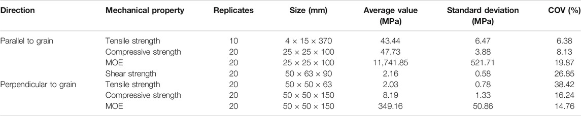
TABLE 1. Mechanical properties of the glulam.
There were two types of CFRP sheets used as reinforcement for the glulam beams. The tensile properties of the CFRP sheets were obtained based on the tests conducted by the manufacturer according to GB 50728-2011 (2011). The experimental results are listed in Table 2, where H and L represent the CFRP with an MOE of 2.35 × 10⁵ MPa and 2.04 × 10⁵ MPa, respectively. The thickness and the width of both CFRP sheets were 0.167 and 100 mm, respectively.
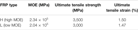
TABLE 2. Tensile properties of the FRP sheet.
A single-component polyurethane adhesive (PU adhesive) was employed for gluing Douglas fir laminations together along the same orientation. Based on a pull-out test, the bonding performance of the adhesive was examined. In the pull-out test, axial tension was applied to a CFRP sheet bonded between two Douglas fir blocks by using the identical PU adhesive. The tensile failure occurred in the CFRP sheets without delamination occurring between the CFRP and the blocks. It proved that PU adhesive was valid and suitable for manufacturing CFRP-reinforced glulam beams in this study.
Six groups of 18 glulam beams were tested based on a four-point bending test configuration, as shown in Figure 1. The specimen details are listed in Table 3. The tested glulam beams consisted of nine layers of Douglas fir laminations with a cross-sectional dimension of 140 mm × 33 mm or 120 mm × 33 mm. The length of Douglas fir laminations was 3,000 mm. For the reinforced beams, 3,000-mm-length CFRP sheets were embedded horizontally on the tensile side of the beams. CFRP-reinforced glulam beams were fabricated based on the following procedures: 1) preparation of laminations (e.g., drying, grading, planning, and surface cleaning); 2) fixing CFRP sheets on the designated lamination; 3) gluing, pressing, and conditioning the beam specimens; and 4) planning and sanding the surface of beams to remove residual adhesive when the curing strength was reached. An identical 300-mm height was obtained approximately for the cross section of both unreinforced and reinforced glulam beams. The thickness of the FRP layer was not counted. Two groups of unreinforced glulam beams were employed as benchmark specimens in this study, as shown in Figure 1. Other four groups of CFRP-reinforced glulam beams were designed to investigate the influences of the CFRP strengthening ratio, the CFRP MOE, and the CFRP arrangement on the bending performance of reinforced glulam beams. The CFRP strengthening ratio is calculated as the ratio of the cross-sectional area of the CFRP sheet to that of the glulam beam. For the label of the specimens, W and N represent the 140-mm-width specimens and the 120-mm-width specimens, respectively; H and L represent the specimens reinforced by a CFRP with an MOE of 2.35 × 10⁵ MPa and 2.04 × 10⁵ MPa, respectively. The numbers from 1 to 3 were used to label the replicates in each group.
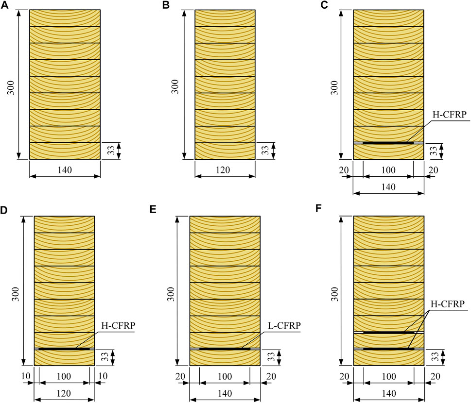
FIGURE 1. Cross sections of specimens: (A) group W; (B) group N; (C) group WH; (D) group NH; (E) group WL; and (F) group WH+H.
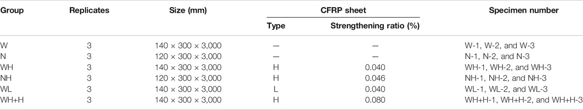
TABLE 3. Information of specimens.
The four-point bending test setup is shown in Figure 2. The glulam beams were simply supported with a net span of 2,700 mm and were loaded at two-thirds of the points. Three linear variable differential transducers (LVDTs) were used to measure the displacement of the beams, in which two of them were placed at the top of the beam where the two simple supports were located underneath and the other one was placed at the mid-span of the glulam beams. Five equally spaced strain gauges were mounted on the lateral side of one glulam beam of each group to record the flexural deformation of its cross section. All the bending tests were conducted with a 500-kN hydraulic actuator. A preliminary 5-kN preload was applied and maintained to the glulam beams for around 5 min; subsequently, a vertical loading with a displacement-based loading rate of 4 mm/min was applied to the glulam beams until failure occurred.

FIGURE 2. Four-point bending test setup.
For all the specimens, the bending failure occurred due to the fracture of the bottommost lamination in the pure bending area. Overall, all the bending failure belongs to a brittle failure mode, whereas some slight distinctions existed in the specific destruction phenomena between unreinforced glulam beams and CFRP-reinforced glulam beams.
For unreinforced beams, that is, the benchmark groups (group W and group N), no obvious damage occurred on the surface of the bending specimens during the initial loading process. When approaching the failure load, continuous cracking noise was heard which was immediately followed by a sudden failure of the whole beam. Mostly, the failure was caused by the brittle fracture of the knots existing at the bottom of the specimens, as shown in Figure 3A. Overall, one preliminary crack was developed originally from the fractured knots, and then was propagated diagonally upward along the timber grain, causing the glulam peeling. Furthermore, another crack development pattern was observed in the specimen N-2, as shown in Figure 3B. It is characterized by a longitudinal continuous crack formed preliminarily along the centerline of the bottom of the glulam, and then the crack is propagated, forming a final fracture zone in the bending specimens.
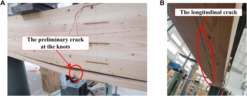
FIGURE 3. Bending failure of unreinforced beams: (A) crack at knots and (B) longitudinal crack.
For the CFRP-reinforced glulam beams in the groups of WH, NH, WL, and WH+H, a preliminary crack formed at the bottom of the pure bending area of the reinforced specimens, as shown in Figures 4A–C. During the loading process, the crack propagated at a slower speed until the bending failure, compared to the unreinforced beams. Meanwhile, for the bending specimens in group WH+H with the highest strengthening ratio, the outermost wood fibers on the compressive side of the cross sections wrinkled evidently (Figure 4D). In the specimen WH+H-1, the CFRP sheets were damaged in the form of out-of-plane tearing (Figure 4E) most likely due to the out-of-plane effect of timber peeling or being pierced by the edge fractured timber. During the bending test of one CFRP-reinforced glulam beam, the tearing failure of the CFRP sheet occurred subsequently after the severe fracture was observed in the neighboring timber lamination. It means that the loss of the bending capacity of the reinforced glulam beam actually originated from the tensile failure of the bottommost lamination. Since almost no debonding failure was observed in the adhesive layer before the failure of the reinforced beams, it indicates that little slip occurred between the FRP sheet and the timber laminations.
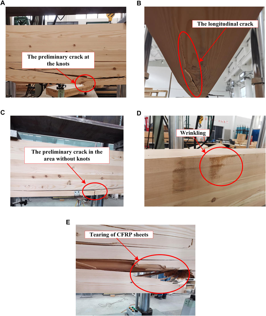
FIGURE 4. Bending failure of reinforced beams: (A) crack at knots; (B) longitudinal crack; (C) crack in the area without knots; (D) wrinkling on the compressive side of beam in group WH+H; and (E) tearing of the CFRP sheets.
It was revealed that the unpredictable dominant fracture on the tensile side of the glulam cross section prevented unreinforced beams from ductility behavior, resulting in an overall brittle damage mode, whereas the addition of the CFRP sheets could mitigate the brittle damages featured by a preliminary crack from the knots. For instance, in the CFRP-reinforced specimens of WH-1, WH-2, NH-3, and WH+H-2, the preliminary crack was propagated originally from an area without knots, as shown in Figure 4C. The wrinkling of the timber fibers indicates that the compressive resistance of the glulam in the reinforced specimens can be more fully utilized than that in the unreinforced specimens. It can be inferred that the failure mode of the specimens would be transformed from a brittle tensile failure to a relatively ductile compressive failure when increasing the CFRP strengthening ratio.
The load–deflection curves of all the specimens are shown in Figure 5. The load dropped dramatically once the ultimate loading-resisting capacity was reached, indicating that a brittle failure occurred in the bending specimens. Only slight distinction can be identified in the load–deflection curves of the three replicates per group, which indicates a relatively stable bending performance of the beams tested in this project.
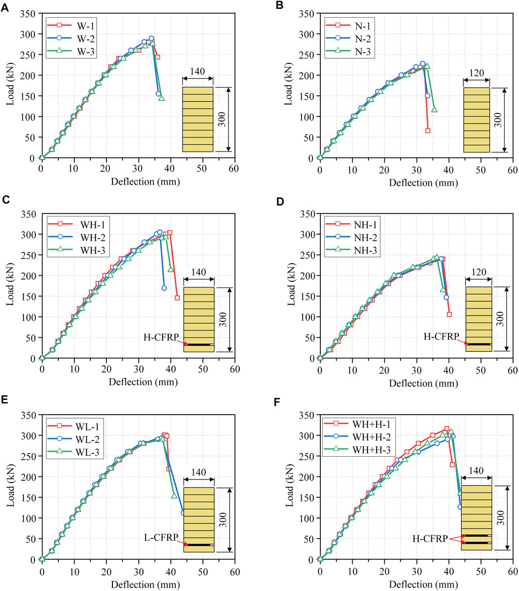
FIGURE 5. Load–deflection curves: (A) group W; (B) group N; (C) group WH; (D) group NH; (E) group WL; and (F) group WH+H.
The mechanical properties of glulam beams are listed in Table 4, in which, Fu represents the ultimate load-resisting capacity, Mu represents the ultimate bending-resisting moment, and Du represents the maximum deflection. By comparing the performance parameters between the unreinforced specimens and the CFRP-reinforced specimens with identical cross-sectional dimensions, the increasing ratio for each property was calculated per group. The apparent bending stiffness EappI was calculated based on Eq. 1 according to ASTM D198-15 (2015), which was corresponding to the apparent MOE Eapp, in which l0 is the net span of beams; F1 and F2 are equal to 0.1Fu and 0.4Fu, respectively; D1 and D2 are the deflections corresponding to F1 and F2, respectively.
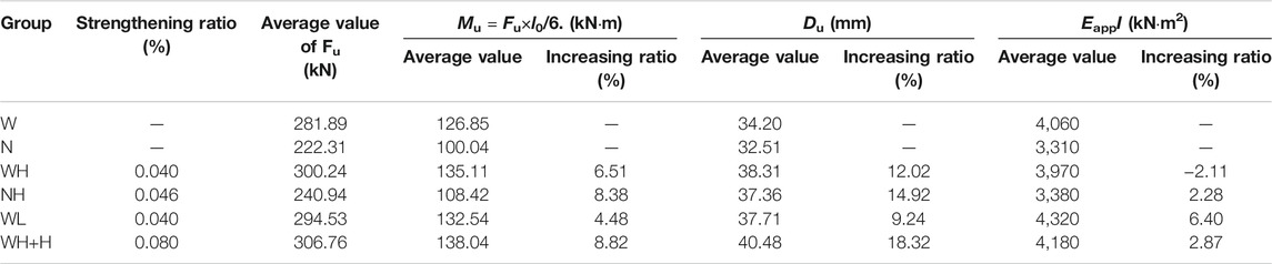
TABLE 4. Mechanical properties of glulam beams.
As listed in Table 4, compared to the unreinforced specimens, the Mu of the reinforced specimens was enhanced with a range from 4.48 to 8.82%, whereas their maximum deflection Du was enhanced more significantly with a range from 9.24 to 18.32%. The strengthening ratio was adopted within the range from 0.1 to 2.0% in the relative references (Raftery and Whelan, 2014; Yang et al., 2016; Gómez et al., 2019). In contrast, the bending capacity Mu of the CFPR-reinforced beams was not significantly enhanced, due to the relatively small CFRP strengthening ratio adopted within the range from 0.04 to 0.08% in the study. Compared to the unreinforced specimens, the increasing ratios of the EappI for the groups of WH, NH, and WH+H are less than 3%. It indicates that the addition of the CFRP sheets has little enhancement for the EappI of the glulam beams. Similar findings were reported by Yang et al. (2016). The difference between the increasing ratio of the Mu and that of the EappI can be attributed to the higher COV of timber MOE than that of the timber parallel-to-grain strength. Besides, as shown in Table 1, the negatively increasing ratio (i.e., −2.11%) of the EappI might also indicate that a significant variability exists for the timber MOE, resulting into the reduction of the EappI. Besides, for the specimens reinforced by the H-CFRP in the groups of WH, NH, and WH+H, the increasing ratio of the Mu or that of the Du can be enhanced with an increase of the CFRP strengthening ratio, which indicates that more wood fibers on the compressive side of the bending specimen were yielded.
For the influence of the MOE of the CFRP sheets on the bending performance of glulam beams, compared to the unreinforced specimens, the Mu and the Du of the specimens reinforced with the H-CFRP in group WH were increased by 6.51 and 12.02%, respectively, whereas the Mu and the Du of those reinforced with the L-CFRP in group WL were only increased by 4.48 and 9.24%, respectively. It indicates that the bending performance of the glulam beams can be enhanced more significantly when using the reinforcement of the CFRP sheets with a higher MOE. Such a conclusion is based on the condition that no premature failure of the CFRP or no slip failure between the glulam and the CFRP layer occurred during the bending tests.
For the influence of the CFRP arrangement on the bending performance of glulam beams, the Mu and the Du of the specimens reinforced with two layers of CFRP in group WH+H were 0.97 kN·m higher and 2.17 mm larger than those of the specimens reinforced with one layer of CFRP in group WH, respectively. Although the strengthening ratio of the specimens in group WH+H is twice that of the specimens in group WH, the increasing ratios of Mu or the Du were not doubled. It is because that the tensile strain of the CFRP sheet is reduced with an increase of the distance from the bottom of the beam to the position that the CFRP is arranged in; therefore, arranging the CFRP sheet higher from the bottom of the beam would result in a less enhancement of the glulam bending performance, compared to arranging it more close to the bottom of the beam.
By taking one bending specimen from group W and another from group WH+H as examples, the load–strain curves and the strain profile of the two specimens are plotted in Figure 6. The maximum strains existing at the top or bottom fibers of the cross section of the beams were obtained from the bending tests, as listed in Table 5. It should be noted that the de-lamination failure occurred in the specimens of group N, which brought difficulties for measuring their cross-sectional maximum strains; therefore, the maximum strains of the specimens in group N are not listed in Table 5.
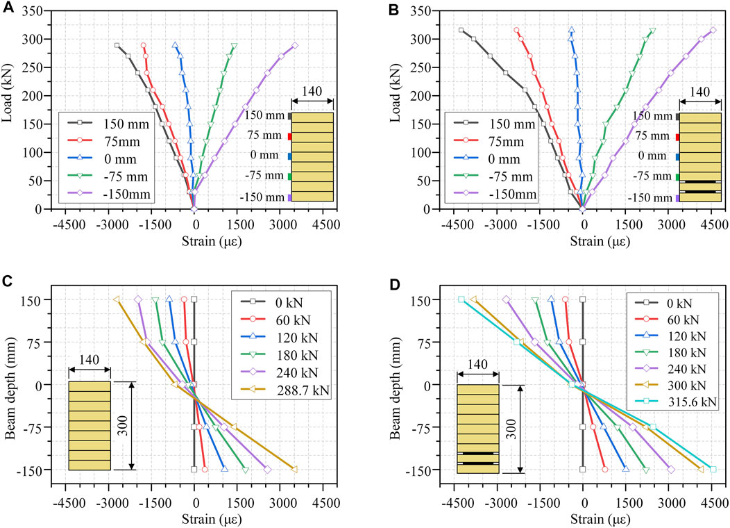
FIGURE 6. Strain distribution: load–strain curves of (A) group W and (B) group WH+H; and strain profile of (C) group W and (D) group WH+H.
TABLE 5. Experimental results of the strain profile.
As shown in Figure 6A, load–strain curves of the unreinforced specimen are almost linear, whereas as shown in Figure 6B, nonlinear behavior is illustrated for the load–strain curve from the uppermost fiber existing in the cross section (i.e., 150 mm) of the reinforced specimen. As listed in Table 5, when increasing the strengthening ratio from 0.4 to 0.8, the increasing ratio of the maximum compressive strain and that of the maximum tensile strain are enhanced from 25.93 to 57.20% and from 19.69 to 29.30%, respectively. It is also stated by Gentile et al. (2002) and Yang et al. (2016) that in FRP-reinforced glulam beams, the maximum tensile strain of wood fibers can be enhanced with an increase of the FRP strengthening ratio. It is noted that the maximum tensile strain of the tested beams is just 4,500 με, which indicates that the corresponding maximum tensile stress is much less than the tensile strength of the FRP sheet. It implies that the design of the reinforced beams was conservative, resulting into the little utilization of the CFRP strength. According to test results presented herein, an FRP sheet with a lower tensile strength is recommended for the FRP-reinforced glulam beams.
It should be noted that the negatively increasing ratio of −3.81% for the specimens in group WL might be caused by the glulam wrinkling that occurred during their bending tests, which increased the errors of the strain measured by the strain gauges mounted on the side surface of glulam beams. As shown in Figure 6C, the position of the neutral axis shows a downward trend in the cross section of the unreinforced specimen in group W, when the vertical load applied on the bending specimens increases. However, for the cross section of the CFRP-reinforced specimen in group WH+H, the position of its neutral axis almost remains stable, as shown in Figure 6D. The reason might be that for the unreinforced glulam specimen, the potential of further utilizing its compressive fibers is higher than that of utilizing the compressive fibers in CFRP-reinforced glulam beams.
A numerical analysis was conducted based on a commercial FEM program, ABAQUS (2020). The FEM models of all the six groups of specimens were developed to simulate the bending performance of both unreinforced and reinforced glulam beams. In these models, a solid part was created to represent the entire glulam beam. For the models of the reinforced specimens, an additional shell part was created to represent the CFRP sheets. The geometric dimensions of the FE models were identical to those of the specimens in the bending tests. In the model, no part was created for simulating the adhesive layer, whereas for considering the qualified bonding behavior between the glulam and the CFRP sheets, an “embedded region” was used to attach the part representing the CFRP to that representing the glulam, which is capable of coordinating the nodal displacements between two parts defined separately. Simple supports were defined on both ends of the bending specimens. The 8-node linear element type C3D8R and the 4-node doubly curved shell element type S4R were used for simulating the glulam and CFRP sheets, respectively.
For reducing the numerical calculation efforts, an isotropic material model featured by bilinear stress–strain relationship under compression and tension was assigned to the glulam, as shown in Figure 7. The material parameters in Figure 7 were defined based on the parallel-to-grain compressive tests on the small clear specimens, in which m was adopted as 0.1 based on the previous studies on the timber bending performance (Bazan, 1980; Buchanan, 1990; Gentile et al., 2002; Yang et al., 2016). Moreover, it should be noted that the adopted isotropic material properties of timber could also effectively avoid both the shear-bending failure and local perpendicular-to-grain compressive failure of timber, which is caused by the lower perpendicular-to-grain strength of timber and the smaller span-to-depth ratio of beam specimens. An isotropic material model featured by linear elasticity while without degradation section was assigned to the CFRP sheets, as shown in Figure 8. The input material parameters for the two types of CFRP sheets in the model were based on the mechanical properties listed in Table 2.
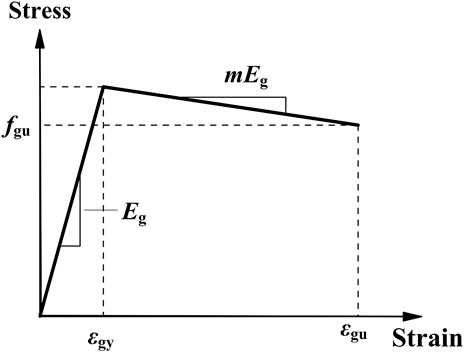
FIGURE 7. Stress–strain relationship of glulam in the FEM model.
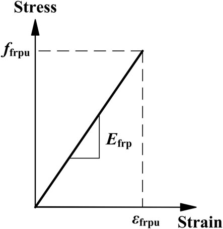
FIGURE 8. Stress–strain relationship of FRP in the FEM model.
The stress distribution of σ11 at a failure point for group WH+H is shown in Figure 9. As it can be seen in Figure 9A, the stress distribution of glulam belongs to a typical pure bending failure mode. As shown in Figure 9B, the maximum tensile stress (i.e., 1,638 MPa) of the CFRP sheet is much less than its tensile strength of 3,500 MPa, which is also observed in other reinforced models. It indicates that the tensile strength of the CFRP has the potential of being further utilized by adopting some other methods in the CFRP-reinforced glulam beams (e.g., the prestressing technology).
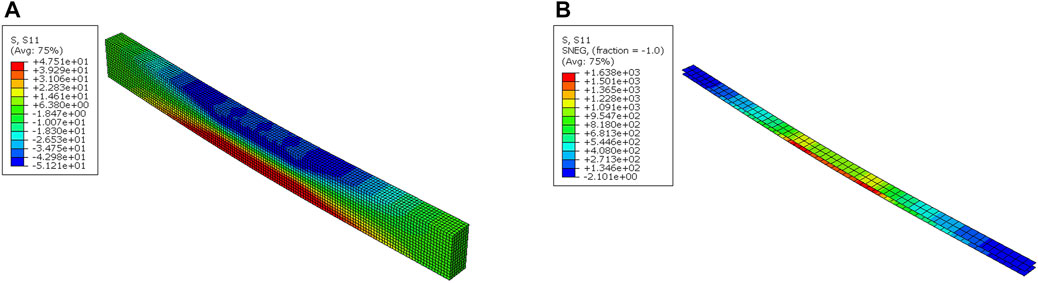
FIGURE 9. Stress distribution of σ11 in (A) glulam and (B) CFRP sheets for the FEM model of group WH+H.
Taking the groups of W and WH+H as examples, both their experimental and numerical load–deflection curves are plotted in Figure 10. As shown in Figure 10, the numerical curves fit well with the experimental ones, especially during the initial linear-elastic stage. Since the fracture of the bending glulam was not simulated in the model, the load from the numerical curves does not decline dramatically when the mid-span deflection increases beyond the point of the maximum load. Due to an immediate overall failure following the maximum load in beam specimens, modeling the decline section of load-deflection curves is meaningless for this research.
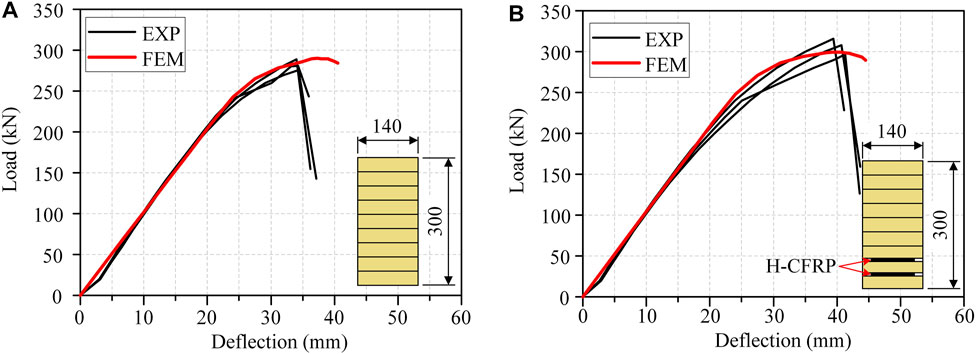
FIGURE 10. Comparison of load–deflection curves between the numerical results and the experimental results of (A) group W and (B) group WH+H.
A comparison was conducted between the numerical and experimental results including the maximum bending-resisting moment Mu and the apparent bending stiffness EappI, as listed in Table 6. For the Mu, ideal agreement can be achieved with a range of difference between 0.31 and 11.17%. For the unreinforced specimens, the Mu from the numerical model is higher than that from the experimental Mu due to the knots existing in unreinforced specimens, whereas such a trend does not exist for the reinforced specimens. For the EappI, the numerical values were calculated based on Eq. 1 from numerical curves, and a range of difference between 7.37 and 16.13% exists between the numerical EappI and the experimental EappI. For both the unreinforced and the reinforced specimens, the numerical EappI is lower than the experimental EappI. It indicates that the adopted MOE of the glulam in the FEM models is lower than the actual bending MOE of the glulam specimens.
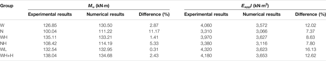
TABLE 6. Comparison of the numerical results to the experimental results.
A general analytical model was employed to theoretically predict the bending-resisting moment Mu,r and the bending stiffness Esf,rI of reinforced glulam beams, based on the following assumptions: 1) the strain profile remains linear during the whole loading process; 2) the longitudinal stress–strain relationship of the glulam follows the Bazan–Buchanan law (Bazan, 1980; Buchanan, 1990), where the compressive behavior is bilinear and the tensile behavior is linear as shown in Figure 11, in which m was adopted as 0.1 based on the tests on the glulam properties; and 3) the stress–strain relationship of CFRP sheets in tension is linear, as shown in Figure 8.
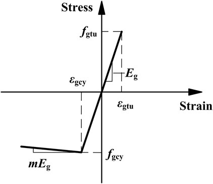
FIGURE 11. Stress–strain relationship for glulam in the theoretical model (Bazan, 1980; Buchanan, 1990).
The analytical model for predicting the bending-resisting moment of glulam beams reinforced with one layer of the CFRP sheet is illustrated in Figure 12. The bending failure occurs when the tensile stress of the glulam bottom fibers reaches their tensile strength fgtu. The tensile strength fgtu of the bottom fibers in the theoretical model was considered identical with the bending strength fm,r that was calculated based on Eq. 2, in which fm,un is the bending strength of unreinforced beams calculated based on their experimental bending-resisting moment Mu,un; α is the modification factor for considering the enhancement of the maximum tensile strain as the addition of CFRP reinforcement. The value of α was adopted as 1.2 herein, since for glulam beams reinforced with one CFRP sheet, the increasing ratio of their experimental maximum tensile strain was around 20%, as listed in Table 5. The depth of the neutral axis hgc can be calculated by introducing the mathematical relations and the values of variables into the internal force equilibrium condition in Eq. 3. Then the bending-resisting moment Mu,r can be calculated from Eq. 4.
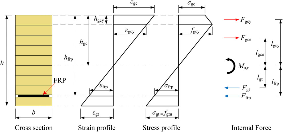
FIGURE 12. Theoretical model for predicting the Mu of the reinforced glulam beams.
The analytical model of glulam beams reinforced with two layers of the CFRP sheet is similar to that shown in Figure 12, except that totally two layers of CFRP sheets were positioned in the tensile area of their cross section. It should be noted that the value of α should be adopted as 1.3 herein, since the increasing ratio of the experimental maximum tensile strain was around 30% for glulam beams reinforced with two layers of CFRP sheets, as listed in Table 5.
For facilitating the follow-up comparison between the experimental and analytical properties, the experimental shear-free bending stiffness Esf,rI that could reflect the pure bending mechanism of reinforced glulam beams was induced from the experimental apparent bending stiffness Eapp,rI that actually reflected both the bending and shear mechanisms, based on Eq 5 from the ASTM D198-15 (2015). In Eq 5, λ is the factor calculated based on Eq. 6, which can exclude the influence from the existing shear deformation on the bending stiffness. The G12 in Eq. 6 was the shear modulus calculated from Eq. 7, where E1 and E2 are the MOE parallel-to-grain and perpendicular-to-grain, respectively; ν12 and ν21 are Poisson’s ratios according to the Wood handbook (Ross, 2010). Furthermore, the theoretical shear-free bending stiffness Esf,rI of reinforced glulam beams can be calculated by using the transformed section method. In this transformed section method, the adopted glulam MOE Eg is equal to the shear-free MOE Esf,un of unreinforced glulam beams, which can be calculated based on Eq. 8, in which the Eapp,unI is the experimental apparent bending stiffness of unreinforced glulam beams. The experimental results of both the Mu,r and the Esf,rI, and their predictive results from the analytical model are listed in Table 7.
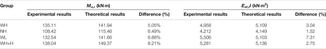
TABLE 7. Comparison of the theoretical results to the experimental results.
As listed in Table 7, ideal accuracy can be obtained between the experimental results and the predictive results with a difference of within 10%, in terms of both the bending-resisting moment Mu,r and the shear-free bending stiffness Esf,rI. It indicates that once the bending strength and the MOE of the glulam as well as the MOE of CFRP are determined, the bending performance of CFRP-reinforced glulam beams can be predicted accurately. It should be noted that the experimental Mu,r was slightly lower than the predicted Mu,r from the analytical model, which might be caused by the knots existing in the glulam bending specimens.
In this article, the bending performance of 18 glulam beams, unreinforced or reinforced with internally embedded CFRP sheets, was studied based on the four-point bending test; besides, both numerical analysis and theoretical analysis were also conducted. The conclusions can be drawn as follows:
1) All bending beams illustrate a brittle failure mode that resulted from the fracture of the bottommost lamination in the pure bending area. For unreinforced beams, the failure is mainly caused by the sudden brittle fracture of knots, whereas reinforced beams exhibited a slower failure process with observed crack propagating and wrinkling on the compressive side.
2) Since no slip failure occurred between the CFRP sheet and glulam in tests, PU adhesive is proven to be a suitable adhesive for the fabrication of CFRP-reinforced glulam beams.
3) Both the bending–resisting capacity and the maximum deflection of reinforced beams were enhanced with an increase of the CFRP strengthening ratio, and the bending performance can be enhanced more significantly when the CFRP sheets with a higher MOE were employed in glulam beams.
4) In reinforced beams, a nonlinear behavior was observed on the compressive side of beams, and the increasing ratio of the maximum compressive strain and tensile strain is up to 57.20 and 29.30%, respectively.
5) The numerical load–deflection curves of reinforced and unreinforced glulam beams agree well with the experimental curves; besides, a satisfactory difference within 10% exists between the experimental bending performance and the bending performance obtained from the general theoretical model.
The raw data supporting the conclusion of this article will be made available by the authors, without undue reservation.
MH contributed to conceptualization, methodology, investigation, and validation. YW contributed to data curation, formal analysis, software, and writing—original draft. ZL contributed to conceptualization, methodology, and investigation. LZ contributed to investigation and validation. YT contributed to methodology, investigation, and data curation. XS contributed to methodology, formal analysis, and writing—review and editing. All authors read and approved the final manuscript.
The authors gratefully acknowledge the support from the National Natural Science Foundation of China (Grant Nos. 52078371 & 52108242) and China Postdoctoral Science Foundation (Grant No. 2021M692444).
The authors declare that the research was conducted in the absence of any commercial or financial relationships that could be construed as a potential conflict of interest.
All claims expressed in this article are solely those of the authors and do not necessarily represent those of their affiliated organizations, or those of the publisher, the editors, and the reviewers. Any product that may be evaluated in this article, or claim that may be made by its manufacturer, is not guaranteed or endorsed by the publisher.
ASTM D143-14 (2014). Standard Test Methods for Small Clear Specimens of Timber. West Conshohocken, PA: ASTM international.
ASTM D198-15 (2015). Standard Test Methods of Static Tests of Lumber in Structural Sizes. West Conshohocken, PA: ASTM international.
Bazan, I. M. M. (1980). Ultimate Bending Strength of Timber beamsDissertation. Halifax, Nova Scotia, Canada: Nova Scotia Technical College.
Buchanan, A. H. (1990). Bending Strength of Lumber. J. Struct. Eng. 116116 (5), 1213–1229. doi:10.1061/(ASCE)0733-944510.1061/(asce)0733-9445(1990)116:5(1213)
Corradi, M., Borri, A., Righetti, L., and Speranzini, E. (2017). Uncertainty Analysis of FRP Reinforced Timber Beams. Composites B: Eng. 113, 174–184. doi:10.1016/j.compositesb.2017.01.030
Fiorelli, J., and Dias, A. A. (2011). Glulam Beams Reinforced with FRP Externally-Bonded: Theoretical and Experimental Evaluation. Mater. Struct. 44 (8), 1431–1440. doi:10.1617/s11527-011-9708-y
Fossetti, M., Minafò, G., and Papia, M. (2015). Flexural Behaviour of Glulam Timber Beams Reinforced with FRP Cords. Construction Building Mater. 95, 54–64. doi:10.1016/j.conbuildmat.2015.07.116
GB 50728-2011 (2011). Technical Code for Safety Appraisal of Engineering Structural Strengthening Materials. Beijing, China: China Standardization Administration.
GB/T 1933-2009 (2009). Method for Determination the Density of wood. Beijing, China: China Standardization Administration.
GB/T 15777-2017 (2017). Method for Determination of the Modulus of Elasticity in Compression Parallel to Grain of wood. Beijing, China: China Standardization Administration.
GB/T 1931-2009 (2009). Method for Determination the Moisture Content of wood. Beijing, China: China Standardization Administration.
Gentile, C., Svecova, D., and Rizkalla, S. H. (2002). Timber Beams Strengthened with GFRP Bars: Development and Applications. J. Compos. Constr. 6 (1), 11–20. doi:10.1061/(asce)1090-0268(2002)6:1(11)
Glišović, I., Pavlović, M., Stevanović, B., and Todorović, M. (2017). Numerical Analysis of Glulam Beams Reinforced with CFRP Plates. J. Civ. Eng. Manag. 23 (7), 868–879. doi:10.3846/13923730.2017.1341953
Gómez, E. P., González, M. N., Hosokawa, K., and Cobo, A. (2019). Experimental Study of the Flexural Behavior of Timber Beams Reinforced with Different Kinds of FRP and Metallic Fibers. Compos. Structures 213, 308–316. doi:10.1016/j.compstruct.2019.01.099
Johnsson, H., Blanksvärd, T., and Carolin, A. (2007). Glulam Members Strengthened by Carbon Fibre Reinforcement. Mater. Struct. 40 (1), 47–56. doi:10.1617/s11527-006-9119-7
Lindyberg, R. F., and Dagher, H. J. (2012). ReLAM: Nonlinear Probabilistic Model for the Analysis of Reinforced Glulam Beams in Bending. J. Struct. Eng. 138 (6), 777–788. doi:10.1061/(ASCE)ST.1943-541X.0000496
Lu, W., Ling, Z., Geng, Q., Liu, W., Yang, H., and Yue, K. (2015). Study on Flexural Behaviour of Glulam Beams Reinforced by Near Surface Mounted (NSM) CFRP Laminates. Construction Building Mater. 91, 23–31. doi:10.1016/j.conbuildmat.2015.04.050
Lv, Q., Ding, Y., and Liu, Y. (2019). Effect of the Nonprestressed/Prestressed BFRP Bar on Flexural Performance of the Bamboo Beam. Adv. Polym. Tech. 2019, 1–13. doi:10.1155/2019/7143023
McConnell, E., McPolin, D., and Taylor, S. (2014). Post-tensioning of Glulam Timber with Steel Tendons. Construction Building Mater. 73, 426–433. doi:10.1016/j.conbuildmat.2014.09.079
Nowak, T. P., Jasieńko, J., and Czepiżak, D. (2013). Experimental Tests and Numerical Analysis of Historic Bent Timber Elements Reinforced with CFRP Strips. Construction Building Mater. 40, 197–206. doi:10.1016/j.conbuildmat.2012.09.106
Plevris, N., and Triantafillou, T. C. (1992). FRP‐Reinforced Wood as Structural Material. J. Mater. Civ. Eng. 44 (3), 3003–3317. doi:10.1061/(ASCE)0899-156110.1061/(asce)0899-1561(1992)4:3(300)
Raftery, G. M., and Harte, A. M. (2013). Nonlinear Numerical Modelling of FRP Reinforced Glued Laminated Timber. Composites Part B: Eng. 52, 40–50. doi:10.1016/j.compositesb.2013.03.038
Raftery, G. M., and Whelan, C. (2014). Low-grade Glued Laminated Timber Beams Reinforced Using Improved Arrangements of Bonded-In GFRP Rods. Construction Building Mater. 52, 209–220. doi:10.1016/j.conbuildmat.2013.11.044
Rajczyk, M., and Jonczyk, D. (2019). Behavior of Glulam Beams Strengthened with BFRP Bars. IOP Conf. Ser. Mater. Sci. Eng. 603, 042004. doi:10.1088/1757-899x/603/4/042004
Ross, R. J. (2010). Wood Handbook: wood as an Engineering Material. American: USDA Forest Service, Forest Products Laboratory.
Sun, X., He, M., and Li, Z. (2020). Novel Engineered wood and Bamboo Composites for Structural Applications: State-Of-Art of Manufacturing Technology and Mechanical Performance Evaluation. Construction Building Mater. 249, 118751. doi:10.1016/j.conbuildmat.2020.118751
Vahedian, A., Shrestha, R., and Crews, K. (2019). Experimental and Analytical Investigation on CFRP Strengthened Glulam Laminated Timber Beams: Full-Scale Experiments. Composites Part B: Eng. 164, 377–389. doi:10.1016/j.compositesb.2018.12.007
Wei, Y., Yan, S., Zhao, K., Dong, F., and Li, G. (2020). Experimental and Theoretical Investigation of Steel-Reinforced Bamboo Scrimber Beams. Eng. Structures 223, 111179. doi:10.1016/j.engstruct.2020.111179
Yang, H., Liu, W., Lu, W., Zhu, S., and Geng, Q. (2016). Flexural Behavior of FRP and Steel Reinforced Glulam Beams: Experimental and Theoretical Evaluation. Construction Building Mater. 106, 550–563. doi:10.1016/j.conbuildmat.2015.12.135
Keywords: glulam beam, CFRP sheet, four-point bending test, numerical model, theoretical analysis
Citation: He M, Wang Y, Li Z, Zhou L, Tong Y and Sun X (2022) An Experimental and Analytical Study on the Bending Performance of CFRP-Reinforced Glulam Beams. Front. Mater. 8:802249. doi: 10.3389/fmats.2021.802249
Received: 26 October 2021; Accepted: 13 December 2021;
Published: 10 January 2022.
Edited by:
Lik-ho Tam, Beihang University, ChinaCopyright © 2022 He, Wang, Li, Zhou, Tong and Sun. This is an open-access article distributed under the terms of the Creative Commons Attribution License (CC BY). The use, distribution or reproduction in other forums is permitted, provided the original author(s) and the copyright owner(s) are credited and that the original publication in this journal is cited, in accordance with accepted academic practice. No use, distribution or reproduction is permitted which does not comply with these terms.
*Correspondence: Xiaofeng Sun, MjEzMTAwMDZAdG9uZ2ppLmVkdS5jbg==
Disclaimer: All claims expressed in this article are solely those of the authors and do not necessarily represent those of their affiliated organizations, or those of the publisher, the editors and the reviewers. Any product that may be evaluated in this article or claim that may be made by its manufacturer is not guaranteed or endorsed by the publisher.
Research integrity at Frontiers
Learn more about the work of our research integrity team to safeguard the quality of each article we publish.