- 1Senior Lecturer, The Department of Civil Engineering, Universiti Malaysia Sarawak, Kota Samarahan, Malaysia
- 2Graduate Student, The Department of Civil Engineering, Universiti Malaysia Sarawak, Kota Samarahan, Malaysia
In-stope paste backfill monitoring at different mine sites showed anomalous increase in total stress during rest periods. One of the explanations according to a recent laboratory- model experiment was attributed to volumetric expansion caused by temperature increase within the backfill. This paper extends the understanding whether the Mohr–Coulomb’s effective strength parameters are affected by such temperature increase. The effects are explained through evaluating the apparent cohesion and the effective internal and interfacial friction angles under different temperature conditions. A series of modified direct shear tests were performed on saturated specimens under three controlled temperature levels: 25°C, 50°C, and 70°C. The specimens consist of cemented paste backfill and uncemented paste backfill. The results show that the effective internal and the interfacial friction angles increase as the temperature increases, depending on the type of material and the shearing condition, whereas the temperature increase does not significantly affect the apparent cohesion. The findings serve as a reference for engineers and academics in explaining the stress anomaly and to better understand the shear behavior of paste backfill under different temperature conditions for mine stope backfill design.
Introduction
Technological advancement increases the demand on the minerals which could be fulfilled through mining (Yilmaz et al., 2003; Bai et al., 2018). The scarcity of minerals in the shallow ground level necessitates deeper underground level to be explored by the industry to stay profitable (Sheshpari 2015). Underground mining produces mined-out voids (stopes) that could cause underground instability and indirectly give impact to the ore recovery rate and safety issues (Rankine and Sivakugan 2007; Xuan et al., 2013; Adajar and Pabilona 2018). Concurrently, mining processing plants also generate a significant amount of waste rock and tailings.
Paste backfilling is a relatively new tailings management technique, which utilizes tailing in the form of a paste as the backfill material, also known as paste backfill, to fill-up stopes and improve general underground stability. Paste backfill stabilized with cement binder is commonly known as cemented paste backfill (CPB). The CPB has been used in many underground mining operations due to its technical, environmental, and economic strong points (Li and Yang 2015; Jaouhar et al., 2018). The CPB is a flowable material that is made from dewatered tailing, cement binder, and water. It can become a self-supporting material after a few days to provide adjacent support within stopes (Helinski et al., 2007; Ghirian and Fall 2015). The widely used mix proportion of CPB uses cement binder approximately 3%–7% by dry weight and tailings approximately 70%–85% by total weight (Landriault 1995; Orejarena and Fall 2011). The CPB with 2.5%–7% water to cement ratio has better flowability without clogging the pipeline (Ramlochan et al., 2004).
After gaining enough shear strength, the weight of the backfill is transferred to the stope bottom and sidewalls due to a phenomenon, known as arching (Fahey et al., 2009). When arching occurs in a filled stope, the vertical stress at the bottom of the fill is less than the fill’s weight due to stress transfer to the stope sidewalls (Janssen 1895; Marston 1930; Terzaghi 1943). Arching is primarily associated with the frictional and/or cohesive interaction between the backfill and the stope sidewalls (Belem and Benzaazoua 2008; Moradi and Abbasnejad 2015).
The stability of CPB structures is a function of many factors, such as the mechanical properties of the CPB as well as the interfacial properties between the CPB and the sidewalls. Therefore, the understanding on the interfacial shear strength parameter of the CPB stope sidewall is important (Nasir and Fall 2008; Koupouli et al., 2016). In common design practice, the interfacial friction angle of CPB is often ignored as the shear failure is not likely to occur at CPB rock interface due to the high surface roughness of the unevenly blasted wall (Pierce 2001).
In-stope monitoring of CPB deposition at different mine sites shows an anomalous stress increase during rest periods, which was speculated due to the increase in temperature (Thompson et al., 2012; Hasan et al., 2014; Doherty et al., 2015). The rest period in this paper refers to the period after the backfilling stops either temporarily (i.e., between plug pour and subsequent backfilling) or permanently (i.e., after the final backfilling). The presence of additional heat causes the CPB to expand and, therefore, increases the exerted pressure (Mitchell et al., 1982). The available in situ data show that the temperature typically increases up to 50°C (Grabinsky and Thompson 2009; Thompson et al., 2012; Hasan et al., 2014). The change in shearing temperature constitutes to the final shear parameter of the material (Karademir 2011). Lee et al. (2016) showed the significance of the shear parameter on the reduction of earth pressure in stress transfer. As a consequence of the temperature increase, the strength parameter obtained from tests at a constant temperature may not be adequate to explain the stress distribution within the backfill.
A recent laboratory model experiment has shown that the temperature increase within the backfill can potentially cause an increase in total stress (Hasan et al., 2018; Ting et al., 2020). The paste backfill expands as shown by the volumetric strain observed from the unrestrained top of the backfill during the temperature increase. Such evident has proved that the temperature increase directly affects the total stress parameter of the paste backfill through the volumetric expansion. On the other hand, an alternative explanation for total stress increase was associated with creep behavior of the surrounding rock mass, which was proven through numerical investigation and a few backfill tests (Qi and Fourie 2019). These two explanations are independent in nature; therefore, the anomaly might be caused by either one or both at the same time.
Figure 1 illustrates the importance of the paste backfill mechanism within stope wall when there is a thermal expansion due to the temperature increase. As the backfill is deposited within a stope, the vertical stress is transferred to the sidewalls due to arching; exothermic reaction from the cement hydration and other sources of heat contribute to the expansion. Thus, arching is intensified. To date, there have been no explanations on how this temperature increase affects the Mohr–Coulomb’s effective strength parameters of the paste backfill.
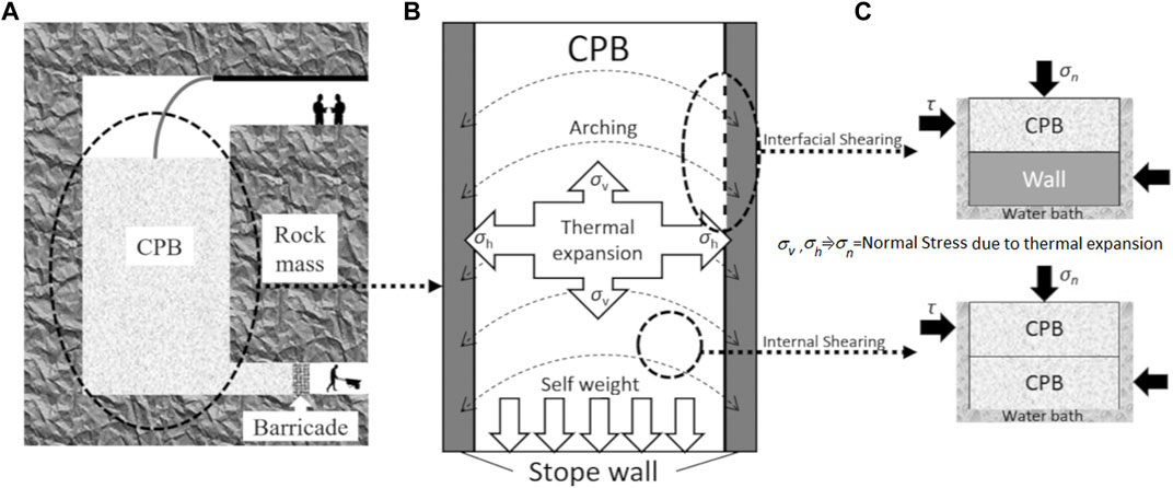
FIGURE 1. Illustration of paste backfill mechanism. (A) Deposition of CPB into stope, (B) stress mechanism of CPB, and (C) simulated mechanism in laboratory test.
Mohr–Coulomb’s effective strength parameters are expressed a linear relationship between the shear stress, τ, kPa (y-axis), and normal effective stress, σ’, kPa (y-axis) as follows:
where c’ is the intercept of the linear model (equation) to y-axis and the ϕ′ is the effective friction angle. The c’ is appropriately known as apparent cohesion, in which the value can be originated from the true cohesion (in cohesive or cemented materials) or merely as a result of statistical curve fitting. Experimental evidences showed that Mohr–Coulomb linear relationship can produce a statistical apparent cohesion in cohesionless granular material, which is contributed from the dilatancy, particle angularity, and interlocking (Alshibli et al., 2000).
The objective of this paper is to extend the understanding whether the Mohr–Coulomb’s effective strength parameters are affected by the temperature increase by presenting the experimental results on the paste backfill in the forms of the apparent cohesion and the internal and interfacial friction behaviors under different shearing temperature conditions. The results were obtained from a series of modified direct shear tests, which will improve the understanding regarding the stress parameters within the backfill when the increase in temperature is expected.
Materials and Methods
The CPB is reproduced in the laboratory by mixing fine silica flour, binder, and water. The properties of these three materials are determined and controlled to ensure the reproducibility and repeatability of the results. For comparison purposes, the uncemented paste backfill (UCPB) is also investigated along with the CPB.
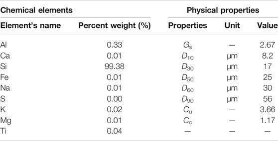
Silica flour is selected as tailing replacement material. It is a finely ground crystalline silica manufactured by SILVERBOND® Pasir Gudang, Johor, Malaysia. It contains high purity of SiO2 quartz and free of sulfide minerals as shown in Table 1. Note that the presence of sulfide is undesirable because sulfide oxidizes into sulfate and affects the shear strength of CPB. The silica flour is inert, is neutral in pH, comes with good uniformity, and shall not degrade at high temperature (<110°C).
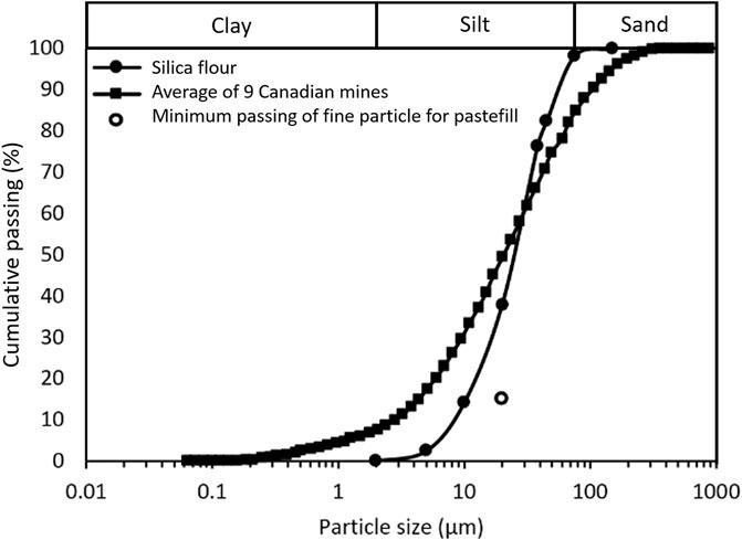
The use of silica flour as tailing replacement has been widely adopted by researchers (Fall et al., 2010; Wu et al., 2016) due to its similarity of particle size toward the average of nine Canadian mine tailings (Nasir and Fall 2008; Fall et al., 2010; Abdul-Hussain and Fall, 2012; Ghirian and Fall, 2015). Its mixture with water can be categorized as paste fill because it contains particles at least 15% cumulative passing of 20 μm (Potvin et al., 2005). Figure 2 shows the particle size distribution of the silica flour. The particle’s mean diameter, d, is 25 μm, and the coefficient of uniformity, Cu, is 3.66. The physical properties of the silica flour are summarized in Table 1.
Ordinary Portland cement (OPC) is used as the binder for CPB. It is obtained from a local company cement producer Cahya Mata Sarawak (CMS), whose quality of cement conforms with the standard requirement specified in Malaysian Standard MS EN 94 197-1, which is equivalent to ASTM C150.
Tap water is used for mixing, which is neutral in pH, free from chemical residual, low total dissolved solids, and no salinity as stated in the quality control standards. The water pH, the total dissolved solids, and the salinity are 6.84, 74.3 ppm, and 0.0627 ppt, respectively. These data are obtained from water quality tests using PCSTestr35 EUTECH Instruments.
Modified Direct Shear Tests
Apparatus
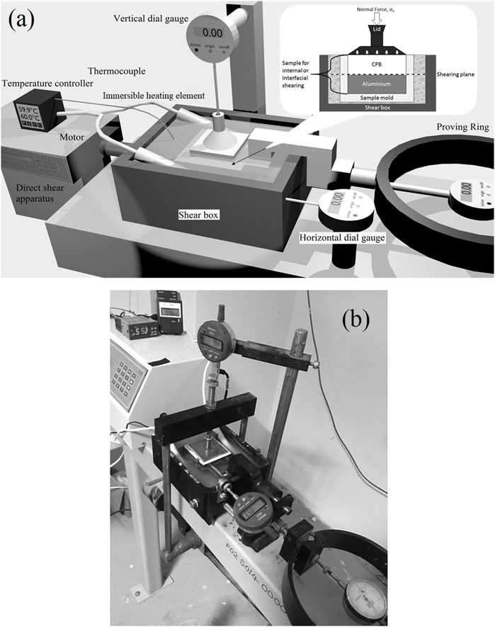
ELE International digital direct shear apparatus is used as the main component. A temperature controlling system is incorporated in the direct shear apparatus, which consists of a digital temperature controller, two heating elements, and a thermocouple. For the interfacial shear test, the mold is modified such that only the upper half (top) is filled with paste sample whereas the lower half (bottom) is replaced with an aluminum plate to simulate the stope sidewalls. The aluminum plate measures 60 mm wide, 60 mm long, and 5 mm thick. Note that it has the same cross-sectional area as the inner side of the mold. The sample and the aluminum surface were precisely positioned at the shearing plane. Aluminum material is used because it has an elastic modulus of about 70 GPa, which is in the range of the elastic modulus of the rock mass (20–100 GPa) in mine stopes (Hoek and Diederichs 2006; Belem and Benzaazoua 2008). For every test, a new aluminum plate obtained from the same material is used to ensure similar surface roughness.
The direct shear test is performed conforming to ASTM (2011). During the test, the shear box is filled with water to keep the sample fully saturated throughout shearing. Water heating elements are immersed in the shear box to generate heat. The temperature is controlled and monitored using a temperature controller and thermocouples. Such incorporation of temperature controlling system as shown in Figure 3A does not cause disturbance toward the shearing process. Normal stress is applied accordingly, and the sample is sheared under drained condition at the rate of 1 mm/min until 15% shear strain is achieved. The shearing rate is selected on the basis of the longest time required for UCPB or CPB samples to achieve 90% consolidation (t90), which is measured at about 0.5 min (ASTM, 2011). The total elapsed time to failure is 5.8 min, and the horizontal displacement at failure is about 6 mm. Thus, the maximum displacement rate suitable for these experiments is 1.0 mm/min. During testing, the pore water is freely to dissipate (drain-out) from the top and bottom of the mold. A photograph of the setup is shown in Figure 3B.
Sample Preparation and Tests
Fresh silica flour that consists of less than 0.2% bulk water content (from the bag) is used for the preparation of all samples. A series of slump tests and UCS tests are performed to acquire the most suitable mix design for both UCPB and CPB, which are illustrated in Figure 4. Unconfined compressive strength (UCS) of CPB is usually between 200 and 5,000 kPa, but the common target strength in practice is 1,000 kPa at 28 days or 300 kPa at 3 days (Sheshpari 2015). Ghirian and Fall (2016) and Wu et al. (2016) also showed similar findings, where at 3 days of curing, the UCS should be approximately 300 kPa. From Figure 4A, 5% of the binder is chosen to obtain the UCS at approximately 300 kPa after 3 days of curing. The amount of OPC (binder) used is decided by the percentage of solid dry mass, Bw, as given in Eq. 1.
where WB is the weight of binder and Wdry-S is the dry weight of solid.
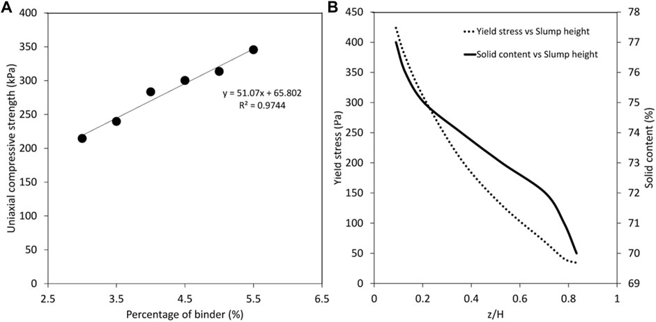
FIGURE 4. Slump and strength tests results. (A) UCS versus percent binder. (B) Yield stress versus solid content and normalized slump height for samples with 5% cement binder content.
Figure 4B shows the relationship between three variables, solid content, yield stress, and normalized slump height (z/H) for samples with 5% cement binder content. Note that z is the slump and H is the height of the slump cylinder. A range of normalized slump height (z/H) versus yield stress estimation is also shown in Figure 4B, which is adopted from Pashias et al. (1996). Yield stress below 200 Pa is recommended for a clog-free flow within the pipeline (Cooke 2008). Therefore, 72% solid content with 115 Pa of yield stress is chosen.
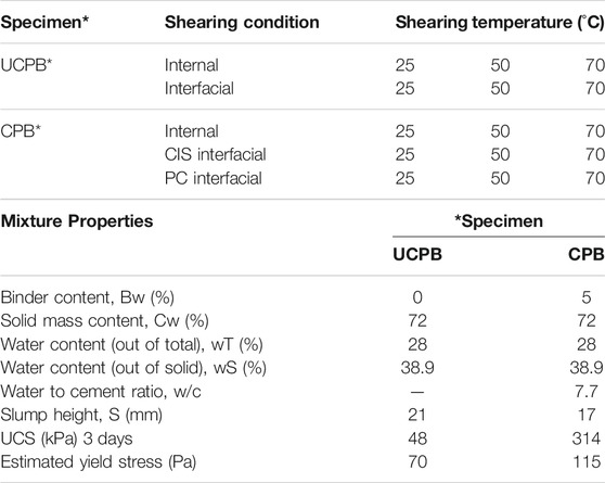
Table 2 lists the number of specimens and tests conducted. Mix composition of 72% solid content and 28% water content are used for UCPB and CPB sample specimens. The cement binder content for UCPB and CPB are 0% and 5%, respectively, for all tests. The water–cement ratio for CPB is 7.7. UCPB and CPB specimen’s mixture properties are summarized in Table 2. Three levels of temperature are selected, 25°C, 50°C, and 70°C. The lowest temperature represents the normal ambient temperature when paste is poured into the stope. The middle temperature represents the typical temperature increase based on available literature data, whereas the highest temperature is chosen to look at further effect at the higher temperature level. Two types of shearing conditions are applied to UCPB and CPB specimens, namely, internal (INT) and interfacial (IFC) tests. The interfacial tests for CPB are further divided into two types, namely, precast (PC) and cast in situ (CIS). Unlike CIS, the PC specimen is prepared in an external mold prior to testing, which does not possess the cementation bonding between CPB and its shearing surface. The paste is mixed with water in a flour mixer until it becomes homogenous. The time of mixing is approximately 5 min, which is within dissolution stage of hydration process. The PC specimen is prepared by pouring the mix into a 60 mm–by–60 mm mold (the same size as the direct shear mold), whereas CIS CPB specimen is casted directly in the direct shear box mold. Figure 5 shows specimens before testing. The CPB specimen is cured under high humidity for 2 days and cured under saturated condition for the remaining 1 day. The binder content and curing time are maintained for every test as the internal and interfacial shear behavior is significantly affected but does not apply to CPB specimens that are prepared using PC.
Results and Discussions
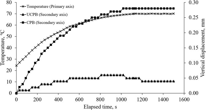
The expansion of UCPB and CPB specimens is evident from the vertical displacement from dial gauge measurement as shown in Figure 6. As the temperature increases, both types of specimen expand vertically until the temperature becomes constant. The CPB specimen maintains its vertical displacement, whereas the UCPB specimen shows a slight decrease after the peak is reached. It is thought due to that particles in UCPB specimens can freely rearrange and reconsolidate during the temperature increase, whereas the cementation in CPB prevents such rearrangement. As a result, the vertical displacement between CPB and UCPB appears to be quite significant. It is also shown in Figure 6 that the time to reach a constant temperature is approximately 1,100 s. For the estimation based on simple calculation using thermal conductivity formula, the time needed to heat the specimen from 24°C to 70°C is only about 88.6 s. The time difference between actual and calculated might be due to the heat dissipation to the box mold, box carriage, and the surrounding air.
The stress–strain curves for UCPB and CPB are shown in Figure 7 and Figure 8, respectively. In general, the stress increases as the strain increases until peak stress is reached after which the stress becomes constant. Peak stresses are mostly shown for CPB samples, where the stress slightly diminishes afterward and becomes constant at residual.
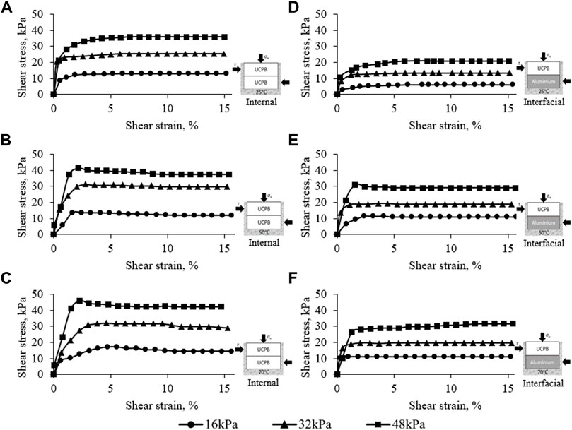
FIGURE 7. Shear stress–strain of UCPB under different shearing conditions. (A) INT UCPB at 25°C, (B) INT UCPB at 50°C, (C) INT UCPB at 70°C, (D) IFC UCPB at °C, (E) IFC UCPB at 50°C, and (F) IFC UCPB at 70°C.
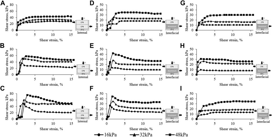
FIGURE 8. Shear stress–strain of CPB under different shearing conditions. (A) INT CPB at 25°C, (B) INT CPB at 50°C, (C) INT CPB at 70°C, (D) CIS IFC CPB at 25°C, (E) CIS IFC CPB at 50°C, (F) CIS IFC CPB at 70°C, (G) PC IFC CPB at 25°C, (H) PC IFC CPB at 50°C, and (I) PC IFC.
Internal and Interfacial Shear Stress of UCPB at Different Temperature
Figures 7A–C show the stress–strain behavior of the INT UCPB, whereas Figures 7D–F show the interfacial stress–strain behavior between UCPB and aluminum plate (IFC UCPB) at different temperature conditions. The initial density of the UCPB samples is 1,750 kg/m3. On average, the peak stress of IFC UCPB is lower than peak stress of INT UCPB by an average of 32.25%.
Upon reaching the desired temperature, non-cohesive material such as UCPB is able to reconsolidate to balance out the change in volume caused by thermal expansion. After reconsolidation, the material behaves slightly over-consolidated. Therefore, small differences in peak residual strength are observed at 50°C and 70°C.
Overall, Figure 7 shows that the shear stress for internal shearing is higher than stress for interfacial shearing. This is expected because the shear plane for interfacial shearing takes place between paste-and-smooth aluminum plate as compared to particle-and-particle in internal shearing. For INT UCPB, there is a total gain of stress by 16.36% from 25°C to 50°C and by 10.40% from 50°C to 70°C that is with an average gain of 0.156 kPa/°C. As for the interfacial shearing, there is a total gain of stress by 18.52% from 25°C to 50°C and by 11.38% from 50°C to 70°C that is with an average gain of 0.098 kPa/°C.
Internal and Interfacial Shear Stress of CPB at Different Temperature
Figures 8A–C show the shear stress–strain behavior of INT CPB at different temperature conditions, whereas Figures 8D–I show the interfacial shear stress strain behavior of CPB and aluminum plate (IFC CPB) using different casting methods, namely, CIS (8d to 8f) and PC (8g–8i) specimen’s preparation. The peak stress is observed at the region less than 3% shear strain for both internal and interfacial shearing. It is observed during this experiment that there is a cement bonding seen in between CIS CPB and the surface of the aluminum. The interfacial shear stress of CIS IFC CPB is lower than the shear stress INT CPB by an average of 36.26%. During post-interfacial shear test, the sample is inspected and found that every sample had nearly perfect failure occurring precisely on the shearing plane although some small irregularities are observed.
After the peak stress is reached, the stress remains or reduces to the residual state after 3% shear strain. INT CPB possesses the highest shear strength, then followed by CIS IFC CPB, and finally PC IFC CPB as the weakest. For INT CPB, there is a total gain of stress by 36.96% from 25°C to 50°C and by 27.26% from 50°C to 70°C that is with an average gain of 0.583 kPa/°C. As for IFC CPB, there is a total gain of stress by 17.38% from 25°C to 50°C and by 11.40% from 50°C to 70°C that is with an average gain of 0.176 kPa/°C. Figures 8G–I (CIS CPB) show similar stress–strain behavior as Figures 8D–F (PC CPB). They show that CIS CPB possesses higher shear stress by an average of 12.46%.
Apparent Cohesion and Friction Angle Comparison at Different Temperature Conditions
Overall, CPB specimens possess higher shear stress than UCPB samples at higher temperatures. The difference is clearly contributed from the cohesivity of the CPB due to cement bonding that gives additional strength to the shearing. INT CPB shows stress with an average of 85.95% higher than INT UCPB, whereas the same increment applies for IFC CPB by an average of 69.25% in comparison to IFC UCPB. The effect of temperature on INT CPB and CIS IFC CPB tests shows higher shear strength increment, whereas it only shows slight inconsistent increment on INT UCPB, IFC UCPB, and PC IFC CPB tests. The peak residual stress is more significant for CPB in comparison to UCPB.
Figure 9 shows the Mohr–Coulomb envelope of UCPB and CPB under different shearing conditions, and Table 3 lists values of the apparent cohesion and friction angle obtained from Figure 9. These envelopes are produced by fitting a linear regression line for each dataset. Every shear failure envelope obeys the Mohr–Coulomb failure criterion where the increase in stress is linear to the normal stress induced. Figure 10 shows the Mohr–Coulomb effective strength parameters at different temperature conditions.
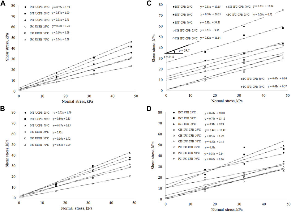
FIGURE 9. Mohr–Coulomb envelope on (A) peak stress of UCPB, (B) residual stress of UCPB, (C) peak stress of CPB, and (D) residual stress of CPB under different shearing conditions.
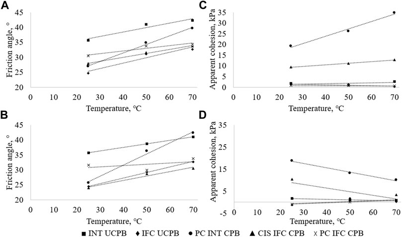
FIGURE 10. Effects of temperature on (A) peak friction angle, (B) residual friction angle, (C) peak apparent cohesion and (D) residual apparent cohesion for every sample.
It is expected that the apparent cohesion is negligible (or zero) for cases other than INT CPB and CIS IFC CPB. Minor apparent cohesion in the range of 0.1–2.7 kPa is obtained as results from curve fitting. It is noticeable from the UCPB Mohr–Coulomb envelope that the minor apparent cohesion created in INT UCPB shearing, in general, is higher than IFC UCPB. PC CPB at 3 days found to be slightly dissolved by the water during saturation. The dislodgement of CPB particles causes the surface of CPB to be slightly adhesive when the specimen was removed from water. However, because the rate of the displacement was low enough, the small value of apparent cohesion (i.e., less than 1 kPa) in PC UCPB might also be originated from curve fitting. The apparent cohesion obtained from INT CPB shearing is greater than CIS IFC CPB by 104.6% at 25°C, 135.7% at 50°C, and 171.1% at 70°C. Figure 10C shows that higher temperature has a positive effect on the peak apparent cohesion value of the CIS IFC CPB sample and a greater influence on the INT CPB sample. However, Figure 10D shows that the residual apparent cohesion for CIS IFC CPB decreases as the temperature increases. This could be due to the effect of difference in thermal expansion between the plate and CPB on compromising hydration bond, which is reflected in residual apparent cohesion. For INT CPB, there is a total gain of apparent cohesion by 37.06% from 25°C to 50°C and by 32.61% from 50°C to 70°C that is with an average gain of 0.356 kPa/°C. As for IFC CPB, there is a total gain of stress by 18.99% from 25°C to 50°C and by 15.29% from 50°C to 70°C that is with an average gain of 0.078 kPa/°C.
The friction angle generally increases with respect to the increase of shearing temperature, but the increment of friction angle varies according to the material and shearing condition. Unlike apparent cohesion values, the angle of friction of PC IFC CPB is found to be higher than that of CIS IFC CPB for both peak and residual, which means that interfacial area in PC IFC is rougher than CIS IFC. The interfacial roughness condition from two materials (CPB and plate) just introduced before the test contributes to a higher interfacial friction angle compared to the interface created in CIS IFC (although previously bonded). The friction angles in IFC UCPB are slightly closer to the CIS IFC CPB compared to PC IFC CPB. The effect of adhesion bonding during CIS only increases the apparent cohesion but not the friction angle. The friction angle of IFC UCPB is significantly lower by an average of 25.64% due to the smooth surface of aluminum platforms in comparison to friction angle of INT CPB. The friction angle of PC IFC CPB is higher than that of IFC UCPB by an average of 11.38% as the surface roughness of CPB aluminum is higher than that of UCPB aluminum.
Although INT CPB acquires the greatest gain in friction angle at higher temperatures (0.23°/°C), UCPB or non-coesive sample generally possesses a greater friction angle although the gain (0.07–0.14°/°C) due to temperature is less significant as shown in Figure 10. Cohesive material (i.e., INT CPB and CIS IFC CPB) possesses lower frictional angle because of the higher initial stress needed to overcome cementation bond. Thus, it shows less stress gain from the variation of normal stress applied and reduces the friction angle of the material upon obeying the linear law of Mohr–Coulomb envelope. On the basis of Figure 11, the effects of change in temperature on the change of friction angle and apparent cohesion can be clearly seen.
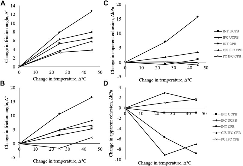
FIGURE 11. Effect of change in temperature on the change of (A) peak friction angle, (B) residual friction angle, (C) peak apparent cohesion, and (D) residual apparent cohesion for every sample.
Some of the findings on thermal shearing using different materials, shearing plane, and temperature range are used to be compared with the findings from this study (Figure 12). Different types of sand and clay had been used to investigate the effect of temperature on its shear behavior, but none had performed such testing on CPB. The clay is slightly affected by the change in temperature, but the effect on the changes in friction angle is inconsistent as reported by Hueckel and Baldi (1990), Burghignoli et al. (2000), and Cekerevac (2003). The effect of temperature on interfacial shearing is discussed by Karademir (2011) by varying the surface plane with high-density polyethylene and polyvinyl chloride with Blast sand and Ottawa sand. The finding shows a clear increment of friction angle with the increase in shearing temperature for every variation. Such findings discussed above are comparable to INT UCPB and IFC UCPB. The interfacial friction angle at the backfill aluminum is lower than internal friction angle of the backfill itself with an average factor of 0.69 at room temperature in comparison to 0.67, which is commonly used.
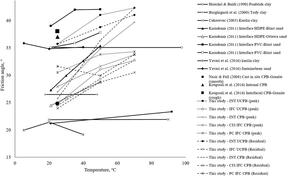
FIGURE 12. Summary of findings from stated researchers on different material, shearing plane, and temperature.
Nasir and Fall (2008) showed the interfacial friction angle and adhesion of CIS CPB to be 24.78° and 27.06 kPa, respectively, with no shearing temperature stated, and smooth limestone rock was used (dry, binder = 4.5%, w/c = 7.6, and cured at 3 days). The adhesion is higher than our results as the surface roughness of aluminum is smoother than the rock that is claimed to be smooth. Koupouli et al. (2016) showed that the internal and interfacial friction angle along with adhesion of CPB and in between PC CPB and smooth granite 266 rock were 37° and 15 kPa and 38° and 8 kPa, respectively (shearing temperature not stated), that is 102.7% higher for friction angle and 46.7% lower for apparent cohesion.
Conclusion
The paper presents the experimental results on the shear strength behavior of effective internal and interfacial friction between UCPB and CPB with 5% binder content, observed at the temperature of 25°C, 50°C to 70°C under five different shearing conditions and three effective stress levels (16, 32, and 48 kPa). Comparisons between the findings with related published data are reported. A thorough analysis is made on each dataset obtained; then, the following conclusions can be drawn:
• The shear failure envelopes both internal and interfacial tests at all temperature fit Mohr–Coulomb failure criterion.
• The effective internal and interfacial friction angle (ϕ℈) values increase with temperature.
• The temperature does not significantly affect the apparent cohesion.
• The interfacial shear parameters for both CIS and PC IFC CPB aluminum are comparable with the previous finding on interfacial shear behavior of CIS and PC CPB rock (assumed to be at room temperature of 25°C).
This study shows the significance of accurate design parameters such as shear strength, apparent cohesion, and friction angle at different temperature conditions for realistic and safer stress distribution estimation on mine backfill design.
Data Availability Statement
The raw data supporting the conclusion of this article will be made available by the authors, without undue reservation.
Author Contributions
AH is the lead investigator. WT is the student of the lead investigator who conducts the experiment under the guidance of the lead investigator.
Funding
This research is financially supported by Fundamental Research Grant Scheme (no. FRGS/TK01 (01)/1301/2015 (18)) by the Ministry of Higher Education Malaysia.
Conflict of Interest
The authors declare that the research was conducted in the absence of any commercial or financial relationships that could be construed as a potential conflict of interest.
Publisher’s Note
All claims expressed in this article are solely those of the authors and do not necessarily represent those of their affiliated organizations or those of the publisher, the editors, and the reviewers. Any product that may be evaluated in this article, or claim that may be made by its manufacturer, is not guaranteed or endorsed by the publisher.
Acknowledgments
The authors would also like to acknowledge the technical support and facilities provided by the Department of Civil Engineering, University of Malaysia Sarawak.
References
Abdul-Hussain, N., and Fall, M. (2012). Thermo-hydro-mechanical Behaviour of Sodium Silicate-Cemented Paste Tailings in Column Experiments. Tunnelling Underground Space Tech. 29, 85–93. doi:10.1016/j.tust.2012.01.004
Adajar, M. Q., and Pabilona, W. K. (2018). Soil-structure Interface Behavior of Cemented-Paste Backfill Material Mixed with Mining Waste. Int. J. GEOMATE 14 (44), 102–108. doi:10.21660/2018.44.7109
Alshibli, K. A., Sture, S., and Costes, N. C. (2000). Constitutive and Stability Behavior of Soils in Microgravity Environment. AIP Conf. Proc. 504, 246–252. doi:10.1063/1.1302489
ASTM (2011). D3080 Standard Test Method for Direct Shear Test of Soils under Consolidated Drained Conditions. West Conshohocken. PA: ASTM International.
Bai, E., Guo, W., Tan, Y., and Yang, D. (2018). The Analysis and Application of Granular Backfill Material to Reduce Surface Subsidence in China's Northwest Coal Mining Area. PLoS ONE 13 (7), e0201112. doi:10.1371/journal.pone.0201112
Belem, T., and Benzaazoua, M. (2008). Design and Application of Underground Mine Paste Backfill Technology. Geotech Geol. Eng. 26 (2), 147–174. doi:10.1007/s10706-007-9154-3
Burghignoli, A., Desideri, A., and Miliziano, S. (2000). A Laboratory Study on the Thermomechanical Behaviour of Clayey Soils. Can. Geotech. J. 37 (4), 764–780. doi:10.1139/t00-010
Cekerevac, C. (2003). Thermal Effects on the Mechanical Behaviour of Saturated Clays: an Experimental and Constitutive Study. Ph.D Dissertation. Lausanne(Switzerland): EPFL.
Cooke, R. (2008). “Pipeline Design for Paste and Thickened Tailings Systems,” in Proceedings of the 12th International Conference of Tailings and Mine Waste '08, Vail, Colorado, USA, October 19-22, 2008, 95–100. doi:10.1201/9780203882306.ch9
Doherty, J. P., Hasan, A., Suazo, G. H., and Fourie, A. (2015). Investigation of Some Controllable Factors that Impact the Stress State in Cemented Paste Backfill. Can. Geotech. J. 52 (12), 1901–1912. doi:10.1139/cgj-2014-0321
Fahey, M., Helinski, M., and Fourie, A. (2009). Some Aspects of the Mechanics of Arching in Backfilled Stopes. Can. Geotech. J. 46, 1322–1336. doi:10.1139/t09-063
Fall, M., Célestin, J., Pokharel, M., and Touré, M. (2010). A Contribution to Understanding the Effects of Curing Temperature on the Mechanical Properties of Mine Cemented Tailings Backfill. Eng. Geology. 114 (3-4), 397–413. doi:10.1016/j.enggeo.2010.05.016
Ghirian, A., and Fall, M. (2015). Coupled Behavior of Cemented Paste Backfill at Early Ages. Geotech Geol. Eng. 33 (5), 1141–1166. doi:10.1007/s10706-015-9892-6
Ghirian, A., and Fall, M. (2016). Strength Evolution and Deformation Behaviour of Cemented Paste Backfill at Early Ages: Effect of Curing Stress, Filling Strategy and Drainage. Int. J. Mining Sci. Tech. 26 (5), 809–817. doi:10.1016/j.ijmst.2016.05.039
Grabinsky, M. W., and Thompson, B. D. (2009). Thermally Induced Stresses in Cemented Paste Backfill. Geotechnical News 27 (3), 36–40.
Hasan, A., Fourie, A., Doherty, J. P., and Suazo, G. H. (2014). “In Situ measurements of Cemented Paste Backfilling in an Operating Stope at Lanfranchi Mine,” in Proceedings of the 11th International Symposium on Mining with Backfill, Perth, Western Australia, Australia, May 20-22, 2014 (Australian Centre for Geomechanics), 327–336. doi:10.36487/acg_rep/1404_26_hasan
Hasan, A., Ting, W. K., Sahdi, F., Taib, S. N. L., Sutan, N. M., Aziz, B. A., et al. (2018). Temperature Change and the Total Stress Anomaly in Paste Backfill. Int. J. GEOMATE 14 (44), 90–95. doi:10.21660/2018.44.7121
Helinski, M., Fahey, M., and Fourie, A. (2007). Numerical Modeling of Cemented Mine Backfill Deposition. J. Geotech. Geoenviron. Eng. 133 (10), 1308–1319. doi:10.1061/(asce)1090-0241(2007)133:10(1308)
Hoek, E., and Diederichs, M. S. (2006). Empirical Estimation of Rock Mass Modulus. Int. J. Rock Mech. Mining Sci. 43, 203–215. doi:10.1016/j.ijrmms.2005.06.005
Hueckel, T., and Baldi, G. (1990). Thermoplasticity of Saturated Clays: Experimental Constitutive Study. J. Geotechnical Eng. 116 (12), 1778–1796. doi:10.1061/(asce)0733-9410(1990)116:12(1778)
Janssen, H. (1895). Versuche Uber Getreidedruck in Silozellen. Z. des Vereines deutscher Ingenieure 39, 1045–1049.
Jaouhar, E. M., Li, L., and Aubertin, M. (2018). An Analytical Solution for Estimating the Stresses in Vertical Backfilled Stopes Based on a Circular Arc Distribution. Geomech. Eng. 15 (3), 889–898. doi:10.12989/gae.2018.15.3.889
Karademir, T. (2011). Elevated Temperature Effects on Interface Shear Behavior. Ph.D Dissertation. Georgia(US): Georgia Institute of Technology.
Koupouli, N. J. F., Belem, T., Rivard, P., and Effenguet, H. (2016). Direct Shear Tests on Cemented Paste Backfill-Rock wall and Cemented Paste Backfill-Backfill Interfaces. J. Rock Mech. Geotechnical Eng. 8 (4), 472–479. doi:10.1016/j.jrmge.2016.02.001
Landriault, D. A. (1995). “Paste Backfill Mix Design for Canadian Underground Hard Rock Mining,” in Proc. Of the 97th Annual General Meeting of the CIM Rock Mechanics and Strata Control Session, Halifax: Nova Scotia, May 14–18.
Lee, I.-M., Kim, D.-H., Kim, K.-Y., and Lee, S.-W. (2016). Earth Pressure on a Vertical Shaft Considering the Arching Effect in C-Φsoil. Geomech. Eng. 11 (6), 879–896. doi:10.12989/gae.2016.11.6.879
Li, L., and Yang, P. (2015). A Numerical Evaluation of Continuous Backfilling in Cemented Paste Backfilled Stope through an Application of Wick Drains. Int. J. Mining Sci. Tech. 25 (6), 897–904. doi:10.1016/j.ijmst.2015.09.004
Marston, A. (1930). The Theory of External Loads on Closed Conduits in the Light of Latest Experiments. Bulletin No. 96. Ames, Iowa: Iowa Engineering Experiment Station, 1–36.
Mitchell, R. J., Olsen, R. S., and Smith, J. D. (1982). Model Studies on Cemented Tailings Used in Mine Backfill. Can. Geotech. J. 19 (1), 14–28. doi:10.1139/t82-002
Moradi, G., and Abbasnejad, A. (2015). Experimental and Numerical Investigation of Arching Effect in Sand Using Modified Mohr Coulomb. Geomech. Eng. 8 (6), 829–844. doi:10.12989/gae.2015.8.6.829
Nasir, O., and Fall, M. (2008). Shear Behaviour of Cemented Pastefill-Rock Interfaces. Eng. Geology. 101 (3-4), 146–153. doi:10.1016/j.enggeo.2008.04.010
Orejarena, L., and Fall, M. (2011). Artificial Neural Network Based Modeling of the Coupled Effect of Sulphate and Temperature on the Strength of Cemented Paste Backfill. Can. J. Civ. Eng. 38 (1), 100–109. doi:10.1139/l10-109
Pashias, N., Boger, D. V., Summers, J., and Glenister, D. J. (1996). A Fifty Cent Rheometer for Yield Stress Measurement. J. Rheology 40 (6), 1179–1189. doi:10.1122/1.550780
Pierce, M. E. (2001). “Stability Analysis of Paste Backfill Exposures at Brunswick Mine,” in Proceedings of 2nd international FLAC Symposium, Lyon, France, October 29-31, 2001, 147–156.
Potvin, Y., Thomas, E., and Fourie, A. (2005). Handbook on Mine Fill. Crawley: Australian Centre for Geomechanics.
Qi, C., and Fourie, A. (2019). Numerical Investigation of the Stress Distribution in Backfilled Stopes Considering Creep Behaviour of Rock Mass. Rock Mech. Rock Eng. 52, 3353–3371. doi:10.1007/s00603-019-01781-0
Ramlochan, T., Grabinsky, M., and Hooton, R. (2004). “Microstructural and Chemical Investigations of Cemented Paste Backfills,” in Proceedings of the Eleventh Tailings and Mine Waste Conference, Vail, Colorado, USA, October 10-13, 2004, 293–304. doi:10.1201/9780203021637.ch35
Rankine, R. M., and Sivakugan, N. (2007). Geotechnical Properties of Cemented Paste Backfill from Cannington Mine, Australia. Geotech Geol. Eng. 25 (4), 383–393. doi:10.1007/s10706-006-9104-5
Sheshpari, M. (2015). A Review of Underground Mine Backfilling Methods with Emphasis on Cemented Paste Backfill. Electron. J. Geotechnical Eng. 20 (13), 5183–5208.
Terzaghi, K. (1943). Arching in Ideal Soil: Theoretical Soil Mechanics. New York: J. Wiley and Sons, Inc.
Thompson, B. D., Bawden, W. F., and Grabinsky, M. W. (2012). In Situ measurements of Cemented Paste Backfill at the Cayeli Mine. Can. Geotech. J. 49 (7), 755–772. doi:10.1139/t2012-040
Ting, W. K., Hasan, A., Sahdi, F., Linda Taib, S. N., Sutan, N. M., Aziz, B. A., et al. (2020). A Narrow Wall System to Capture Temperature Stress-Strain Behavior in Paste Backfill. Geotech. Test. J. 43 (2), 20170383. doi:10.1520/GTJ20170383
Wu, A., Wang, Y., Zhou, B., and Shen, J. (2016). Effect of Initial Backfill Temperature on the Deformation Behavior of Early Age Cemented Paste Backfill that Contains Sodium Silicate. Adv. Mater. Sci. Eng. 2016, 1–10. doi:10.1155/2016/8481090
Xuan, D., Xu, J., and Zhu, W. (2013). Backfill Mining Practice in China Coal Mines. J. Mines Met. Fuels 61 (7–8), 225–234.
Keywords: cemented paste backfill, effective stress, temperature, mine backfill, arching
Citation: Hasan A and Ting WK (2022) Temperature Effect on Mohr–Coulomb’s Effective Strength Parameters of Paste Backfill. Front. Mater. 8:794089. doi: 10.3389/fmats.2021.794089
Received: 13 October 2021; Accepted: 21 December 2021;
Published: 04 March 2022.
Edited by:
Erol Yilmaz, Recep Tayyip Erdoğan University, TurkeyReviewed by:
Chongchong Qi, Central South University, ChinaMamadou Fall, University of Ottawa, Canada
Copyright © 2022 Hasan and Ting. This is an open-access article distributed under the terms of the Creative Commons Attribution License (CC BY). The use, distribution or reproduction in other forums is permitted, provided the original author(s) and the copyright owner(s) are credited and that the original publication in this journal is cited, in accordance with accepted academic practice. No use, distribution or reproduction is permitted which does not comply with these terms.
*Correspondence: Alsidqi Hasan, aGFsc2lkcWlAdW5pbWFzLm15
 Alsidqi Hasan
 Wee Kiet Ting2