
95% of researchers rate our articles as excellent or good
Learn more about the work of our research integrity team to safeguard the quality of each article we publish.
Find out more
ORIGINAL RESEARCH article
Front. Mater. , 27 September 2021
Sec. Structural Materials
Volume 8 - 2021 | https://doi.org/10.3389/fmats.2021.768877
This article is part of the Research Topic Innovative Use of FRP and Nanofiber-based Materials in Engineering View all 8 articles
 Jing Ji1
 Wen Zeng1Ruili Wang2*Hongguo Ren3Lei Zhang3Yuchen Liu3Liangqin Jiang1*Lingjie He1Yubo Lin1Chenyu Yu1
To investigate the bearing capacity of the hollow Glass Fiber Reinforced Polymer (GFRP) pipe-concrete-steel tube composite long columns subjected to eccentrical compression load, 33 hollow GFRP pipe-concrete-steel tube composite long columns have been designed. The slenderness ratio (λ), compressive strength of concrete cube (fcu), eccentricity (e) and so on are the main parameters. Based on constitutive models for steel, GFRP and confined concrete, numerical simulation of the hollow GFRP pipe-concrete-high strength steel tube composite long columns has been carried out by using software ABAQUS. The rationality of the constitutive models and modeling method has been verified by comparing the experimental and simulated load-displacement curves. The influence of different parameters on the mechanical behavior of this kind of column has been investigated. Results show that with the increasing of t1, t2 and fcu, the ultimate eccentrical compression bearing capacity of the specimen increases. With the increasing of e, the ultimate displacement of the specimens increases, while the ultimate eccentrical compression bearing capacity decreases. The eccentricity has a significant influence on the ultimate eccentrical compression bearing capacity. With the increasing of λ, the ultimate eccentrical compression bearing capacity of the specimens gradually decreases. The specimens suffer from ductile failure. The formula of the ultimate eccentrical compression bearing capacity of the composite columns is obtained by statistical regression. The study can provide theoretical support for the application of the composite columns in practical engineering.
Glass Fiber Reinforced Polymer (GFRP) has been widely used in acidic, alkaline and wet environments because of its advantages of light weight, high tensile strength and good corrosion resistance (Dilum et al., 2018; Ji et al., 2021a). But it also has the shortcomings of poor rigidity and low shear strength, which severely restrict its popularization and application in structural systems. The GFRP material and concrete are organically combined to form a composite structural member, which can give full play to the superior mechanical properties of the material (Wang and Dai, 2019a). Based on this, a new type of hollow GFRP pipe-concrete-high strength steel tube composite columns is proposed. This type of column is composed of an outer layer of GFRP pipe, an inner layer of high strength steel tube and sandwich concrete. The outer layer of GFRP pipe and inner layer of steel tube can provide effective confined force for the sandwich concrete, thereby the bearing capacity and ductility of the composite columns can be greatly improved (Idris and Ozbakkaloglu, 2014). In actual engineering, this new type of composite member is not only convenient for construction, but also possesses excellent seismic performance and durability (Wang et al., 2019b).
In 2015, Mohammad et al. (2015) firstly proposed a circular GFRP pipe concrete column compression model, which could better predict the stress-strain behavior of GFRP pipe concrete columns subjected to compression load. In 2016, Abdelkarim et al. (2016) found that solid-web composite columns had better overall stiffness and seismic behavior than hollow FRP-concrete-steel tube composite columns. In the same year, Abdelkarim et al. (2016) proposed a design method for hollow FRP-concrete-steel tube columns under earthquake action. In 2017, Ekmekyapar and AL-Eliwi (2017) found that the bearing capacity, ductility and stiffness of double-layer concrete filled steel tube (CFST) columns were better than those of single-layer CFST columns. In 2018, Ahmed et al. (2018) proposed a bearing capacity formula for double CFST short columns under axial compression and developed a ideal mathematical model which could reflect well the stress-strain relationship of this type of column under compression. In 2019, AlAjarmeh et al. (2019) established a theoretical model of hollow concrete columns by GFRP reinforcement, which could well predict the axial compressive bearing capacity of this type of column. In 2015, Qian et al. (2015) found that the vertical strain of the mid-span section of the eccentrically compressed double CFST column basically conformed to the plane-section assumption, and its eccentric compression bearing capacity could be obtained by the superposition method. In 2015, Feng et al. (2015) found that steel tube-concrete-FRP composite columns had superior stiffness, ductility and stable residual bearing capacity. In 2016, Cheng (2016) established a calculation method for the compressive and flexural bearing capacity of steel tube-concrete-FRP-concrete columns and proved that this type of column had superior mechanical behavior. In 2017, Zhang et al. (2017) established the medium long column model of steel-encased concrete filled GFRP tubes, and proposed the calculation formula for reduction coefficient of bearing capacity considering the effect of slenderness ratio. In 2018, Teng et al. (2018) found that FRP-concrete-high-strength steel tube-concrete composite columns had excellent short-term and long-term bearing capacity, and both FRP tubes and high-strength steel tubes generated obvious restraint effects on concrete. Ji Jing’s research group (Yu, 2020; Ji et al., 2021b) found that the thickness of the outer GFRP tube had the most significant impact on the axial compression behavior of the GFRP tube-concrete-steel tube composite columns, and proposed that the best winding angle of the GFRP tube should be ±80°. So far, the research on the GFRP tube-concrete-steel tube composite columns has mainly focused on the axial compression behavior, and there are few experiments and numerical simulations involving the eccentric compression behavior of this type of composite columns. Therefore, it is essential to carry out the research on the eccentric compression bearing behavior of this type of composite long columns through finite element software.
Combined with large-scale finite element software ABAQUS (Ji et al., 2018; Ji et al., 2021c), and considering the nonlinear contact between materials, the finite element model of the hollow GFRP pipe-concrete-high strength steel tube composite long columns is established by introducing the nonlinear constitutive model of materials. Based on the experimental verification of the material constitutive model and finite element modeling, the influence regularity of different parameters on the eccentrical compression bearing capacity of the composite columns is explored, and the calculation formula of the composite columns under eccentric compression load is obtained by statistical regression.
In order to obtain the eccentric compression behavior of the hollow GFRP pipe-concrete-high strength steel tube composite long columns, the slenderness ratio (λ), compressive strength of concrete cube (fcu), eccentricity (e), thickness of GFRP pipe (t1) and thickness of steel tube (t2) are taken as the main controlled parameters, and a total of 33 composite long columns are designed. The specific parameters of the specimens are shown in Table 1, and the overall diagram of the specimen is shown in Figure 1. In Table 1, H is the length of the column, DGFRP and Ds are the outer GFRP with a diameter of 300 mm and inner steel tubes with a diameter of 219 mm respectively, and the hollow rate (ρ) is 0.6. High-strength steel that the grade is Q345 is adopted for the steel tube, and the yield strength (fsy) is taken as 351 MPa. The modulus of elasticity and Poisson’s ratio are taken as 198.22GPa and 0.3, respectively. λ is equal to H/DGFRP.
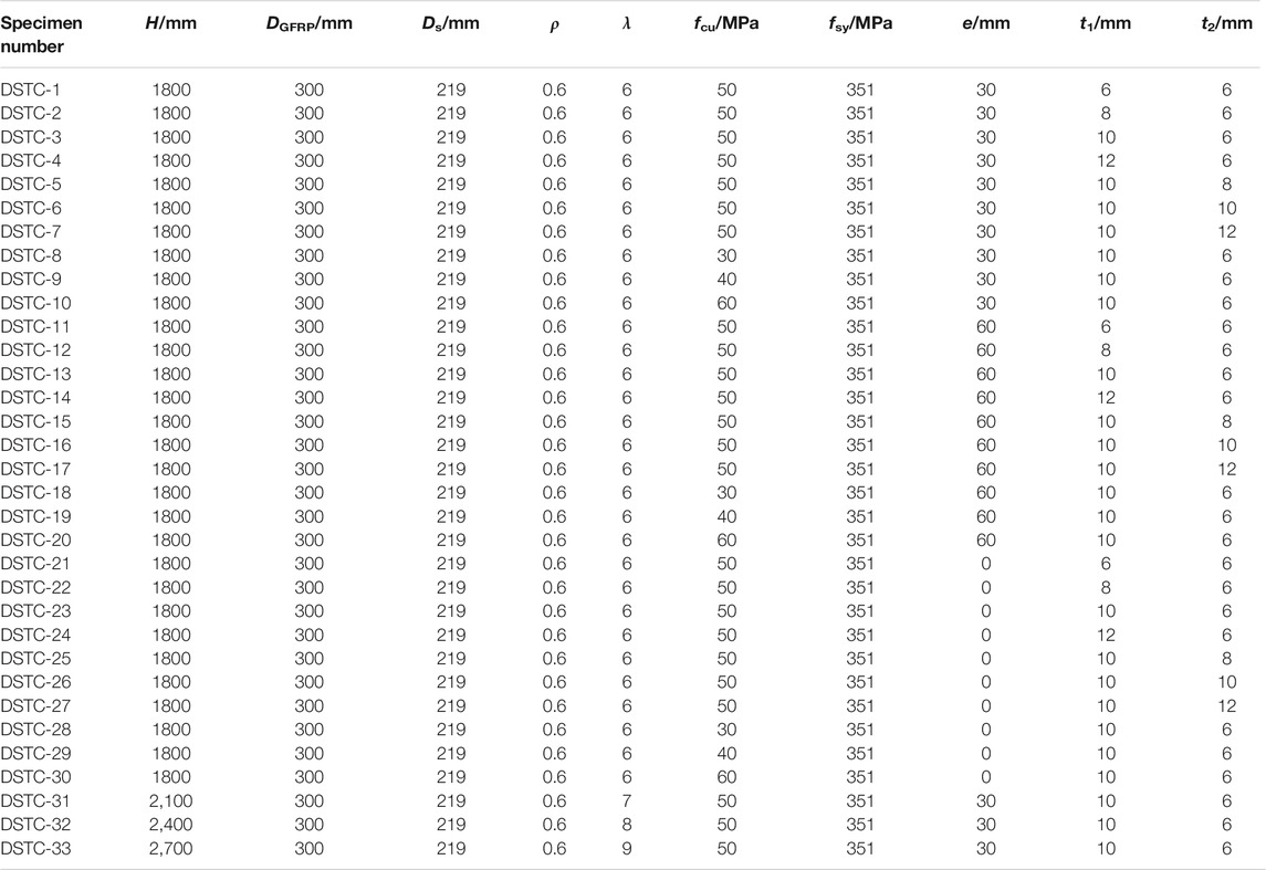
TABLE 1. Specific parameters of 33 specimens.
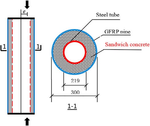
FIGURE 1. Hollow GFRP pipe-concrete-steel tube composite long columns.
GFRP is an orthotropic material which could provide little axial compression resistance, so only the axial tension effect of GFRP is considered in this paper. The linear elastic constitutive model is shown in Figure 2. The mechanical properties of GFRP pipes are shown in Table 2. The axial stress-strain relationship of GFRP is as follows:
Where
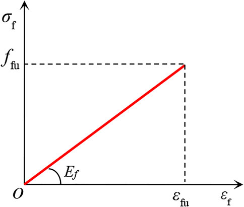
FIGURE 2. Constitutive model of GFRP pipe.

TABLE 2. Mechanical properties of GFRP pipe.
The constitutive model of confined concrete is given by Han et al. (2001), Teng et al. (2006), Mander et al. (1988) and Pagoulatou et al. (2014), and the comparisons of different constitutive models are shown in Figure 3. The constitutive model of confined concrete proposed by L. H. Han is adopted in this article and the plastic damage model of concrete is selected in the ABAQUS software.
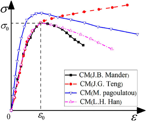
FIGURE 3. Different constitutive models of concrete.
The stress-strain relationship of concrete under uniaxial compression:
Where:
The stress-strain relationship of concrete under uniaxial tension:
Where,
The double-broken line elastoplastic constitutive model considering stress hardening is adopted as the constitutive model of the inner steel tube, as shown in Figure 4. The stress-strain relationship is shown in Eq. 14, where E1 is taken as 0.01Es.
Where, Es is the elastic modulus of the steel tube. E1 is the modulus of the plastic stage of the steel tube. fsy and ɛsy are the yield strength and its corresponding strain of the steel tube, respectively.
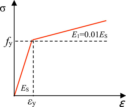
FIGURE 4. Bilinear constitutive model of steel tube.
Based on the finite element software ABAQUS, finite element model of the hollow GFRP pipe-concrete-high strength steel tube composite column is established. Eight-node three-dimensional solid elements (C3D8R) are adopted to simulate the steel tube, concrete and GFRP pipe. The interface contact among GFRP pipe, steel tube and concrete consisted of two aspects, including the hard contact in the normal direction and the frictional contact considering relative slip in the tangent direction, as shown in Figure 5. In the normal direction, in order to make the interaction surface fully contact, the hard contact is adopted. The interface pressure of the contact unit is p. In the tangent direction, shear stress τ can be freely transferred between the interface of steel tube and concrete. When the shear stress reaches the critical value of interface bond stress τbond, the interfacial bond stress failed, that is, GFRP pipe, steel tube and concrete began to slip relatively, as shown in Eq. 15. In this paper, the relative slip between the interface of steel tube and concrete is considered during the analysis process, and the friction coefficient µ is taken as 0.5 (Ji et al., 2020).
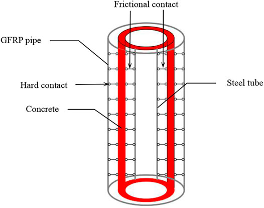
FIGURE 5. Material contact relationship of composite long columns.
Two reference points RP1 and RP2 are set at both ends of the specimens, and RP1 and RP2 are coupled with the degrees of freedom at the end sections of columns. In order to ensure that the eccentric compression columns exhibits the flexure only in the XOZ plane during the loading process, the degrees of freedom (UX, UY, URX, and URY) of the eccentric compression columns are restricted at the upper end, while the degrees of freedom (UX, UY, UZ, URX, and URY) are restricted at the lower end. Vertical displacement is applied to the reference point RP1 at the upper end of the column. In order to ensure the accuracy and efficiency of the model calculation, a suitable mesh density is selected firstly to analyze the model, and then the density mesh of the model is taken as 2 times to analyze again. By comparing the calculation results of the two meshing methods, the error between them is less than 5%, which could be used as a suitable meshing for the composite columns. The meshing of the finite element model is shown in Figure 6.

FIGURE 6. Meshing of finite element model.
In order to verify the rationality of the finite element modeling, four GFRP pipe-concrete-steel tube composite columns from the literature (Xu, 2013) are selected for finite element simulation in this paper, and the load-displacement relationship curves of the composite columns can be obtained. By comparing the results of existing tests, the rationality of the finite element modeling of the composite columns in this paper is verified. The specific parameters of four specimens are shown in Tables 3, 4, here fc and Ec are the axial compressive strength of concrete and the elastic modulus of concrete, respectively.
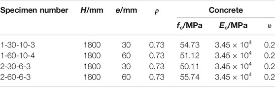
TABLE 3. Specific parameters of four specimens.
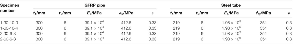
TABLE 4. Specific parameters of four specimens of GFRP pipe and steel tube.
The above modeling method is used to carry out numerical analysis for the eccentrical compression behavior of four test specimens, and the load-displacement relationship curves of the four specimens are obtained. The comparisons of the load-displacement curves between simulations and tests are shown in Figure 7. It can be seen by comparison that the trend of the test curves are basically consistent with that of the simulated curves, which are in good agreement. However, some specimens in the later plastic stage are in general agreement. The possible reason is that the concrete is regarded as an isotropic continuous element during the simulation analysis, while the concrete is regarded as a discrete element in the test. The ultimate eccentrical compression bearing capacity and ultimate displacement of the specimens can be extracted by load-displacement curves, as shown in Table 5.
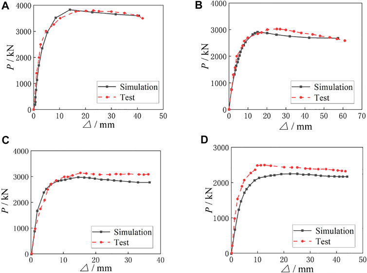
FIGURE 7. Comparisons of load-displacement curves between simulation and test. (A) Specimen 1-30-10-3. (B) Specimen 1-60-10-4. (C) Specimen 2-30-6-3. (D) Specimen 2-60-6-3.
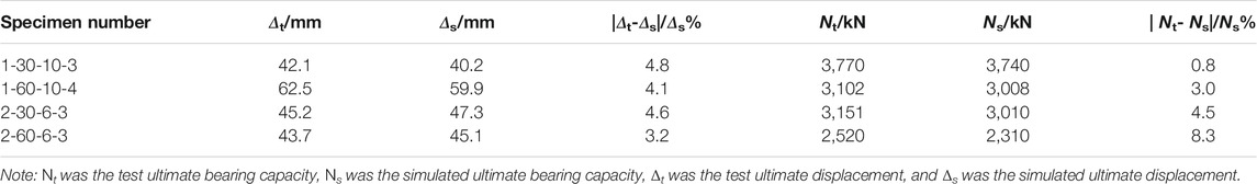
TABLE 5. Comparisons of ultimate eccentrical compression bearing capacity and ultimate displacement.
It can be seen from Table 5 that the maximum error between the simulated eccentrical compression ultimate bearing capacity (Ns) and the test ultimate bearing capacity (Nt) is less than 10%, which can be seen that the analytical results of the finite element simulations and the tests are in good agreement. The comparisons of the failure modes between the simulations and tests of four specimens are shown in Figure 8. It can be seen that the overall deformation and failure position of the simulated composite columns are basically the same as those of the test composite columns, which can verify the rationality and feasibility of the finite element modeling method.
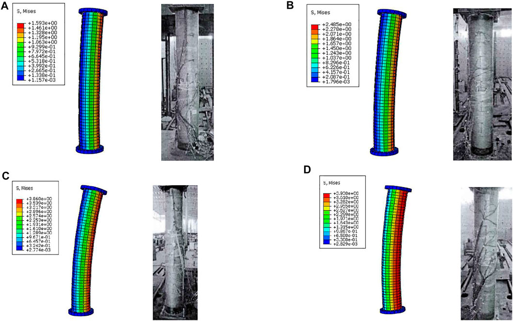
FIGURE 8. Comparisons of deformation between simulation and test for four specimens. (A) Specimen 1-30-10-3. (B) Specimen 1-60-10-4. (C) Specimen 2-30-6-3. (D) Specimen 2-60-6-3.
The comparisons of load-displacement curves of specimens with different t1 are shown in Figure 9, and the ultimate eccentrical compression bearing capacity (Ns) of the specimens is shown in Table 6. It can be seen from Figure 9 that the initial stiffness of the specimens is basically unchanged with the increasing of t1, and with the increasing of load, the stiffness of the specimens gradually increases. As can be seen from Figure 9A, when the eccentricity (e) is 30 mm and t1 increases from 6 to 8, 10 and 12 mm, respectively, Ns increases from 2979 to 3336kN, 3804 and 4564kN in turn, which increases by 12.0, 27.7 and 53.2%, respectively. As can be seen from Figure 9B, when e is 60 mm and t1 increases from 6 to 8, 10 and 12 mm respectively, Ns increases from 2472 to 2736kN, 3081 and 3698kN in turn, which increases by 10.7, 24.6 and 49.6%, respectively. As can be seen from Figure 9C, when e is 0mm, t1 increases from 6 to 8, 10 and 12 mm respectively, Ns increases from 3932 to 4404kN, 5022 and 6051kN in turn, which increases by 12.0, 27.7 and 53.9%, respectively. It can be concluded that Ns of the three groups of specimens show the same change regularity, that is, Ns increases gradually and the increase rate is larger with the increasing of t1. All specimens show good bearing capacity.
FIGURE 9. Comparisons of load-displacement curves for specimens with different GFRP thicknesses. (A) Load-displacement curves of group A specimens. (B) Load-displacement curves of group B specimens. (C) Load-displacement curves of group C specimens.

TABLE 6. Ultimate eccentrical compression bearing capacity of specimens with different thicknesses of GFRP pipe.
The comparisons of load-displacement curves of specimens with different t2 are shown in Figure 10, and the ultimate eccentrical compression bearing capacity (Ns) of the specimens is shown in Table 7. It can be seen from Figure 10 that the initial stiffness of the specimens is basically unchanged with the increasing of t2, while the ultimate eccentrical compression bearing capacity of the specimens increases gradually. As can be seen from Figure 10A, when the eccentricity (e) is 30 mm and t2 increases from 6 to 8, 10 and 12 mm, respectively, Ns increases from 3804 to 3961kN, 4381 and 4822kN in turn, which increases by 4.0, 13.2 and 21.1%, respectively. As can be seen from Figure 10B, when e is 60 mm and t2 increases from 6 to 8, 10 and 12 mm respectively, Ns increases from 3081 to 3248kN, 3589 and 3996kN in turn, which increases by 5.1, 14.2 and 22.9%, respectively. As can be seen from Figure 10C, when e is 0 mm and t2 increases from 6 to 8, 10 and 12 mm, respectively, Ns increases from 5022 to 5229kN, 5789 and 6361kN in turn, which increases by 4, 13.2 and 21.1%, respectively. It can be concluded that Ns of the three groups of specimens show the same change regularity, that is, Ns gradually increases and the increase rate is larger with the increase of t2. With the increasing of deformation, the curves tend to be horizontal and then begin to decrease slowly. All specimens show good bearing capacity.
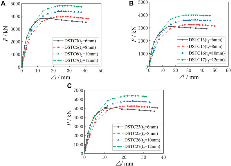
FIGURE 10. Comparisons of Load-Displacement Curves of Specimens with Different Steel Tube Thicknesses. (A) Load-displacement curves of group A specimens. (B) Load-displacement curves of group B specimens. (C) Load-displacement curves of group C specimens.
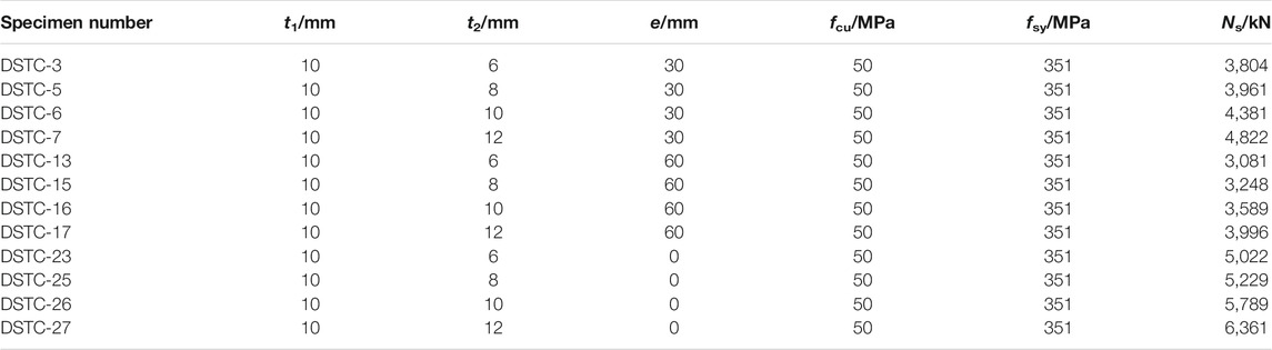
TABLE 7. Ultimate eccentrical compression bearing capacity of specimens with different thicknesses.
The comparisons of load-displacement curves of specimens with different fcu are shown in Figure 11, and the ultimate eccentrical compression bearing capacity of the specimens is shown in Table 8. It can be seen from Figure 11 that the initial stiffness of the specimens is basically unchanged with the increasing of fcu, and with the increasing of load, the stiffness of the specimens gradually increases. As can be seen from Figure 11A, when e is 30 mm and fcu increases from 30 to 40, 50 and 60 MPa, respectively, Ns increases from 2693 to 3112kN, 3804 and 4502kN in turn, which increases by 13.5, 29.2 and 40.2%, respectively. As can be seen from Figure 11B, when e is 60 mm and fcu increases from 30 to 40, 50 and 60 MPa, respectively, Ns increases from 2235 to 2546kN, 3081 and 3737kN in turn, which increases by 12.2, 27.5 and 40.2%, respectively. As can be seen from Figure 11C, when e is 0 mm and fcu increases from 30 to 40, 50 and 60 MPa, respectively, Ns increases from 3555 to 4075kN, 5022 and 5921kN in turn, which increases by 12.8, 29.2 and 40%, respectively. It can be concluded that Ns of the three groups of specimens show the same change regularity, that is, Ns gradually increases and the increase rate is larger with the increasing of fcu. When fcu reaches 60MPa, the growth rate of ultimate eccentrical compression bearing capacity begins to slow down. All specimens show good ductility and bearing capacity.
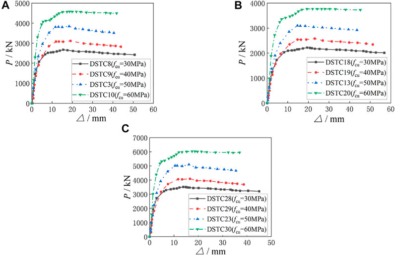
FIGURE 11. Comparisons of load-displacement curves of specimens with different concrete strengths. (A) Load-displacement curves of group A specimens. (B) Load-displacement curves of group B specimens. (C) Load-displacement curves of group C specimens.
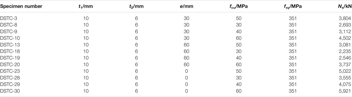
TABLE 8. Ultimate eccentrical compression bearing capacity of specimens with different compressive strengths of concrete cubes.
The comparisons of the ultimate eccentrical compression bearing capacity of multiple groups of specimens with eccentricities of 0, 30 and 60 mm are shown in Figure 12. It can be seen from Figure 12 that eccentricity was an essential part in the ultimate eccentrical compression bearing capacity of specimens. With the increasing of eccentricity, the ultimate eccentrical compression bearing capacity decreases gradually. Taking Figure 12A as an example, when t1 is 6 mm and e increases from 0 to 30mm and 60 mm respectively, Ns decreases from 3932 to 2979kN and 2472kN in turn, which decreases by 32 and 59%, respectively. When t1 is 8 mm and e increases from 0 to 30mm and 60 mm respectively, Ns decreases from 4404 to 3336kN and 2736kN in turn, which decreases by 32.4 and 60.7%, respectively. When t1 is 10 mm and e increases from 0 to 30mm and 60 mm, respectively, Ns decreases from 5022 to 3804kN and 3081kN in turn, which decreases by 32.1 and 63.0%, respectively. When t1 is 12 mm and e increases from 0 to 30mm and 60 mm, respectively, Ns decreases from 6051 to 4564kN and 3698kN in turn, which decreases by 42.4 and 75.8%, respectively. To sum up, the eccentricity can be regarded as the most important factor affecting the ultimate eccentrical compression bearing capacity of the specimens.
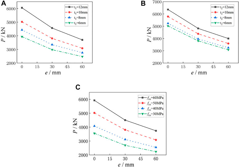
FIGURE 12. Comparisons of ultimate bearing capacity of specimens with different eccentricities. (A) Specimens with different GFRP thicknesses. (B) Specimens with different steel tube thicknesses. (C) Specimens with different concrete strengths.
The comparisons of load-displacement curves of specimens with different slenderness ratios are shown in Figure 13. It can be seen that the initial stiffness of the specimen decreases gradually with the increasing of slenderness ratio, and with the increasing of load, the curve deviates further and further from the coordinate axis, and the specimens have low ultimate eccentrical compression bearing capacity. As can be seen from Figure 13, when the slenderness ratio of the specimens increases from 6 to 7, 8 and 9, respectively, the ultimate eccentrical compression bearing capacity of the specimens decreases from 3804 KN to 3202, 2837 and 2689 KN in turn, which decreases by 15.8, 25.4 and 29.3%, respectively. It can be concluded that with the increasing of slenderness ratio, the ultimate eccentrical compression bearing capacity of the specimens decreases gradually and the decreasing amplitude becomes smaller and smaller, but the load-holding capacity becomes better and better.

FIGURE 13. Comparisons of load-displacement curves for specimens with different slenderness ratios.
The partial pressure (N)-deformation (Δ) characteristic curve of hollow GFRP pipe-concrete-high strength steel tube composite long column subjected to eccentric compression is shown in Figure 14. At the initial loading stage, N is small and the specimen is at the elastic stage (OA segment). The longitudinal inhomogeneous compressive strain of the composite column section basically maintains a linear relationship, which conforms to the plane-section assumption. With the increasing of N, the curve gradually deviates from the ordinate, and the stiffness of the specimen decreases, then the specimen enters the elastic-plastic stage (AB segment). The longitudinal inhomogeneous compressive strain of the composite column section increases gradually, but it still conforms to the plane-section assumption. With the further increasing of N, the radial strain of sandwich concrete is greater than that of steel tube and GFRP pipe, then the deformation of concrete starts to be constrained by steel tube and GFRP pipe, which shows that the specimen enters the plastic stage (BC segment) (Yu and Hu, 2014; Zhang et al., 2015; Shen, 2019). The sandwich concrete is under triaxial compression. The outer GFRP pipe is under radial compression and hoop tension, while the inner steel tube is subjected to both radial and hoop compression, and the micro-stress state of the cross-section element is shown in Figure 15. After the peak compression load, the axial strain of GFRP pipe and steel tube at the lower compression side changes from compressive strain to tensile strain, and the steel tube at the larger compression side yields, resulting in outer bulging deformation of specimen. Then, the specimen enters the load-holding stage (CD segment), finally the GFRP pipe at the mid-span compression side of the long column breaks circumferentially. The restraint effect on the concrete disappears, and the specimen is declared to fail. All specimens show good load-holding capacity and deformation capacity. The failure process of specimens presents certain characteristics, which belongs to ductile failure.

FIGURE 14. Typical N-Δ curve.
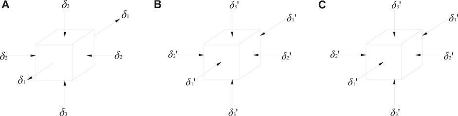
FIGURE 15. Micro-stress state of section element. (A) GFRP pipe. (B) Concrete. (C) Steel tube.
Since slenderness ratio and eccentricity have significant influence on the eccentric compression bearing capacity of hollow GFRP pipe -concrete-high strength steel tube composite long columns, the empirical coefficient method is adopted. Referred to the calculation formula of single-pillar bearing capacity in “Specification for Design and Construction of Concrete-filled Steel Tube Structures” (CECS28-90) (National Standards of the People’s Republic of China CECS28:901990), the calculation formula of the eccentric compression bearing capacity of hollow GFRP pipe-concrete-high strength steel tube composite long columns is given as follows:
Where,
The formula proposed in literature (Qian and Liu, 2006) is adopted as the calculation formula of axial compression capacity and slenderness ratio reduction coefficient of hollow GFRP pipe-concrete-steel tube composite short columns:
Where,
When the steel tube diameter-thickness ratio is greater than 20 for composite columns,
Where, A is the influencing factor considering the hollow ratio and the steel tube diameter-thickness ratio. Hollow ratio
In the literature (Qian and Liu, 2006), experimental data is used to fit the reduction coefficient
Where,
In order to consider the reduction factor of eccentricity, the calculation formula is used as follows:
Where,
The Eqs 17, 21, 22 are taken into Eq. 16 to obtain Eq. 24, and the calculation formula for the eccentric compression bearing capacity of the hollow GFRP pipe-concrete-high strength steel tube composite long columns is obtained.
The Eq. 24 is used to calculate the ultimate eccentric compression bearing capacity (
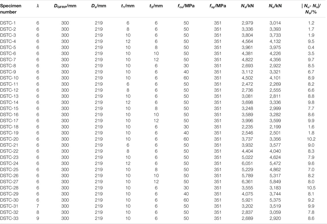
TABLE 9. Comparisons of Ns and Nu for 33 composite columns.

FIGURE 16. Comparisons of simulated and calculated bearing capacity of DSTC composite columns.
The finite element models of 33 hollow GFRP pipe-concrete-high strength steel tube composite long columns are established by finite element software ABAQUS, and the eccentric compression behavior analysis of the composite long columns is carried out. The load-displacement curves of the specimens can be obtained during the whole process. The influence regularity of the different parameters on the ultimate eccentric compression bearing capacity of specimens can be clarified. The specific conclusions can be drawn as follows:
1) Based on the stress-hardening double-line elastic-plastic constitutive model for steel, line elastic constitutive model for GFRP and constitutive model for confined concrete, the contact element is introduced to simulate the hollow GFRP pipe-concrete-high strength steel tube composite long columns. The load-displacement curves obtained from the tests and simulations are compared and the rationality of constitutive models and finite element modeling method can be verified.
2) With the increasing of the thickness of GFRP pipe and steel tube, the ultimate eccentric compression bearing capacity of specimens increases gradually. Under the double-layer constraint of GFRP pipe and steel tube, concrete can be under a state of triaxial compression. It can be seen that GFRP pipe has a significant constraint effect on concrete. With the increasing of the compressive strength of the cube concrete, the ultimate eccentric compression capacity of the specimens increases gradually. However, when the compressive strength of cube concrete reaches 60Mpa, the growth rate of ultimate eccentric compression capacity begins to slow down. The greater the eccentricity is, the greater the ultimate displacement of specimens is. However, the ultimate eccentrical compression bearing capacity decreases with the increasing of the eccentricity. The eccentricity can be regarded as the most important factor affecting the eccentric compression capacity of the specimens. With the increasing of slenderness ratio, the ultimate eccentric compression capacity decreases gradually.
3) The load-displacement curves of the composite long columns consist of four stages of elastic, elastoplastic, plastic and load-holding. Due to the restraint of GFRP pipe on concrete, the bearing capacity and deformation capacity of the specimens can be improved. When the specimens fail, due to the hoop fracture of GFRP pipe, the restraint effect on concrete disappears, and the specimens lose bearing capacity and fail. All specimens show good load-holding capacity and deformation capacity. The failure process of specimen presents certain characteristics, which belongs to ductile failure.
4) Based on the empirical coefficient method, the calculation formula of the eccentric compression bearing capacity of hollow GFRP pipe-concrete-high strength steel tube composite long columns can be obtained by statistical regression. It can provide theoretical support for the application of this kind of composite columns in practical engineering.
The original contributions presented in the study are included in the article/Supplementary Material, further inquiries can be directed to the corresponding authors.
JJ and WZ: writing, simulation; RW, HR, LZ, YL, LH, and CY: translation; LJ: simulation. All authors contributed to the article and approved the submitted version.
The authors are grateful the financial support received from the National Natural Science Foundation of China (Grant No. 51808173); The Natural Science Foundation of Heilongjiang Province (Grant No. LH 2020E018); Opening Fund for Key Laboratory of The Ministry of Education for Structural Disaster and Control of Harbin Institute of Technology (Grant No. HITCE201908); The Social Science Foundation of Hebei Province (Grant No. HB20GL055); the Northeast Petroleum University Guided Innovation Fund (Grant No.2020YDL-02) and the Research on Risk Identification and Emergency Management of Buildings from the Perspective of COVID-19 (Grant No. SQ2021115).
The authors declare that the research was conducted in the absence of any commercial or financial relationships that could be construed as a potential conflict of interest.
All claims expressed in this article are solely those of the authors and do not necessarily represent those of their affiliated organizations, or those of the publisher, the editors and the reviewers. Any product that may be evaluated in this article, or claim that may be made by its manufacturer, is not guaranteed or endorsed by the publisher.
Abdelkarim, O. I., and ElGawady, M. A. (2016). Behavior of Hollow FRP-concrete-steel Columns under Static Cyclic Axial Compressive Loading. Eng. Structures 123, 77–88. doi:10.1016/j.engstruct.2016.05.031
Abdelkarim, O. I., Mohamed, A. E., Gheni, A., Anumolu, S., and Abdulazeez, M. (2016). Seismic Performance of Innovative Hollow-Core FRP-concrete-steel Bridge Columns. J. Bridge Eng. 2, 04016120. doi:10.1061/(ASCE)BE.1943-5592.0000985
Afifi, M. Z., Mohamed, H. M., and Benmokrane, B. (2015). Theoretical Stress-Strain Model for Circular concrete Columns Confined by GFRP Spirals and Hoops. Eng. Structures 102, 202–213. doi:10.1016/j.engstruct.2015.08.020
Ahmed, M., Liang, Q. Q., Patel, V. I., and Hadi, M. N. S. (2018). Nonlinear Analysis of Rectangular Concrete-filled Double Steel Tubular Short Columns Incorporating Local Buckling. Eng. Structures 175, 13–26. doi:10.1016/j.engstruct.2018.08.032
AlAjarmeh, O. S., Manalo, A. C., Benmokrane, B., Karunasena, W., Mendis, P., and Nguyen, K. T. Q. (2019). Compressive Behavior of Axially Loaded Circular Hollow Concrete Columns Reinforced with GFRP Bars and Spirals. Construction Building Mater. 194, 12–23. doi:10.1016/j.conbuildmat.2018.11.016
Cao, P. P. (2013). Mechanical Behavior of Steel-Encased Concrete Filled FRP Tube Column under Unidirectional Eccentric Compression. Shenyang: Shenyang Jianzhu University.
Cheng, S. (2016). Behavior of Hybrid Columns of Concrete-filled Square Steel Tube with FRP-Confined Concrete Core under Axial Compression and Seismic Loading. Beijing: Tsinghua University.
Ekmekyapar, T., and Al-Eliwi, B. J. M. (2017). Concrete Filled Double Circular Steel Tube (CFDCST) Stub Columns. Eng. Struct 135, 68–80. doi:10.1016/j.engstruct.2016.12.061
Feng, P., Cheng, S., Bai, Y., and Ye, L. (2015). Mechanical Behavior of Concrete-filled Square Steel Tube with FRP-Confined Concrete Core Subjected to Axial Compression. Compos. Struct 123, 312–324. doi:10.1016/j.compstruct.2014.12.053
Fernando, D., Teng, J., Gattas, J., and Heitzmann, M. (2018). Hybrid Fibre-Reinforced Polymer-Timber Thin-Walled Structural Members. Adv. Struct. Eng. 21, 1409–1417. doi:10.1177/1369433217739709
Han, L. H., Tao, Z. C., and Liu, W. (2001). Concrete Filled Steel Tubular Structures from Theory to Practice. J. Fuzhou Univ. (Natural Sci. Edition) 6, 24–34.
Idris, Y., and Ozbakkaloglu, T. (2014). Flexural Behavior of FRP-HSC-Steel Composite Beams. Thin-Walled Struct 80, 207–216. doi:10.1016/j.tws.2014.03.011
Ji, J., Song, H., Jiang, L., Ren, H., Zhang, Y., and Liu, Y. (2021b). Tensile Performance of High Ductility Cementitious Composites with Recycled Powder from C&D Waste. Front. Mater. 8, 1–8. doi:10.3389/FMATS.2021.673752
Ji, J., Xu, Z., Jiang, L., Yuan, C., Zhang, Y., Zhou, L., et al. (2018). Nonlinear Buckling Analysis of H-type Honeycombed Composite Column with Rectangular Concrete-Filled Steel Tube Flanges. Int. J. Steel Struct. 18, 1153–1166. doi:10.1007/s13296-018-0084-0
Ji, J., Yang, M., Xu, Z., Jiang, L., and Song, H. (2021c). Experimental Study of H-Shaped Honeycombed Stub Columns with Rectangular Concrete-filled Steel Tube Flanges Subjected to Axial Load. Adv. Civil Eng. 2021, 1–18. doi:10.1155/2021/6678623
Ji, J., Yu, D. Y., and Jiang, L. Q. (2020). Research on Axial Compression Bearing Capacity of Different-Strength Concrete Filled Double Steel Tube Short Columns. Building Struct. 50, 121–129. doi:10.19701/j.jzjg.2020.05.021
Ji, J., Zhang, R., Yu, C., He, L., Ren, H., and Jiang, L. (2021a). Flexural Behavior of Simply Supported Beams Consisting of Gradient Concrete and GFRP Bars. Front. Mater. 8, 1–14. doi:10.3389/FMATS.2021.693905
Mander, J. B., Priestley, M. J. N., and Park, R. (1988). Theoretical Stress‐Strain Model for Confined Concrete. J. Struct. Eng. 114, 1804–1826. doi:10.1061/(asce)0733-9445(1988)114:8(1804)
National Standards of the People's Republic of ChinaCECS28:90 (1990). Specification for Design and Construction of Concrete-filled Steel Tubular Structures. Beijing: China Architecture & Building Press.
Pagoulatou, M., Sheehan, T., Dai, X. H., and Lam, D. (2014). Finite Element Analysis on the Capacity of Circular Concrete-filled Double-Skin Steel Tubular (CFDST) Stub Columns. Eng. Structures 72, 102–112. doi:10.1016/j.engstruct.2014.04.039
Qian, J. R., and Liu, M. X. (2006). Experiment of FRP-concrete-steel Double-Skin Tubular Long Columns under Axial Compressive Load, Concrete, 9, 31–34. CNKI:SUN:HLTF.0.2006-09-009.
Qian, J. R., Zhang, Y., and Zhang, W. J. (2015). Eccentric Compressive Behavior of High Strength Concrete Filled Double-Tube Short Columns. J. Tsinghua Univ. (Natural Sci. Edition) 1, 1–7. doi:10.16511/j.cnki.qhdxxb.2015.01.001
Shen, Q. H. (2019). Research on the Eccentric Compressive Behavior of CFRP Partially-Wrapped Circular CFST Stub Columns. Ind. Construction 49, 192–199. doi:10.13204/j.gyjz201910032
Teng, J.-G., Wang, Z., Yu, T., Zhao, Y., and Li, L.-J. (2018). Double-tube concrete Columns with a High-Strength Internal Steel Tube: Concept and Behaviour under Axial Compression. Adv. Struct. Eng. 21, 1585–1594. doi:10.1177/1369433217746838
Teng, J. G., Yu, T., Wong, Y. L., and Dong, S. L. (2007). Hybrid FRP-concrete-steel Tubular Columns: Concept and Behavior. Construction Building Mater. 21, 846–854. doi:10.1016/j.conbuildmat.2006.06.017
Wang, H.-P., Ni, Y.-Q., Dai, J.-G., and Yuan, M.-D. (2019b). Interfacial Debonding Detection of Strengthened Steel Structures by Using Smart CFRP-FBG Composites. Smart Mater. Struct. 28, 115001. doi:10.1088/1361-665X/ab3add
Wang, H., and Dai, J.-G. (2019a). Strain Transfer Analysis of Fiber Bragg Grating Sensor Assembled Composite Structures Subjected to thermal Loading. Composites B: Eng. 162, 303–313. doi:10.1016/j.compositesb.2018.11.013
Xu, P. (2013). Experimental Study on Capacity of FRP-concrete-steel Double-Skin Tubular Columns. Zhejiang: Zhejiang University.
Yu, D. Y. (2020). Research on Axial Compression and Seismic Performance of Solid-Web GFRP-concrete-steel Tube Composite Column. Daqing: Northeast Petroleum University. doi:10.26995/d.cnki.gdqsc.2020.000549
Yu, T., Hu, Y. M., and Teng, J. G. (2014). FRP-confined Circular Concrete-filled Steel Tubular Columns under Cyclic Axial Compression. J. Constructional Steel Res. 94, 33–48. doi:10.1016/j.jcsr.2013.11.003
Zhang, B., Teng, J. G., and Yu, T. (2015). Experimental Behavior of Hybrid FRP-concrete-steel Double-Skin Tubular Columns under Combined Axial Compression and Cyclic Lateral Loading. Eng. Struct 99, 214–231. doi:10.1016/j.engstruct.2015.05.002
Keywords: hollow GFRP pipe-concrete-high strength steel tube composite columns, eccentricity, abaqus, constitutive model, bearing capacity subjected to eccentric load
Citation: Ji J, Zeng W, Wang R, Ren H, Zhang L, Liu Y, Jiang L, He L, Lin Y and Yu C (2021) Bearing Capacity of Hollow GFRP Pipe-Concrete-High Strength Steel Tube Composite Long Columns Under Eccentrical Compression Load. Front. Mater. 8:768877. doi: 10.3389/fmats.2021.768877
Received: 01 September 2021; Accepted: 13 September 2021;
Published: 27 September 2021.
Edited by:
Huaping Wang, Lanzhou University, ChinaCopyright © 2021 Ji, Zeng, Wang, Ren, Zhang, Liu, Jiang, He, Lin and Yu. This is an open-access article distributed under the terms of the Creative Commons Attribution License (CC BY). The use, distribution or reproduction in other forums is permitted, provided the original author(s) and the copyright owner(s) are credited and that the original publication in this journal is cited, in accordance with accepted academic practice. No use, distribution or reproduction is permitted which does not comply with these terms.
*Correspondence: Ruili Wang, emVuZ3dlbmRleXhAMTYzLmNvbSYjeDAwMDI2O2hhaXJzcA==; Liangqin Jiang, amlhbmdsaWFuZ3FpbjE5NzhAMTYzLmNvbQ==
Disclaimer: All claims expressed in this article are solely those of the authors and do not necessarily represent those of their affiliated organizations, or those of the publisher, the editors and the reviewers. Any product that may be evaluated in this article or claim that may be made by its manufacturer is not guaranteed or endorsed by the publisher.
Research integrity at Frontiers
Learn more about the work of our research integrity team to safeguard the quality of each article we publish.