 Xiangyu Zhang1
 Qing Xia
 Ping Xiang
94% of researchers rate our articles as excellent or good
Learn more about the work of our research integrity team to safeguard the quality of each article we publish.
Find out more
ORIGINAL RESEARCH article
Front. Mater., 22 November 2021
Sec. Structural Materials
Volume 8 - 2021 | https://doi.org/10.3389/fmats.2021.761376
This article is part of the Research TopicAdvanced Cementitious Materials and Structures Under Extreme ConditionsView all 4 articles
Steel-reinforced concrete (SRC) special-shaped column and beam frame structure is a special structural form that can meet the requirements of high bearing capacity and satisfy the esthetic requirement of buildings. In this study, a new joint design approach is adopted to focus on the seismic behavior of SRC special-shaped column and reinforced concrete (RC) beam joints under low-cyclic double-directional reactions through pseudo-static tests with a controlled stirrup distance. The joints of SRC specimens were compared with those of RC specimens by controlling the area of steel and reinforcement, and hysteresis cycle skeleton curves and load and strain hysteresis cycles were analyzed. The specimen with profiled steel was found to have better energy dissipation capacity. The energy dissipation capacity and stiffness degradation of the nodes were analyzed. The test results showed that the energy dissipation capacity of the SRC joints was better than that of the conventional concrete column joints, and the stiffness degradation of RC joints was more significant than that of SRC joints.
Steel-reinforced concrete (SRC) special-shaped columns are more esthetically pleasing than the traditional rectangular columns of frame structures and can meet the requirements of architectural design. Compared with traditional rectangular columns, the application of special-shaped columns is more complicated and restricted. Special section shapes such as L-shaped, cross-shaped, T-shaped, and Z-shaped are usually used instead of the traditional rectangular section, so the ductility, bearing capacity, and seismic performance of shaped columns, especially the structural joints, are of great concern (Park, 2002). The earthquake performance of these joints will directly affect the seismic resistance of the entire structure, and the failure of these joints is usually one of the causes of damage to the entire structure. According to earthquake records, most of the damages to frame structures occur at the joints or are caused by the fracture of the joints. Since joints are a vulnerable part of earthquakes, the study of joints has attracted the attention of scholars all over the world. Experimental studies on the shear bearing capacity and seismic performance of reinforced concrete (RC) beam and column joints are necessary (Ma et al., 2019; Cao et al., 2021; Deng et al., 2021). Many researchers have conducted experimental studies on shear capacity, seismic performance, or mechanical behavior of square RC columns (Huang et al., 2019), T-shaped (Zhang et al., 2019; Deng et al., 2021), L-shaped (Chen et al., 2021a; Chen et al., 2021b), and other shaped columns connected with reinforced concrete beams.
Steel-reinforced concrete (SRC) special-shaped columns with good seismic performance must not only meet the load requirements in the service phase but also maintain the ability to transmit vertical loads under predetermined seismic action when the part of the joint connection becomes inelastic or elasto-plastic after repeated deformation. It is, therefore, necessary to study the mechanical properties of combined structures under low repeated loads. An experimental study on shear reinforcement in CRTS II slab ballastless track under low cyclically repeated loads was carried out by Feng et al. (2020). In order to assess the seismic and hysteresis behavior of structural joints, cyclic loading tests are considered to be an effective method in a range of studies (Karabinis, 2002; Chun et al., 2007; Said, 2009; Sasmal et al., 2010; Metelli et al., 2015). Many researchers have now carried out cyclic loading test studies for reinforced concrete T-columns with reinforced concrete beams (Xiang et al., 2017), strand-inserted precast concrete beam and column joints (Yu et al., 2020), non–core-anchored concrete-encased CFST wall and RC coupling beam joints (Zhou et al., 2020), concrete-encased steel column and steel beam joints (Chu et al., 2018), steel truss–reinforced composite joints (Deng et al., 2018a), and a range of other combined structures (Chen et al., 2015a; Chen et al., 2015b; Xu et al., 2019).
When the frame becomes elasto-plastic, with some significant deformation and cracking at the joints, it is still capable of transmitting stresses, shear forces, and bending moments. These require more research into the degradation of load carrying capacity and ductility, as well as the degradation of the strength of the reinforcement after yielding at the joint, to ensure the safety of the structure. Joints are an integral part of shaped column and beam structural frames, undertaking important tasks such as moment distribution, force transfer, and collapse resistance under seismic excitation (Chen et al., 2015). The structural behavior of combined structures under seismic loading was investigated through a series of hybrid frame joints between composite columns and steel beams (Chu et al., 2020), precast concrete columns with grouted corrugated sleeves and decoupled longitudinal reinforcement (Chen et al., 2019), reinforced concrete cruciform columns (Chen and Liu, 2018), and shear walls with steel trusses connecting the beams (Deng et al., 2018b; Deng et al., 1311). It was found that the hysteretic behavior was significantly improved for shear walls with steel truss connecting the beams under seismic loading and that the joints generally performed well under seismic action.
This study presents an SRC special-shaped column and RC beam joint, which adopts a new form of reinforcement: a circular steel tube as the core with some structural steel around it. The reinforcement on the beam is evenly arranged along both sides in height, and the reinforcement extends into the column for anchoring along the structural steel at the joint. There were four specimens in the test, three of which were beam joint specimens for reinforced concrete-shaped columns, and the other was a reinforced concrete-shaped column and beam joint specimen. In this test, the proportion of hoop reinforcement was used as a design parameter for the variation of these specimens. The energy dissipation capacity and joint stiffness degradation behavior of the proposed joints under low-cyclic load tests were analyzed by plotting hysteresis curves and calculating loop stiffness according to the test. The seismic performance of the joints was also analyzed to demonstrate the effectiveness of the joint design.
As for the seismic-resistant property test, most tests use single beam with mid-side joints as specimens. This test aims at a more precise simulation of the stress condition of the corner joint under a double-direction earthquake, so we used a twin beam with mid-side joints as a specimen and exerted a double-direction low-frequency cyclic load. This test has four specimens with an aim to simulate the stress condition of the corner joint under a double-direction earthquake. The stereogram of specimens is shown in Figure 1. Table 1 shows some terms, symbols, and their notes in the research (Xiang et al., 2017).
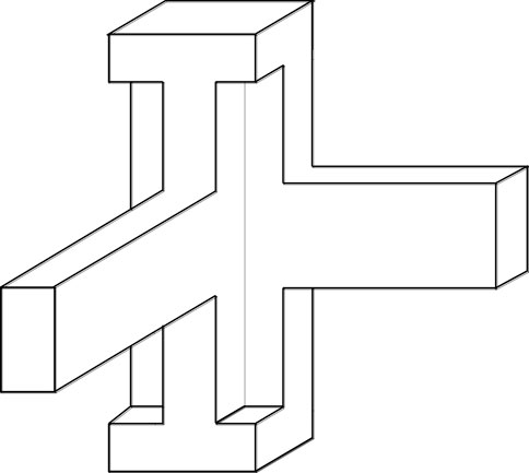
FIGURE 1. Stereogram of specimens.
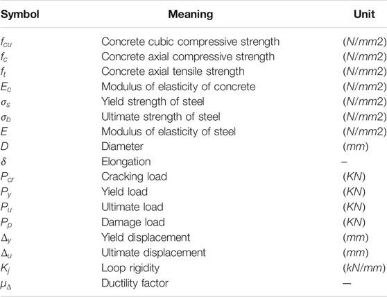
TABLE 1. Some of the terms covered in this article.
There are four specimens this time, and their serial numbers are JD-1, JD-2, JD-3, and JD-4. Each specimen has two beams to link with the special-shaped column, and the intersection is a joint core area. To distinguish them more easily, they are named beam① and beam② based on the different loading locations. Dimension of sections and material of bars are shown in Table 2.
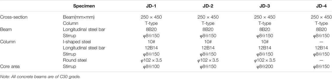
TABLE 2. Details of specimens (Xiang et al., 2017; Xiang et al., 2019).
Three-dimensional drawing of specimens is as shown in Figure 2. The column cross-sectional dimensions and cross-sectional reinforcement of specimens JD-1, JD-2, and JD-3 are shown in Figures 3, 4. For easy loading, each specimen is designed to have a rectangular chapiter. In the chapiter, φ12@60 and φ12@80 close-packed bar mats are crossly arranged. The reinforcement of column capital is as shown in Figure 5 to ensure that the chapiter can reasonably transmit the forces to the column. According to the strength theory, a total of four HRB335 bars with a diameter of 25 and 20 mm are arranged at beam’s top and bottom of all specimens, as shown in Figures 6, 7, so as to ensure that the loads are within the scope of the servo-loaded actuator when the beam end and joint are destroyed. The column section reinforcement of specimen JD-4 is shown in Figure 8, the overall reinforcement and section dimensions of specimens JD-1, JD-2, and JD-3 are shown in Figures 9, 10 (Xiang et al., 2017), and the overall reinforcement and section dimensions of specimen JD-4 are shown in Figures 11, 12 (Xiang et al., 2017).
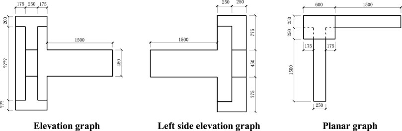
FIGURE 2. Three-dimensional drawing of specimens (Xiang et al., 2017; Xiang et al., 2019).
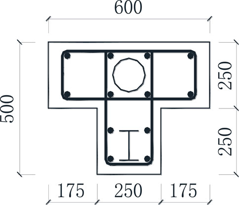
FIGURE 3. Column cross-sectional dimensions of specimens JD-1–JD-3 (Xiang et al., 2017; Xiang et al., 2019).
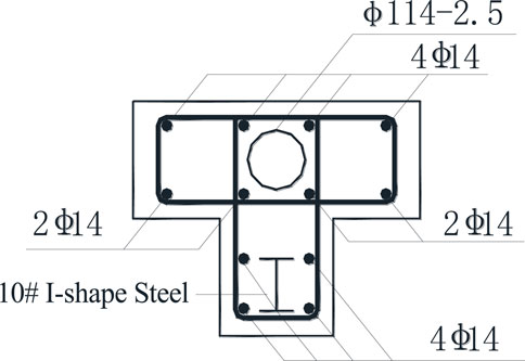
FIGURE 4. Column section reinforcement of specimen JD-1–JD-3 (Xiang et al., 2017; Xiang et al., 2019).
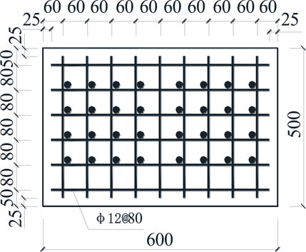
FIGURE 5. Reinforcement of column capital (Xiang et al., 2017; Xiang et al., 2019).

FIGURE 6. Beam section reinforcement of specimens JD-1–JD-3 (Xiang et al., 2017; Xiang et al., 2019).
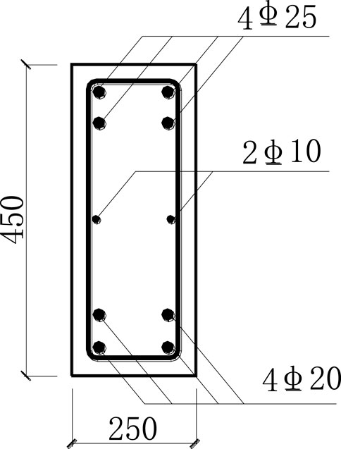
FIGURE 7. Beam section reinforcement of specimens JD-4 (Xiang et al., 2017; Xiang et al., 2019).
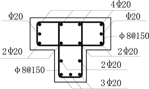
FIGURE 8. Column section reinforcement of specimen JD-4 (Xiang et al., 2017; Xiang et al., 2019).
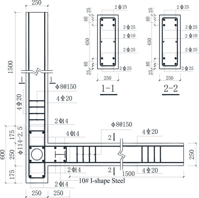
FIGURE 9. Section of specimen JD-1–JD-3 (Xiang et al., 2017; Xiang et al., 2019).
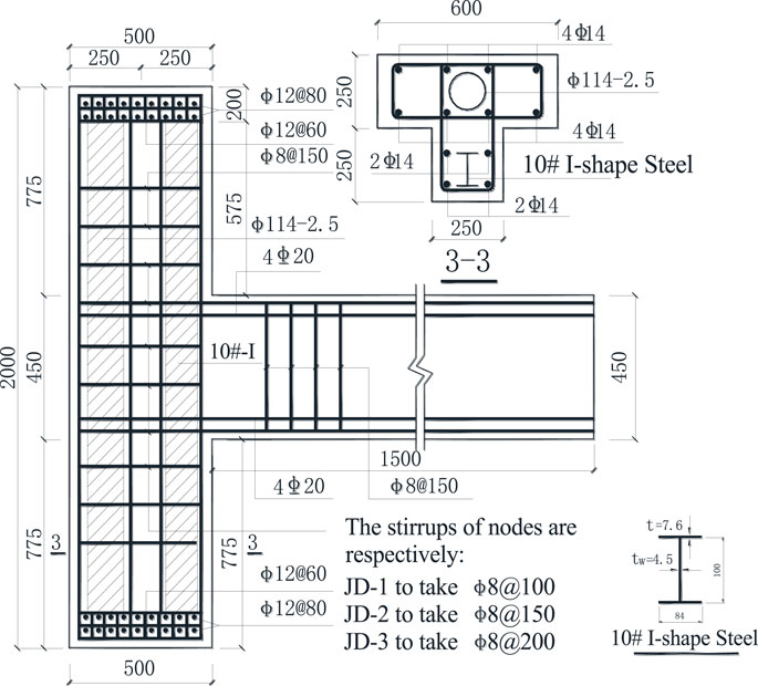
FIGURE 10. Reinforcement of specimen JD-1–JD-3 (Xiang et al., 2017; Xiang et al., 2019).
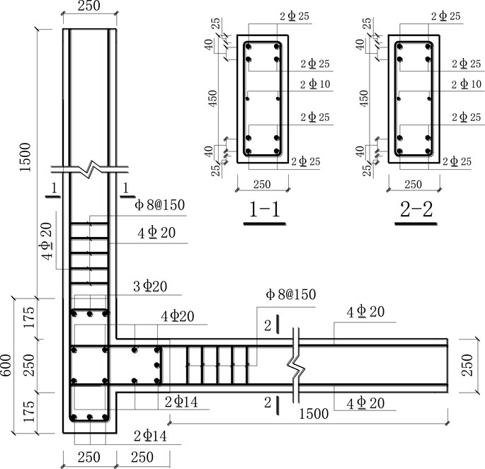
FIGURE 11. Section of specimen JD-4 (Xiang et al., 2017; Xiang et al., 2019).
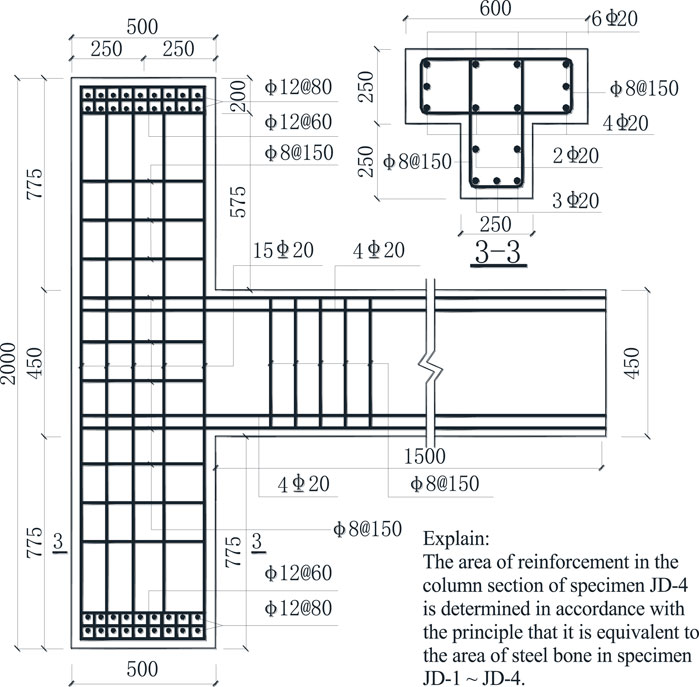
FIGURE 12. Reinforcement of specimen JD-4 (Xiang et al., 2017; Xiang et al., 2019).
All the specimens are made up of C30 concrete and are cured for 28 days as stated. In order to test the mechanical properties of concrete, three cubic standard test specimens (150 × 150×150) are left when each specimen is poured. To ensure that they have the same strength, the test specimens should be cured in open air under same conditions, and it should be the same day when we measure their compressive strength and do the test. Three rebar specimens used in the test should be left to measure their strength indexes and the stress and strain curve. Total 60 concrete strain gauges and rebar strain gauges are placed on each specimen’s special area, such as fissile parts at the joint area, and longitudinal reinforcements in the beam, stirrups, and steel ribs at the joint area.
When concreting the specimens and strapping the framework of bars, few materials were retained to test the actual mechanical property indexes; the results are listed in Tables 3, 4 (Xiang et al., 2017).
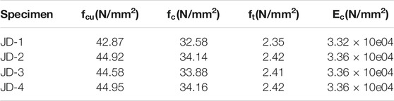
TABLE 3. Mechanical behavior of concrete (Xiang et al., 2017; Xiang et al., 2019).
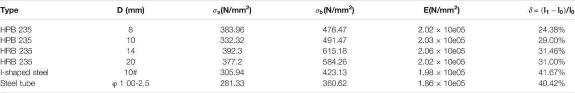
TABLE 4. Mechanical behavior of steel bars (Xiang et al., 2017; Xiang et al., 2019).
A common reinforcement concrete special-shaped column joint specimen JD-4 and steel-reinforced concrete special-shaped column joint specimen JD-1–JD-3 with a circular steel tube and structural steel inside are designed to compare their mechanical properties under a low-frequency cyclic load. By changing the ratio of stirrups in the core area, we can get the rule influenced by indexes and draw some relevant hysteretic curves. This test used an electro-hydraulic servo structure test machine to exert a double-direction low-frequency cyclic load.
The test devices are shown in Figure 13 (Xiang et al., 2017). A pseudo-static test was adopted. To ensure that the specimens can move horizontally with freedom under vertical and horizontal loads, a free slidable hinge was installed between the oil and pressure jack, which provided a vertical load at the chapiter and the upper rigid beam.
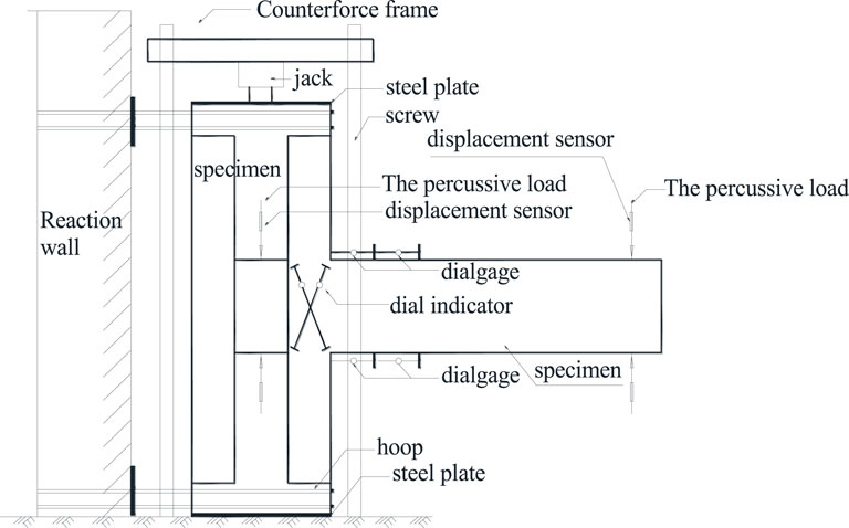
FIGURE 13. Experimental equipment (Xiang et al., 2017; Xiang et al., 2019).
To simulate the double-direction earthquake effect accurately and effectively and put the joint area into the worst condition, this test adopted a system where the low-frequency cyclic load was exerted step-by-step from both ends of the beam. The test site is as shown in Figure 14 (Xiang et al., 2017). As for the choice of the axial force, there are two tests: with it or without it. Specimen JD-1 was tested without the axial force. The other three were tested with the axial force exerted by the oil and pressure jack on the chapiter.
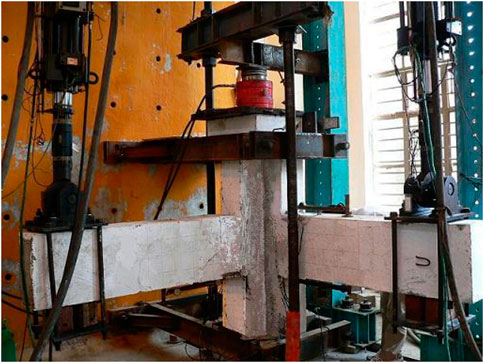
FIGURE 14. Test field loading devices (Xiang et al., 2017; Xiang et al., 2019).
The axial force should be exerted first and maintained stable when the load was repeatedly exerted. We used geometrical alignment to ensure the axial force was at the center of the section, and the predetermined axial force would be fully exerted 2–3 times. The loads on four specimens are no axial force on JD-1, 1000kN axial force on JD-2, 800kN axial force on JD-3, and 800kN axial force on JD-4. The loads were exerted on the chapiter by an oil and pressure jack. We used a load–displacement hybrid control as a loading criterion, and it was divided into two stages, as shown in Figure 15 (Xiang et al., 2017).
Stage 1: Load Controlling Stage
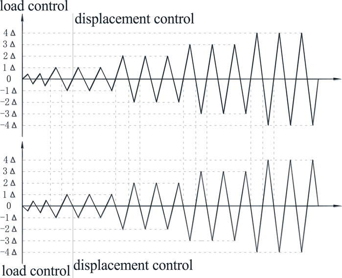
FIGURE 15. Loading criterion (Xiang et al., 2017; Xiang et al., 2019).
This stage is a small deformation stage before the specimens are exerted with calculated yielding loads. Next is the displacement controlling stage.
Stage 2: Displacement Controlling Stage
This stage appears after the specimens have yielded. Furthermore, the loads will be exerted three times circularly for each displacement grade.
This test used a resistance strain gauge to measure the strain of main reinforcement, and they were mainly arranged at the junction section of the beam end and column surface. Details are shown in Figure 16 (Xiang et al., 2017). To observe the force condition of stirrups, resistance strain gauges were used to measure the strain of stirrups in the plastic hinge area and joint core area. To observe the force condition of steel ribs in the joint area, rebar strain gauges were stuck along both the vertical diameter directions outside the steel tube and the flange and web of structural steel to measure the strain. The specific arrangement is shown in Figure 17 (Xiang et al., 2017). The arrangement of strain gauges is shown in Figure 18. Deflection data were measured by displacement sensors located on the actuator and then were transmitted to the computer. The computer automatically gathered deflection data under different loads.
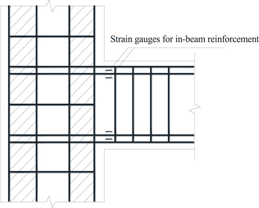
FIGURE 16. Distribution of strain gauges in beam (Xiang et al., 2017; Xiang et al., 2019).
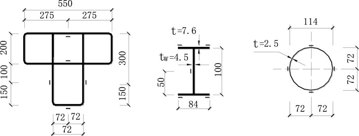
FIGURE 17. Distribution of strain gauges of stirrups shape steel and tube (Xiang et al., 2017; Xiang et al., 2019).
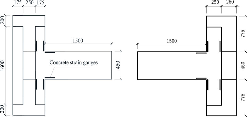
FIGURE 18. Distribution of concrete strain gauges.
For specimen JD-1, the space between stirrups in the joint core area is 100mm, and there are not any axial forces on the column top. In the first circulation, beam① suffered force downward, while beam② suffered force upward. As we observed from the test, when the load made the specimen yield for the first time, a crack spanning about 0.1 mm appeared in the joint area near the end of the beam. It was about 45°, drawing close gradually to the core area and expanding along the diagonal. When the displacement ductility factor
In the initial loading period, before cracks at joint appeared, steel ribs in the joint core area, where appeared some vertical displacement, had coordinating deformation with concrete. Shear deformation was subtle, and the joint core area was basically in the elastic stage. Before the destruction of the specimen, crossed diagonal cracks appeared in the joint core area. The cracks passed the intersection of diagonals, but the width of cracks did not grow apparently and the rigidity did not decline apparently. With the growth of the displacement ductility factor, concrete at the plastic hinges at the beam end began to peel off and the bearing capacity began to decline. The specimen was not destroyed until the bearing capacity declined to 80% of the maximum in the whole test.
Specimen JD-3 was the one which had the maximum stirrups space in the joint core of the three specimens. The space between stirrups was 200 mm. We kept the axial compression ratio constant and exerted 800 kN force. In the initial period, the test process was similar to that of the last two specimens. First, loads controlled the test and each load degree was 25 kN. In the first circulation, we paid attention to capture the cracking load, and it was 35 kN downward and 50 kN upward for beam①. The first crack appeared at the beam end and was not wide. Cracking load of beam② were 35 kN upward and 50 kN downward. In the end, when the bearing capacity declined to less than 80% of the maximum bearing capacity, the specimen was destroyed. Specimen JD-3 had fewer stirrups at joint, but its shearing capacity was still good enough in the joint core area.
Specimen JD-4 is the only contrastive joint specimen. By comparison, we found that the joint of the steel-reinforced concrete special-shaped column and reinforced concrete beam had relatively small crack width and large stiffness. In the displacement control stage, the larger displacement in the yield displacement of the first forward and reverse loading stage is used as the control displacement, and the displacement control at the same level is cycled three times. We can tell from the circulations that under the same displacement controlling degree, the joint’s bearing capacity of reinforced concrete special-shaped column and beam declined apparently and faster than that of steel-reinforced concrete special-shaped column and reinforcement concrete beam. When the displacement reached triple the yielding displacement, the plastic hinges at the beam end were destroyed badly and the protective layer of concrete began to peel off. Then the bearing capacity declined to less than 80% of the maximum bearing capacity, and the specimen was destroyed. This was the end of the test.
Based on the measured contents, we analyzed the data and got main data of the four specimens in the test. The data are listed in Table 5.
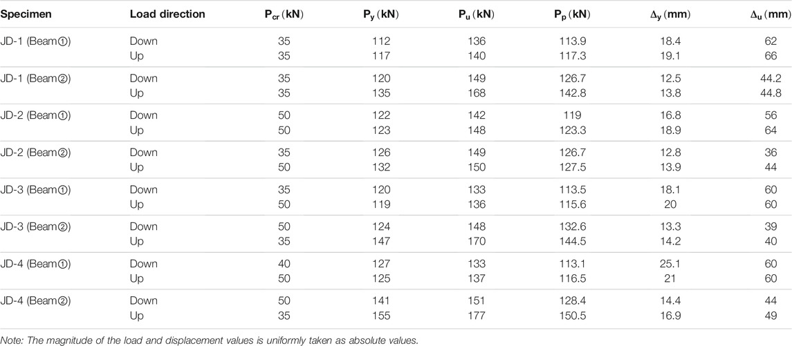
TABLE 5. Main data of the experiment.
Because of the influence of repeated loads, the hysteretic curve sufficiently reflected the bearing capacity, rigidity, ductility, energy-absorbing capacity, and energy-dissipating capacity, which are essential criterions on anti-seismic property analyses. By linking the deformation peaks in various circulation of the hysteretic curve, the envelope line of the hysteretic curve, which is called the skeleton curve, is drawn. Therefore, the seismic-resistant property of reinforced concrete special-shaped column joints can be analyzed by the skeleton curves, as shown in Figure 19.
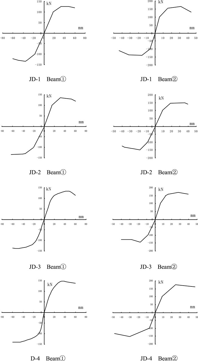
FIGURE 19. Skeleton curve of hysteretic loop of load and deflection at beam end.
The hysteresis loops of the load and strain of the longitudinal reinforcement at the end of the beam are shown in Figure 20. The hysteresis loops of the load and strain of the stirrups at the joint core drawn from the test results are shown in Figure 21.
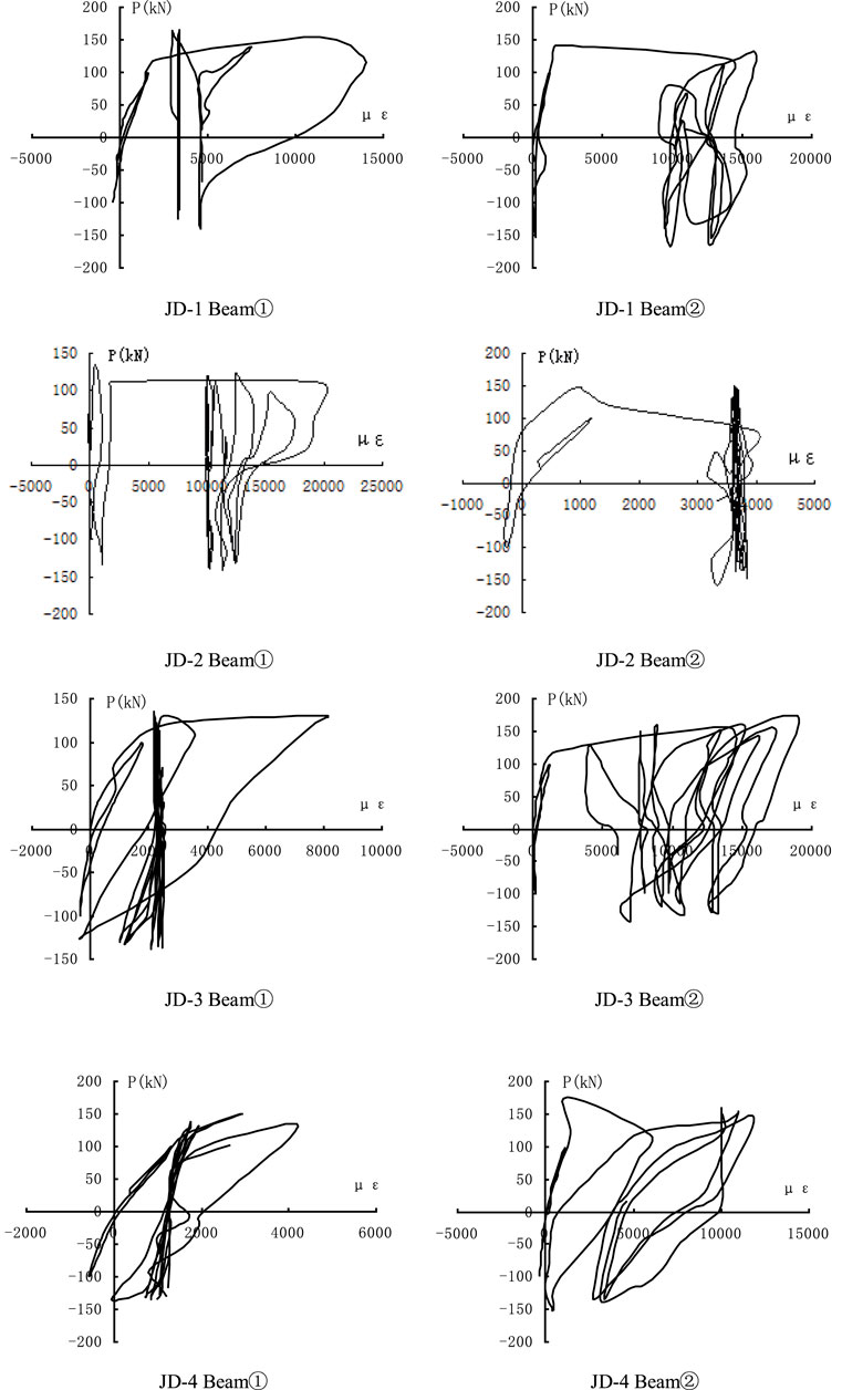
FIGURE 20. Hysteretic loop of load and strain of longitudinal bars at beam end.
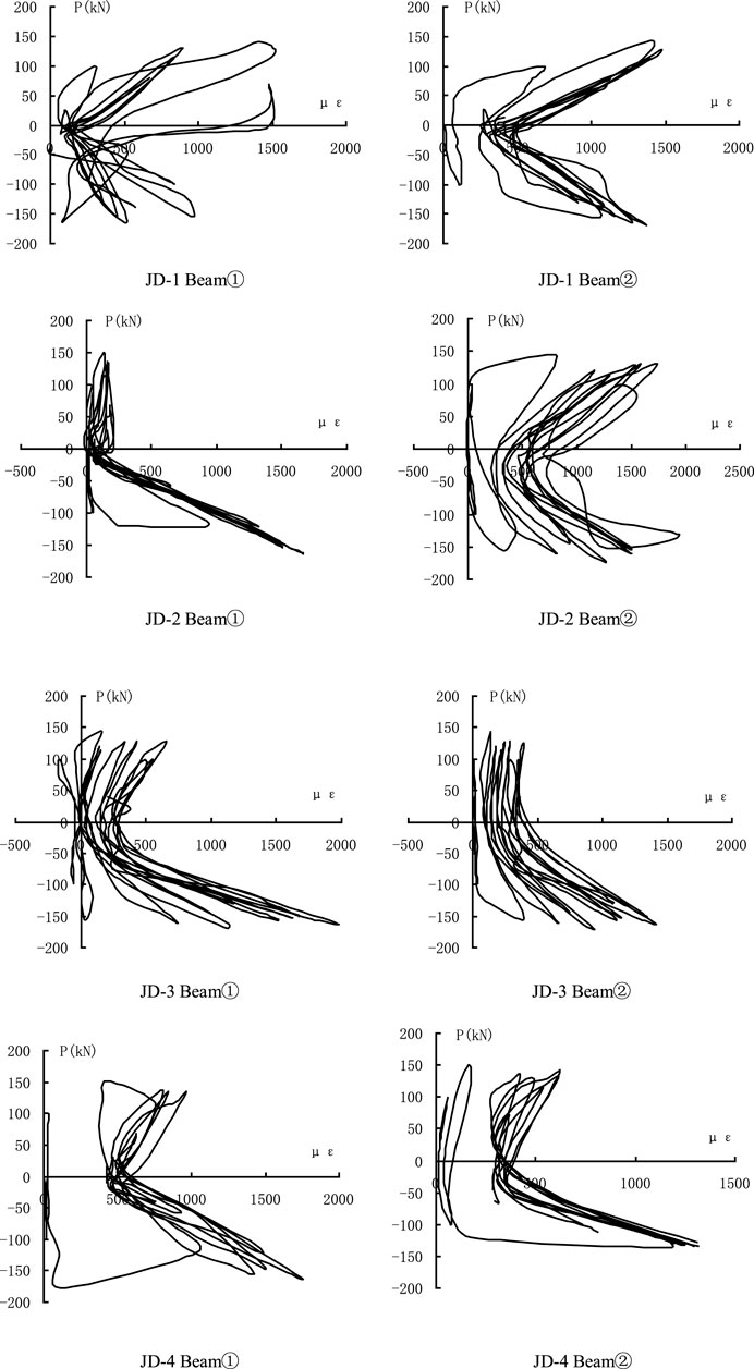
FIGURE 21. Hysteretic loop of load and strain of stirrup at joint’s core.
As we can tell from the figure, structural steel’s hysteretic loop of load and strain at the join core is similar to that of stirrups. In the initial loading period, strain is small and grows linearly. As the loads are repeatedly exerted, structural steel’s strain goes through a repeated process, where it becomes less and then larger, when the loads repeatedly transfer from the maximum to 0 and then to the reversed minimum. It proved that structural steel has the same effect as stirrups on constraining concrete. No matter forward or reversed, when the loads reach the peaks, the constraining effect of structural steel and stirrups reached its peak, which means strains of structural steel and stirrups reached the peaks. As the loads are repeatedly exerted, constrain capacity of structural steel and shear forces it takes change repeatedly. The hysteretic loop of the load and strain of shape steel of each specimen is falcate, as shown in the figure.
This study recorded some important data and the process of crack growth and destruction. We drew relevant hysteretic curves and compared the hysteretic loop of steel-reinforced concrete special-shaped column and reinforced concrete special-shaped column and beam joints with that of common reinforced concrete special-shaped column and beam joints. It is found that the former has a plumper hysteresis loop and presents better energy dissipation capacity and ductility than the latter. There are also analyses on strain hysteretic properties of structural steel and steel bar and the strain of rebars in JD-4, which are arranged based on the equivalent area criterion in the study. The result proves that structural steel and concrete in the core steel tube have positive effect on joint’s shear capacity in the work process.
In the condition that the displacement amplitude is constant, rigidity declines as the loads are exerted repeatedly and it is called rigidity degeneration. To show the rigidity degeneration property under low-frequency cyclic load, we can use three times the loop rigidity with the same displacement ductility coefficient to represent it. Definition of loop rigidity is given as follows:
where
Loop rigidity calculated by the displacement ductility coefficient is shown in Table 6. It can be seen from Table 6 that the loop rigidity declines as the multiple of displacement controlling grows, which reflects the rigidity degeneration of joints under a repeated earthquake effect. The rigidity degeneration of common reinforced concrete special-shaped column joint is more apparent than that of steel-reinforced concrete special-shaped column, which proves that steel ribs at joint has a positive effect in the anti-shearing process.
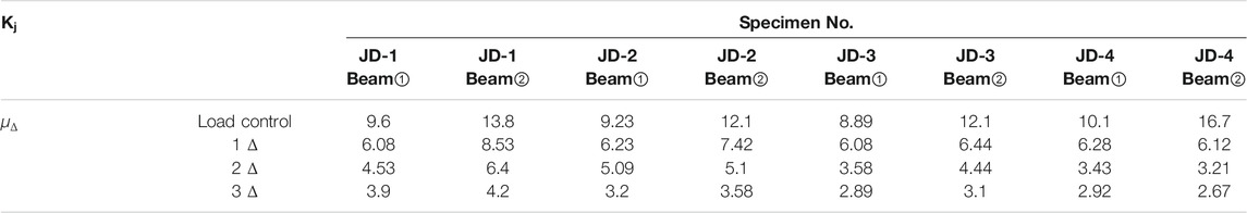
TABLE 6. Circular rigidity.
The special-shaped column structure solves the problem that the corner of the traditional frame structure affects the indoor architectural decoration due to the excessive column section, so it has been widely used in practical engineering. Reinforced concrete special-shaped column joints are usually in poor mechanical condition, and the design issues of joints are urgently explored to ensure that the new structures can be widely used. Therefore, the study of the seismic capacity of joints is necessary. In this study, low-frequency cyclic load tests were conducted on SRC special-shaped column and beam joints, which can simulate the bidirectional seismic action more accurately than common single-joint tests, and therefore the test results have a good realistic reference value. Combined with the theoretical analysis, conclusions can be obtained as follows:
1) SRC special-shaped column and reinforced concrete beam with a steel tube and structural steel inside has good anti-seismic property.
2) Stirrups at joints have positive constraining capacity on core concrete and can improve the entirety and seismic-resistant property of the structure.
3) The designing method is reliable. It can greatly improve the efficiency of construction. Anchoring of longitudinal bars in the beam is good enough to meet the anchoring requirements of seismic design, and the ductility and energy-dissipating capacities are satisfactory.
4) The joints of SRC special-shaped column and reinforced concrete beam designed in this study has small stiffness degradation, small load-bearing capacity degradation, and good ductility under bidirectional low-cyclic reversed loading.
The raw data supporting the conclusion of this article will be made available by the authors, without undue reservation.
XZ wrote the manuscript; QX finished the data analysis; BY supervised the work; WY checked figures and tables; ZD is the project leader; and PX revised and submitted the manuscript.
The work described in this paper is supported by the Systematic Project of Guangxi Key Laboratory of Disaster Prevention and Structural Safety, Project of Hubei Key Laboratory of Disaster Prevention and Mitigation, China, and Project of Engineering Research Center for Seismic Disaster Prevention and Engineering Geological Disaster Detection of Jiangxi Province.
The authors declare that the research was conducted in the absence of any commercial or financial relationships that could be construed as a potential conflict of interest.
All claims expressed in this article are solely those of the authors and do not necessarily represent those of their affiliated organizations, or those of the publisher, the editors, and the reviewers. Any product that may be evaluated in this article, or claim that may be made by its manufacturer, is not guaranteed or endorsed by the publisher.
Cao, D., Liu, J., Ge, W., and Qian, R. (2021). Experimental Study on the Shear Performance of Steel-Truss-Reinforced Concrete Beam-Column Joints. Adv. Civil Eng., 2021. doi:10.1155/2021/5580581
Chen, J., Zhao, C., Ding, F., and Xiang, P. (2019). Experimental Study on the Seismic Behavior of Precast concrete Column with Grouted Corrugated Sleeves and Debonded Longitudinal Reinforcements. Adv. Struct. Eng. 22, 3277–3289. doi:10.1177/1369433219858451
Chen, Z., and Liu, X. (2018). Seismic Behavior of Steel Reinforced concrete Cross-Shaped Column under Combined Torsion. Steel Compos. Structures 26, 407–420.
Chen, Z., Xu, D., Xu, J., and Wang, N. (2021). Seismic Behavior and Strength of L-Shaped Steel Reinforced concrete Column- concrete Beam Planar and Spatial Joints. Steel Compos. Structures 39, 337–352.
Chen, Z., Ning, F., Chen, J., Liu, X., and Xu, D. (2021). Test on Mechanical Behavior of SRC L-Shaped Columns under Combined Torsion and Bending Moment. Earthq. Eng. Eng. Vib. 20, 161–177. doi:10.1007/s11803-021-2012-0
Chen, Z., Xu, J., Chen, Y., and Xue, J. (2015). Seismic Behavior of Steel Reinforced concrete (SRC) T-Shaped Column-Beam Planar and 3D Hybrid Joints under Cyclic Loads. Earthquakes and Structures 8, 555–572. doi:10.12989/eas.2015.8.3.555
Chen, Z., Xu, J., and Xue, J. (2015). Hysteretic Behavior of Special Shaped Columns Composed of Steel and Reinforced concrete (SRC). Earthq. Eng. Eng. Vib. 14, 329–345. doi:10.1007/s11803-015-0026-1
Chu, L., Li, D., Ma, X., and Zhao, J. (2018). Cyclic Behaviour of concrete Encased Steel (CES) Column-Steel Beam Joints with concrete Slabs. Steel Compos. Structures 29, 731–744.
Chu, L., Li, Q., Zhao, J., and Li, D. (2020). Seismic Behavior of Hybrid Frame Joints between Composite Columns and Steel Beams. Shock and Vibration, 2020. doi:10.1155/2020/8870582
Chun, S. C., Lee, S. H., Kang, T. H. K., Oh, B., and Wallace, J. W. (2007). Mechanical Anchorage in Exterior Beam-Column Joints Subjected to Cyclic Loading. Aci Struct. J. 104, 102–112. doi:10.14359/18438
Deng, Z., Xu, C., Hu, Q., Zeng, J., and Xiang, P. (2018). Investigation on the Structural Behavior of Shear Walls with Steel Truss Coupling Beams under Seismic Loading. Adv. Mater. Sci. Eng. 2018. doi:10.1155/2018/5602348
Deng, Z. H., Xu, C. C., Zeng, J., Wang, H. P., Wu, X. P., and Xiang, P. Seismic Performance and Shear Bearing-Capacity of Truss SRC Beam-Column Frame Joints. Adv. Struct. Eng. 24 (7), 1311–1325. doi:10.1177/1369433220977290
Deng, Z., Hu, Q., Zeng, J., Xiang, P., and Xu, C. (2018). Structural Performance of Steel-Truss-Reinforced Composite Joints under Cyclic Loading. Proc. Inst. Civil Eng. - Structures Buildings 171, 130–148. doi:10.1680/jstbu.16.00188
Deng, Z., Xu, C., Zeng, J., Wang, H., Wu, X., and Xiang, P. (2021). Seismic Performance and Shear Bearing-Capacity of Truss SRC Beam-Column Frame Joints. Adv. Struct. Eng. 24, 1311–1325. doi:10.1177/1369433220977290
Feng, Y., Jiang, L., Zhou, W., Han, J., Zhang, Y., Nie, L., et al. (2020). Experimental Investigation on Shear Steel Bars in CRTS II Slab Ballastless Track under Low-Cyclic Reciprocating Load. Construction Building Mater., 255. doi:10.1016/j.conbuildmat.2020.119425
Huang, H., Hao, R., Zhang, W., and Huang, M. (2019). Experimental Study on Seismic Performance of Square RC Columns Subjected to Combined Loadings. Eng. Structures 184, 194–204. doi:10.1016/j.engstruct.2019.01.095
Karabinis, A. I. (2002). Reinforced concrete Beam-Column Joints with Lap Splices under Cyclic Loading. Struct. Eng. Mech. 14, 649–660. doi:10.12989/sem.2002.14.6.649
Ma, D.-Y., Han, L.-H., and Zhao, X.-L. (2019). Seismic Performance of the concrete-encased CFST Column to RC Beam Joint: Experiment. J. Constructional Steel Res. 154, 134–148. doi:10.1016/j.jcsr.2018.11.030
Metelli, G., Messali, F., Beschi, C., and Riva, P. (2015). A Model for Beam-Column Corner Joints of Existing RC Frame Subjected to Cyclic Loading. Eng. Structures 89, 79–92. doi:10.1016/j.engstruct.2015.01.038
Park, R. (2002). A Summary of Results of Simulated Seismic Load Tests on Reinforced concrete Beam-Column Joints, Beams and Columns with Substandard Reinforcing Details. J. Earthquake Eng. 6, 147–174. doi:10.1080/13632460209350413
Said, A. M. (2009). Damage Characterization of Beam-Column Joints Reinforced with GFRP under Reversed Cyclic Loading. Smart Structures Syst. 5, 443–455. doi:10.12989/sss.2009.5.4.443
Sasmal, S., Novak, B., and Ramanjaneyulu, K. (2010). Numerical Analysis of Under-designed Reinforced concrete Beam-Column Joints under Cyclic Loading. Comput. concrete 7, 203–220. doi:10.12989/cac.2010.7.3.203
Xiang, P., Deng, Z., Su, Y., Wang, H., and Wan, Y. (2017). Experimental Investigation on Joints between Steel-Reinforced concrete T-Shaped Column and Reinforced concrete Beam under Bidirectional Low-Cyclic Reversed Loading. Adv. Struct. Eng. 20, 446–460. doi:10.1177/1369433216653841
Xiang, P., Lin, Y., Huang, W., Ding, F., Ye, B., and Deng, Z. (2019). Investigation on Shear Capacity of Joints between Steel Reinforced Concrete Special-Shaped Column and Reinforced Concrete Beam. Front. Mater. 7, 588296. doi:10.3389/fmats.2020.588296
Xu, C. X., Sheng, P. S., and Wan, C. C. (2019). Experimental and Theoretical Research on Shear Strength of Seismic-Damaged SRC Frame Columns Strengthened with Enveloped Steel Jackets. Adv. Civil Eng. 2019. doi:10.1155/2019/6401730
Yu, J., Zhang, W., Tang, Z., Guo, X., and Pospisil, S. (2020). Seismic Behavior of Precast concrete Beam-Column Joints with Steel Strand Inserts under Cyclic Loading. Eng. Struct. 216, 110766. doi:10.1016/j.engstruct.2020.110766
Zhang, H., Guo, J., Wen, W., and Cui, H. (2019). Investigation on the Bending and Tensile Performances of the T-Shaped Hook-Connected Structure Made of Laminated Composites and TC4 alloy. Polym. Test. 80, 106083. doi:10.1016/j.polymertesting.2019.106083
Keywords: concrete, reinforcement, innovative, composite structures, engineering
Citation: Zhang X, Xia Q, Ye B, Yan W, Deng Z and Xiang P (2021) Seismic Performances of SRC Special-Shaped Columns and RC Beam Joints Under Double-Direction Low-Cyclic Reversed Loading. Front. Mater. 8:761376. doi: 10.3389/fmats.2021.761376
Received: 19 August 2021; Accepted: 30 September 2021;
Published: 22 November 2021.
Edited by:
Huaping Wang, Lanzhou University, ChinaReviewed by:
J. W. Yan, East China Jiaotong University, ChinaCopyright © 2021 Zhang, Xia, Ye, Yan, Deng and Xiang. This is an open-access article distributed under the terms of the Creative Commons Attribution License (CC BY). The use, distribution or reproduction in other forums is permitted, provided the original author(s) and the copyright owner(s) are credited and that the original publication in this journal is cited, in accordance with accepted academic practice. No use, distribution or reproduction is permitted which does not comply with these terms.
*Correspondence: Ping Xiang, cHhpYW5nMi1jQG15LmNpdHl1LmVkdS5oaw==
Disclaimer: All claims expressed in this article are solely those of the authors and do not necessarily represent those of their affiliated organizations, or those of the publisher, the editors and the reviewers. Any product that may be evaluated in this article or claim that may be made by its manufacturer is not guaranteed or endorsed by the publisher.
Research integrity at Frontiers
Learn more about the work of our research integrity team to safeguard the quality of each article we publish.