
94% of researchers rate our articles as excellent or good
Learn more about the work of our research integrity team to safeguard the quality of each article we publish.
Find out more
ORIGINAL RESEARCH article
Front. Mater., 14 September 2021
Sec. Structural Materials
Volume 8 - 2021 | https://doi.org/10.3389/fmats.2021.761088
This article is part of the Research TopicJoining and Welding of New and Dissimilar MaterialsView all 7 articles
 Hongliang Li1
 Zeyu Wang1,2*
 Hassaan Ahmad Butt3
 Maocheng Ye1Hao Chen1Tianmo Zhao1Manni Li4Qiang Ma5Yucheng Lei1
Cu foam has previously been investigated and verified to be an excellent interlayer candidate for relieving high residual stress within C/C composite-Nb brazed joints. However, the optimized geometric structure of Cu foam for brazing has never been properly investigated since it was always employed as a reactant for acquiring homogeneous distribution of the interfacial structures in the brazed joints. In this work, graphene reinforced Cu foam composite (G-Cuf) interlayers were used for brazing C/C composite and Nb. Through the protection effect of graphene on the Cu foam substrate, the impact of porosity and thickness of a structurally intact Cu foam on the joint structure and properties were investigated by finite elemental analysis as well as through experimental studies. By introducing a G-Cuf interlayer with an optimized porosity of 90% and thickness of 0.15 mm, the shear strength of the C/C composite-Nb brazed joint reached 45 MPa, which is 3.5 times higher than that of the joint brazed directly without an interlayer. The strain energy of the brazed joint assisted by G-Cuf interlayer reduced from as high as 10.98 × 10⁻⁶ J to 6.90 × 10⁻⁶ J, suggesting that the residual stress was effectively mitigated.
With the rapid growth of the aerospace industry, carbon fiber reinforced carbon composite materials (C/C) have been considered as one of the most promising candidates for fabricating rocket nozzles as part of combustion chambers due to their excellent high-temperature properties, low density, as well as low coefficient of thermal expansion (CTE) (Krishnarao et al., 2018; Yang et al., 2019; Ba et al., 2020b; He et al., 2020). Meanwhile, metallic niobium (Nb) has been widely used for manufacturing throat rings, which are always required to be joined with the rocket nozzle (Ba et al., 2020a; Chen et al., 2020). Among various joining technologies, vacuum brazing is the most suitable for connecting metal/alloy and ceramic/composite due to its distinct characteristics of convenience and efficiency, particularly for joining C/C and Nb (Luo et al., 2018; Jin et al., 2020; Niu et al., 2020). Nevertheless, the high CTE difference between C/C (∼2.0 × 10⁻⁶ K−1) and Nb (∼7.2 × 10⁻⁶ K−1) has been generating an unavoidable intrinsic issue of high residual stress in the brazed joint, which deteriorates the joint properties severely.
To address this issue, a variety of reinforcement materials have been introduced into such joints to optimize the seam microstructures and to improve the CTE mismatch between the parent materials (Yang et al., 2019; Ba et al., 2020b; Ong et al., 2021; Yi et al., 2021). Research in the past decade has manifested in the form of metallic foams, such as Cu (Wang et al., 2018, 2019; Guo et al., 2020), Ni (Ba et al., 2018; Guo et al., 2019) and stainless-steel (Shirzadi et al., 2008), to name a few. These have become “hot topic” materials for use as brazing interlayers, which have contributed to significant improvement of brazed joint properties. In these investigations, the purpose of using metallic foams during the brazing process could generally be summarized as follows: 1) By taking the advantage of its high specific area, a metallic foam could serve as growth substrate for carrying another reinforcement material into the seam massively and homogeneously. 2) With the help the of the unique three-dimensional skeleton and good chemical activity of the metallic foam, in-situ formed reinforcement materials could be evenly distributed in the seam. 3) Through the exploitation of the intrinsic ductile property of the metallic foam, the residual stress could be released. In brief, the approach of employing metallic foams indeed contributes towards improving the joint strength effectively, whereas peculiar metallic foams are almost always required to be sacrificed by reacting with the brazing filler for producing in-situ reinforcements. This method generally gives rise to great difficulty in studying the impact of a structurally intact metallic foam on the residual stress mitigation behavior, which needs to be inherently characterized to ascertain the effect it has on the final system. It is worth noting that the unique strain accommodation capability of a metallic foam, reported by Gibson and Ashby (Andrews et al., 1999), can play a crucial part in reliving the residual stress, which was always been neglected when applying the metallic foam as a reactant. In short, it is apparently essential to study the role of a structurally intact metallic foam and its action in residual stress relief during the brazing process. To overcome this issue, our previous work reported a three-dimensional graphene coated Cu foam composite (G-Cuf) interlayer fabricated via the chemical vapor deposition method, which led to an exciting increase in the shear strength of the C/C composite-Nb brazed joint (Wang et al., 2017). Owing to the excellent chemical inertness of graphene, the Cu foam skeleton substrate was protected from being chemically etched by the Ag-Cu-Ti brazing filler at high temperature. Thus, there is no doubt that the G-Cuf interlayer is an ideal candidate for investigating the role of ductile network-structural materials in relieving the residual stress and enhancing the joint strength in brazed joints.
In the current study, our previous work is furthered by focusing on the impact of the geometric structure of the G-Cuf interlayer on the joint strength and the residual stress relief mechanism. Through simulating the residual stress of the joint by using finite element analysis (FEA), the geometric parameter of the G-Cuf interlayer are optimized. Afterwards, experimental study is conducted for verification of the simulative portion. Ultimately, the residual stress reliving mechanism of the joint, exerted by the G-Cuf interlayer, is also discussed in terms of the strain energy theory. This work is expected to point towards a perspective on the role of structurally intact metallic foams as brazing interlayers and on their ability of mitigating brazed joint residual stress.
Initially, the G-Cuf interlayer was fabricated via chemical vapor deposition at 1,000°C using methane (CH4) gas as a precursor under a mixed atmosphere of hydrogen and argon gas. The preparation details of this experimentation may be found in detail in our previous work (Wang et al., 2017). Post process, a combination of Ag-Cu-Ti foil/G-Cuf interlayer/Ag-Cu-Ti foil was sandwiched between C/C and Nb parent materials, the schematic of which is shown in Figure 1. The joining surfaces of C/C and Nb were ground by SiC grit paper and ultrasonically cleaned in alcohol and acetone prior to the brazing process. Next, the brazing assembly, pressured by a graphite jig for better contact, was heated to 880°C at the rate of 10°C/min, then held at 880°C for 10 min, followed by being cooled to room temperature at the rate of 5°C/min in a vacuum furnace. The microstructures of the joint interfaces were examined through a scanning electron microscope (SEM) equipment. The shear strength of the brazed joint was evaluated using the Instron 1,186 machine at room temperature with a strain rate of 0.2 mm·min−1.
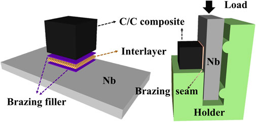
FIGURE 1. Schematic of the brazing assembly (left) and shear strength test assembly (right).
FEA was conducted by applying COMSOL Multiphysics software to study the residual stress distribution within the joints. The geometric model of the joint includes the following three parts: C/C composite, brazing seam composite (BSC) and Nb, all of which use graded free-triangle mesh, as shown in Supplementary Figure S1. The joint is cooled down from 820 to 20°C at the rate of 5°C·min−1 during the simulation. It should be clarified here that the Ag-Cu-Ti brazing filler keeps a solid state throughout the FEA simulation, with no change in phase taking place. Thus, the BSC is designed to be a laminar-shaped slice which is composed of the intact G-Cuf interlayer and Ag-Cu-Ti brazing filler filled within the porous inner space of the G-Cuf interlayer. Note that neither pore density (PPI) nor morphology, but only the porosity is mentioned since PPI and morphology have negligible effects on the overall physical and mechanical properties of the G-Cuf interlayer (Gibson and Ashby, 1982; Andrews et al., 1999). The thickness of the BSC was also considered during the simulation since it is deemed a crucial factor effecting the joint strength (Erskine et al., 2014; de Prado et al., 2020). In this work, the porosity and thickness of the G-Cuf interlayers vary in the range of 60–98% and 0.05–0.3 mm, respectively.
Due to the advantages of high degree of resemblance in structure, close-packed pore units as well as distinct structural periodicity, the truncated octahedron (Kelvin) model was applied to build the G-Cuf interlayer skeleton for FEA calculation, as depicted in Figure 2. In each minimized unit (marked as a rectangular with red dash line), ligaments and nodes of the G-Cuf interlayer skeleton are corresponding to the green line segments and endpoints, respectively. The unoccupied space (white part) in the same unit corresponds to the Ag-Cu-Ti brazing filler, which filled the pores within the G-Cuf interlayer well. According to Kanaun and Jaeger’s studies (Kanaun and Tkachenko, 2008; De Jaeger et al., 2011), it could be calculated that the porosity of the Kelvin model is in the range of 60–100%, which shows almost no difference compared with a common commercial open-cell Cu foam. On this basis, the porosity (φm) of the G-Cuf interlayers studied in the current work are 60, 75, 90 and 98%.
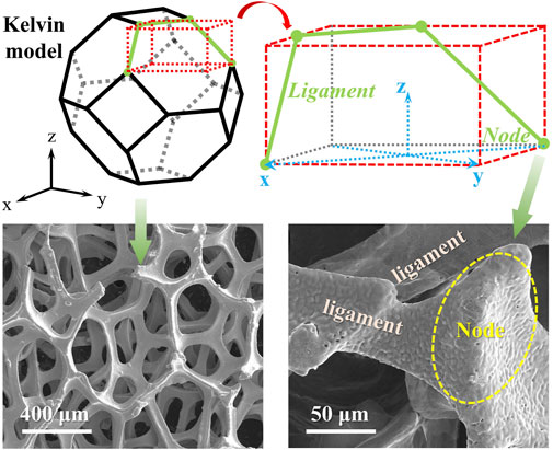
FIGURE 2. Schematic of Kelvin model and its structural correspondence to the G-Cuf skeleton.
To acquire the physical and mechanical properties of the BSC, a modified Mori-Tanka model reported by Wakashima (Wakashima and Tsukamoto, 1991) is employed to calculate the modulus of elasticity, bulk modulus, shear elasticity and the Poisson’s ratio of the BSC. The Kerner model (Balch et al., 1996) and shear-lag model (Weerasinghe et al., 2017; Hu et al., 2019) are utilized to obtain the CTE and yield strength of the BSC, respectively. Note that the coefficient of the Hashin bulk modulus required for calculating the CTE of BSC could be acquired from the modified Mori-Tanka model (Wakashima and Tsukamoto, 1991). Additionally, it is worth mentioning that the prepared graphene has negligible impact on the physical and mechanical properties of Cu foam substrate since the thickness of graphene is extremely thin, even if its intrinsic properties are much better than Cu. The specific physical and mechanical properties of C/C composite, Nb and different BSCs derived from the G-Cuf interlayer with different porosities are presented in Supplementary Tables S1–S3 in the supplementary material.
At first, the shear residual stress τx and the axial residual stress σz distribution in C/C-Nb joints brazed using G-Cuf interlayers with the same thickness (h = 0.2 mm) and different porosities were evaluated, with the results presented in Figure 3.
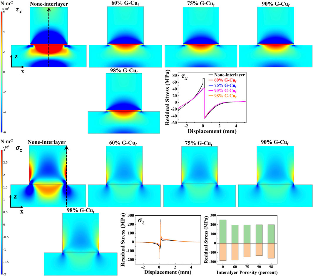
FIGURE 3. τx and σz distribution in C/C-Nb joints brazed with different G-Cuf interlayers differing in porosity.
It is worth noting that the peak value of τx is always located at the center of the brazing seam, whereas the peak value of σz is always located at the edge of the brazing seam. This may be attributed to high tensile stress in the opposite direction, derived from dramatic CTE difference between C/C composite and Nb parent materials. In this section, note that the positive and negative values of τx and σz merely differ in the stress direction. On one hand, it is obvious that τx in the joint brazed directly without an interlayer reached its maximum value around 73 MPa/−50 MPa at the interface in-between C/C composite and the brazing seam and then gradually diminished as the studied position moved away from the interface. By contrast, the peak value of τx in the C/C composite-Nb joints brazed with a G-Cuf interlayer distinctly decreased to approximately 43 MPa/−47 MPa. This change suggests that the introduction of the G-Cuf interlayer contributed significantly to reducing τx, while the variation of porosity of the G-Cuf interlayer did not significantly affect the distribution of τx. On the other hand, the peak value of σz of the joint brazed directly without an interlayer reached −186 MPa/252 MPa. When introducing G-Cuf interlayers, the peak value of σz in-between C/C and the brazing seam dropped to around 200 MPa, but the peak value of σz in-between Nb and the brazing seam almost unchanged. Although the interface between the brazing seam and Nb is not supposed to be weakest area in the system, the peak value of σz of the G-Cuf interlayer with 90% porosity reduced to the minimum value (−133 MPa/200 MPa).
τx and σz distribution in C/C-Nb joints brazed using G-Cuf interlayers with the same porosity (φm = 90%) and different thickness were also calculated, as depicted in Figure 4. It is distinct that the thickness of G-Cuf interlayer had neglectable impact on the τx in-between Nb and the brazing seam, while σz decreased from −61 MPa to −41 MPa as the thickness increased from 0.05 to 0.3 mm. However, σz of the joints brazed using G-Cuf interlayers with different thicknesses evidently altered. Specifically, σz of the joints at the interface between the brazing seam and parent materials were −178 MPa/194 MPa, −105 MPa/173 MPa, −95 MPa/173 MPa, −133 MPa/223 MPa as well as −199 MPa/255 MPa, corresponding to G-Cuf interlayer thicknesses of 0.05, 0.1, 0.15, 0.2 and 0.3 mm respectively. To summarize, the G-Cuf interlayer with a thickness of 0.15 mm and a porosity of 90% displayed optimum properties.
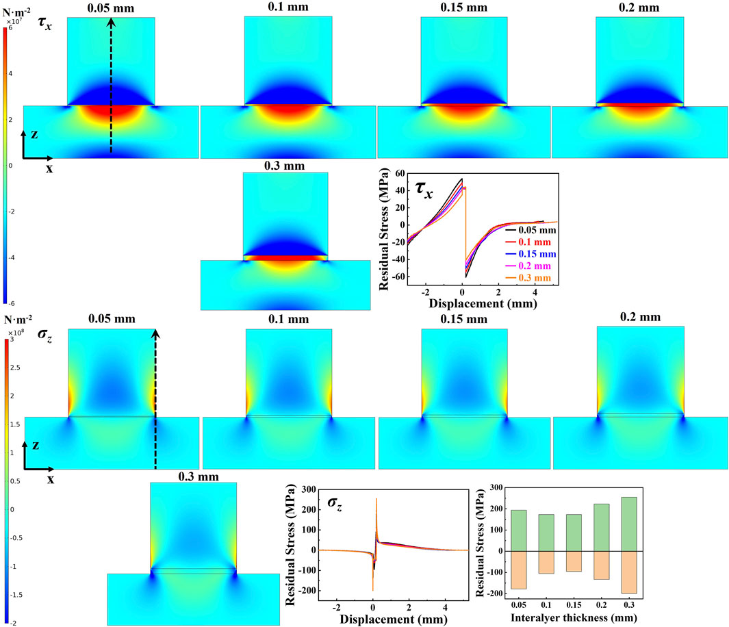
FIGURE 4. τx and σz distribution in C/C-Nb joints brazed with different G-Cuf interlayers differing in thickness.
In order to verify the computational data acquired by FEA simulation, C/C composite and Nb were experimentally brazed by using different G-Cuf interlayers. The interfacial microstructures and shear strength at room temperature of the joints brazed by using G-Cuf interlayers differing in porosity (h = 0.2 mm) are shown in Figure 5.
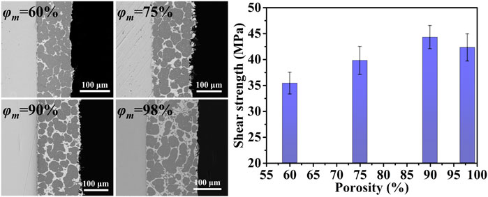
FIGURE 5. SEM images and mechanical performance of C/C-Nb joints brazed using different G-Cuf interlayers differing in thickness.
The uniformly distributed dark grey phases correspond to the Cu solid solution derived mainly from the Cu foam substrate and the light grey phases correspond to Ag solid solution derived from the Ag-Cu-Ti brazing filler (Wang et al., 2017). When applying a G-Cuf interlayer (φm = 60%), the network skeleton occupied the main part within the brazing seam which makes the Cu foam substrate easier to soft during brazing process at high temperature. At the same time, a relatively low porosity gave rise to higher friction forces and a larger Renault coefficient, which may cause deterioration of the brazing filler flow through the pores within the G-Cuf interlayer. The shear strength at room temperature of the corresponding joint was 35 MPa. As φm increases to 75%, the distribution of Cu solid solution was improved to some extent and the shear strength of the joint rose to 39 MPa. When φm increases to 90%, the G-Cuf interlayer skeleton remained intact to exert its synergetic function and the joint shear strength reached 44 MPa. However, as the φm increased up to 98%, the joint shear strength slightly decreased to 42 MPa. This could be attributed to the deterioration of the strain accommodation capacity of G-Cuf interlayer which consequently influenced the joint residual stress mitigation (Gibson and Ashby, 1982; Andrews et al., 1999). The above experimental results suggest that the joint brazed with a G-Cuf interlayer with a porosity of 90% (h = 0.2 mm) performed the best with the highest shear strength. This is consistent with the FEA simulation prediction conducted during this study.
Based on the results above, the thickness of G-Cuf interlayer has been further optimized. The interfacial microstructures and shear strengths at room temperature of the joints brazed by using G-Cuf interlayers differing in thickness (φm = 90%) are shown in Figure 6. When h was as low as 0.05 mm, the G-Cuf interlayer is extremely weak and it is difficult to maintain its network structure during the brazing process, resulting in the joint shear strength being merely 33 MPa. As h increased to 0.1 mm, the network structure of the G-Cuf interlayer was retained and the joint shear strength increased to 37 MPa. When h increased to 0.15 mm, the network skeleton was still retained but the joint shear strength stabilized at a value of 45 MPa. For the joints brazed by employing a G-Cuf interlayer with h ≥ 0.2 mm, the network skeleton of the G-Cuf interlayer was retained but the joint shear strength also remained stable at a value of 44 MPa. The results above imply that when φm = 90% and h = 0.15 mm, the geometric parameter of the G-Cuf interlayer are optimum and the shear strength of the corresponding joint is ∼3.5 times that of the joint brazed directly without interlayer (13 MPa) (Wang et al., 2017).
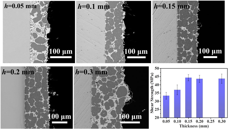
FIGURE 6. SEM images and mechanical performance of C/C-Nb joints brazed using different G-Cuf interlayers differing in thickness.
Ultimately, the mechanism of residual stress relief of the joint by applying the G-Cuf interlayer is evaluated by strain energy theory (Park et al., 2002). Specifically, the strain energy Ue,C is associated with the equivalent yield strength σseam, the joint contact parameter r, as well as a correction function f (A, B):
The correction function f (A, B) in Eq. 1 could be further expressed as follows:
Herein, A and B in Eq. 2 are associated with the coefficient of thermal expansion of the parent materials αNb and αC/C, the temperature difference ΔT, the equivalent elastic modulus and the coefficient of thermal expansion of the brazing seam Eseam and αseam, respectively. The formulae are expressed as follows:
By introducing the required data exhibited in the supplementary material, A and B factors in Eqs 3, 4, are calculated to be 3.22 and 0.36, respectively. Thus, the value of f (A, B) is around 0.618 and the Ue,C is consequently 6.90 × 10⁻⁶ J, for the brazed joint assisted by the G-Cuf interlayer. By comparison, the joint brazed directly without an interlayer shows a Ue,C value as high as 10.98 × 10⁻⁶ J. The experimental and theoretical results make it clear that the introduction of G-Cuf interlayers contributed remarkably to reducing the strain energy. In other words, the G-Cuf interlayer effectively enhanced the joint plasticity and toughness which is conducive to relieving the joint residual stress and hence the joint shear strength increased significantly.
In summary, by using a G-Cuf interlayer for brazing, the structure of the Cu foam substrate remained intact during the brazing process. On this basis, the porosity and thickness of the Cu foam substrate was optimized to be 90% and 0.15 mm, respectively. The shear strength of the corresponding joint reached 45 MPa which is ∼3.5 times that of the joint brazed directly without an interlayer. By introducing the optimized interlayer, the strain energy of the joint reduced significantly from as high as 10.98 × 10⁻⁶ J to 6.90 × 10⁻⁶ J, implying that this optimized interlayer played a key role in relieving the residual stress.
The raw data supporting the conclusions of this article will be made available by the authors, without undue reservation.
HL and ZW conducted all experimental investigation and theoretical analysis in the current study and wrote the manuscript. HB polished the language. MY, HC, TZ as well as ZW carried out the FEA simulation calculation. ML and QM conducted deep review and editing. YL contributed the guidance and supervision. All authors have read and approved the article for publication.
The support from the National Natural Science Foundation of China (Grant Nos 51575135 and 51622503) is highly appreciated.
The authors declare that the research was conducted in the absence of any commercial or financial relationships that could be construed as a potential conflict of interest.
All claims expressed in this article are solely those of the authors and do not necessarily represent those of their affiliated organizations, or those of the publisher, the editors and the reviewers. Any product that may be evaluated in this article, or claim that may be made by its manufacturer, is not guaranteed or endorsed by the publisher.
The Supplementary Material for this article can be found online at: https://www.frontiersin.org/articles/10.3389/fmats.2021.761088/full#supplementary-material
Andrews, E. W., Gibson, L. J., and Ashby, M. F. (1999). The Creep of Cellular Solids. Acta Mater. 47, 2853–2863. doi:10.1016/S1359-6454(99)00150-0
Ba, J., Lin, J., Wang, H., Qi, B., Zhong, Z., Wang, Z., et al. (2018). Carbon Nanotubes-Reinforced Ni Foam Interlayer for Brazing SiO2-BN with Ti6Al4V alloy Using TiZrNiCu Brazing Alloy. Ceram. Int. 44, 3684–3691. doi:10.1016/j.ceramint.2017.11.136
Ba, J., Ji, X., Li, H., Lin, J., Qi, J., and Cao, J. (2020a). Nano Tungsten Reinforced Carbon Cloth Interlayer for Brazing C/SiC Composites to Nb. J. Manuf. Process. 58, 1270–1273. doi:10.1016/j.jmapro.2020.09.033
Ba, J., Wang, B., Ji, X., Li, H., Lin, J., Zheng, X., et al. (2020b). β-LiAlSiO4 Negative Thermal Expansion Network Interlayer for C/C-Nb Brazing Joint. Ceram. Int. 46, 14232–14234. doi:10.1016/j.ceramint.2020.01.283
Balch, D. K., Mortensen, A., Suresh, S., Shen, Y.-L., Fitzgerald, T. J., and Michaud, V. J. (1996). Thermal Expansion of Metals Reinforced with Ceramic Particles and Microcellular Foams. Mmta 27, 3700–3717. doi:10.1007/BF02595462
Chen, B., Zou, W.-J., Li, W.-W., Wu, S.-B., Xiong, H.-P., and Wu, X. (2020). Joining of SiO2f/SiO2 Composite to Nb Using Ag-Cu-In-Ti Brazing Alloys. J. Mater. Sci. Technol. 50, 13–20. doi:10.1016/j.jmst.2019.08.002
De Jaeger, P., T’Joen, C., Huisseune, H., Ameel, B., and De Paepe, M. (2011). An Experimentally Validated and Parameterized Periodic Unit-Cell Reconstruction of Open-Cell Foams. J. Appl. Phys. 109, 103519. doi:10.1063/1.3587159
de Prado, J., Sánchez, M., Ruiz, A., and Ureña, A. (2020). Effect of Brazing Temperature, Filler Thickness and post Brazing Heat Treatment on the Microstructure and Mechanical Properties of W-Eurofer Joints Brazed with Cu Interlayers. J. Nucl. Mater. 533, 152117. doi:10.1016/j.jnucmat.2020.152117
Erskine, K. M., Meier, A. M., Joshi, V. V., and Pilgrim, S. M. (2014). The Effect of Braze Interlayer Thickness on the Mechanical Strength of Alumina Brazed with Ag-CuO Braze Alloys. Adv. Eng. Mater. 16, 1442–1447. doi:10.1002/adem.201400128
Gibson, L. J., and Ashby, M. F. (1982). The Mechanics of Three-Dimensional Cellular Materials. Proc. R. Soc. Lond. A. 382, 43–59. doi:10.1098/rspa.1982.0088
Guo, W., Zhang, H., Ma, K., Zhu, Y., Zhang, H., Qi, B., et al. (2019). Reactive Brazing of Silicon Nitride to Invar alloy Using Ni Foam and AgCuTi Intermediate Layers. Ceram. Int. 45, 13979–13987. doi:10.1016/j.ceramint.2019.04.097
Guo, W., Xue, J., Zhang, H., Cui, H., Zhu, Y., Peng, P., et al. (2020). The Role of Foam on Microstructure and Strength of the Brazed C/C composites/Ti6Al4V alloy Joint. Vacuum 179, 109543. doi:10.1016/j.vacuum.2020.109543
He, Z., Sun, L., Li, C., Si, X., Zhang, C., Qi, J., et al. (2020). Wetting and Brazing of Cf/C Composites with Si-Zr Eutectic Alloys: The Formation of Nano- and Coarse-SiC Reaction Layers. Carbon 167, 92–103. doi:10.1016/j.carbon.2020.05.109
Hu, Y.-G., Li, Y. F., Han, J., Hu, C. P., Chen, Z. h., and Gu, S. T. (2019). Prediction of Interface Stiffness of Single-Walled Carbon Nanotube-Reinforced Polymer Composites by Shear-Lag Model. Acta Mech. 230, 2771–2782. doi:10.1007/s00707-019-02426-7
Jin, C., Wang, Y., Yang, Z., and Wang, D. (2020). C/C Composite Surface Modified by Electrophoretic Depositing SiC Nanowires and its Brazing to Nb. Ceram. Int. 46, 204–211. doi:10.1016/j.ceramint.2019.08.249
Kanaun, S., and Tkachenko, O. (2008). Effective Conductive Properties of Open-Cell Foams. Int. J. Eng. Sci. 46, 551–571. doi:10.1016/j.ijengsci.2008.01.012
Krishnarao, R. V., Alam, M. Z., and Das, D. K. (2018). In-Ssitu Formation of SiC, ZrB2-SiC and ZrB2-SiC-B4C-YAG Coatings for High Temperature Oxidation Protection of C/C Composites. Corros. Sci. 141, 72–80. doi:10.1016/j.corsci.2018.07.002
Luo, Y., Bian, H., Niu, H. W., Song, Y. Y., Chen, Z. B., Song, X. G., et al. (2018). Interfacial Microstructure and Mechanical Properties of C/C Composites and Nb Joints Brazed with Cu75Pt25 Filler Metal. Vacuum 157, 202–209. doi:10.1016/j.vacuum.2018.08.036
Niu, S., Yang, Z., Wang, C., Han, Y., Wang, Y., and Wang, D. (2020). Improving the Bonding Strength of Nb-C/C Composite Brazed Structures by Preoxidation. Adv. Eng. Mater. 22, 2000065. doi:10.1002/adem.202000065
Ong, F. S., Rheingans, B., Goto, K., Tobe, H., Ohmura, T., Janczak-Rusch, J., et al. (2021). Residual Stress Induced Failure of Ti-6Al-4V/Si3N4 Joints Brazed with Ag-Cu-Ti Filler: The Effects of Brazing Zone's Elasto-Plasticity and Ceramics' Intrinsic Properties. J. Eur. Ceram. Soc. 41, 6319–6329. doi:10.1016/j.jeurceramsoc.2021.06.038
Park, J.-W., Mendez, P. F., and Eagar, T. W. (2002). Strain Energy Distribution in Ceramic-To-Metal Joints. Acta Mater. 50, 883–899. doi:10.1016/S1359-6454(01)00352-4
Shirzadi, A. A., Zhu, Y., and Bhadeshia, H. K. D. H. (2008). Joining Ceramics to Metals Using Metallic Foam. Mater. Sci. Eng. A 496, 501–506. doi:10.1016/j.msea.2008.06.007
Wakashima, K., and Tsukamoto, H. (1991). Mean-field Micromechanics Model and its Application to the Analysis of Thermomechanical Behaviour of Composite Materials. Mater. Sci. Eng. A 146, 291–316. doi:10.1016/0921-5093(91)90284-T
Wang, Z., Wang, G., Li, M., Lin, J., Ma, Q., Zhang, A., et al. (2017). Three-Dimensional Graphene-Reinforced Cu Foam Interlayer for Brazing C/C Composites and Nb. Carbon 118, 723–730. doi:10.1016/j.carbon.2017.03.099
Wang, X., Li, C., Si, X., Qi, J., Feng, J., and Cao, J. (2018). Brazing ZTA Ceramic to TC4 Alloy Using the Cu Foam as Interlayer. Vacuum 155, 7–15. doi:10.1016/j.vacuum.2018.05.038
Wang, G., Cai, Y., Wang, W., Gui, K., Zhu, D., Tan, C., et al. (2019). Brazing ZrB2-SiC Ceramics to Inconel 600 alloy without and with Cu Foam. J. Manuf. Process. 41, 29–35. doi:10.1016/j.jmapro.2019.03.023
Weerasinghe, A., Lu, C.-T., Maroudas, D., and Ramasubramaniam, A. (2017). Multiscale Shear-Lag Analysis of Stiffness Enhancement in Polymer-Graphene Nanocomposites. ACS Appl. Mater. Inter. 9, 23092–23098. doi:10.1021/acsami.7b03159
Yang, Z. W., Wang, C. L., Han, Y., Zhao, Y. T., Wang, Y., and Wang, D. P. (2019). Design of Reinforced Interfacial Structure in Brazed Joints of C/C Composites and Nb by Pre-oxidation Surface Treatment Combined with In Situ Growth of CNTs. Carbon 143, 494–506. doi:10.1016/j.carbon.2018.11.047
Keywords: Cu foam, interlayer, residual stress, C/C composite, brazing, structurally intact, finite elemental analysis
Citation: Li H, Wang Z, Butt HA, Ye M, Chen H, Zhao T, Li M, Ma Q and Lei Y (2021) Study on the Residual Stress Relieving Mechanism of C/C Composite-Nb Brazed Joint by Employing a Structurally Optimized Graphene Reinforced Cu Foam Interlayer. Front. Mater. 8:761088. doi: 10.3389/fmats.2021.761088
Received: 19 August 2021; Accepted: 02 September 2021;
Published: 14 September 2021.
Edited by:
Xiangchen Meng, Harbin Institute of Technology, ChinaReviewed by:
Junlei Qi, Harbin Institute of Technology, ChinaCopyright © 2021 Li, Wang, Butt, Ye, Chen, Zhao, Li, Ma and Lei. This is an open-access article distributed under the terms of the Creative Commons Attribution License (CC BY). The use, distribution or reproduction in other forums is permitted, provided the original author(s) and the copyright owner(s) are credited and that the original publication in this journal is cited, in accordance with accepted academic practice. No use, distribution or reproduction is permitted which does not comply with these terms.
*Correspondence: Zeyu Wang, enl3YW5nQHVqcy5lZHUuY24=
Disclaimer: All claims expressed in this article are solely those of the authors and do not necessarily represent those of their affiliated organizations, or those of the publisher, the editors and the reviewers. Any product that may be evaluated in this article or claim that may be made by its manufacturer is not guaranteed or endorsed by the publisher.
Research integrity at Frontiers
Learn more about the work of our research integrity team to safeguard the quality of each article we publish.