 Bingbing Guo1,2,3*
 Zhenming Li
95% of researchers rate our articles as excellent or good
Learn more about the work of our research integrity team to safeguard the quality of each article we publish.
Find out more
ORIGINAL RESEARCH article
Front. Mater. , 12 October 2021
Sec. Structural Materials
Volume 8 - 2021 | https://doi.org/10.3389/fmats.2021.755241
This article is part of the Research Topic 2021 Retrospective: Structural Materials View all 13 articles
Utilizing coral aggregate concrete (CAC) for construction on remote islands can significantly reduce construction cost and period, CO2 emission, and consumption of non-renewable energy. The durability of reinforced CAC structures is critically influenced by their resistance to chloride attack. In this study, a reactive transport modelling was developed to investigate chloride ingress in CAC, in which a COMSOL-PHREEQC interface based on MATLAB language was established. The experiment from the literature was taken as a benchmark example. The results show that the developed numerical model can accurately predict chloride transport in CAC. Differing from ordinary aggregate concrete (OAC), Kuzel’s salt does not appear in cement hydrate compounds of CAC during chloride ingress. The numerical results indicate that the penetration depth of chloride in CAC gradually increases as the exposure time is prolonged. When CAC is exposed to an external chloride solution, the decrease in the pH of the pore solution affects the precipitation of Friedel’s salt, which is detrimental to the chemical binding of chloride.
In recent decades, increasing number of islands and reefs, which are generally far from the mainland, have been constructed to meet the needs of rapidly developing of marine industry. Concrete is a primary building material for island and reef construction. Enormous amounts of raw materials, such as river sand, gravel, and freshwater, need to be shipped to produce concrete. This is associated with high cost, long period, CO2 emission, and the consumption of non-renewable energy (Zhou et al., 2021). A sustainable solution is to use locally available materials to produce concrete, such as seawater, sea sand, and coral reefs (Gui et al., 2020; Liu et al., 2020; Wu et al., 2020). There are abundant coral sources in remote islands and reefs, and using crushed coral as coarse and fine aggregates to produce concrete has been proven feasible (Da et al., 2016; Liang et al., 2021, Liang et al., 2021a).
The corrosion of reinforcing steel caused by chloride ingress is the primary threat to the durability of reinforced concrete (RC) structures located in marine environments (Angst et al., 2009; Li et al., 2014; Hou et al., 2017). Through field surveys, Yu et al. (2017) found that the corrosion rates of reinforcing steel embedded in concrete in tropical islands and reefs were very high, which led to cracking, spalling, and collapse of the concrete cover. Coral reefs contain chloride salt (Yu et al., 2020). When coral reefs are used as coarse or fine aggregates, the chloride salt will inevitably be mixed into concrete (Da et al., 2016; Huang et al., 2020a; Zhang et al., 2020). Hence, corrosion of reinforcing steel embedded in coral aggregate concrete (CAC) is supposed to be more serious than that of ordinary aggregate concrete (OAC). It is commonly accepted that the initiation of steel corrosion depends on the ratio of [Cl−]/[OH−] in the pore solution near the reinforcing steel. When the [Cl−]/[OH−] ratio exceeds the threshold value, the passive layer at the steel surface is destroyed, and the corrosion will occur. Therefore, the transport behaviour of chloride in CAC is closely related to the durability of CAC and the service life of CAC structures.
In addition to the fact that coral aggregates contain chloride salt, coral reefs are a type of porous and light rock, which differs completely from ordinary aggregates. These two features make CAC more vulnerable to chloride attack than OAC (Wattanachai et al., 2009). The experimental results in (Yu et al., 2017) indicated that the free chloride concentration is much higher in OAC than CAC when exposed to the same chloride environment. Da et al. (2016) and Huang et al. (2020a) found that the surface chloride concentration in CAC and its apparent chloride diffusion coefficient were higher than those of OAC.
Numerical modelling of ionic transport can predict the spatial-temporal distributions of chloride and pH in the pore solution of concrete, providing a theoretical basis for the durability design of CAC and the service life prediction of structures. Thus, in addition to experimental investigations, numerical modelling is also a powerful tool for studying chloride ingress in cement-based materials (Lehner et al., 2021). However, to our best knowledge, no studies related to the numerical modelling of chloride transport in CAC have been reported.
Numerical models based on the Nernst-Planck equations are widely used to simulate the ionic transport in concrete materials (Baroghel-Bouny et al., 2011; Liu et al., 2015; Yuan et al., 2011). The chloride binding behaviour has a significant effect on ionic transport in concrete materials. Binding isotherms, i.e., linear, Langmuir, Freundlich, and BET binding isotherms, are widely used to describe chloride binding behaviours in the numerical models from Baroghel−Bouny et al. (2011), Liu et al. (2015), and Yuan et al. (2011). However, there are two problems when using the binding isotherms: 1) none of these can accurately describe this relationship between free and bound chlorides with the global free chloride concentration range (Yuan et al., 2009); 2) the parameters in these isotherms need to be fitted from the experimental data, while each concrete material has specific parameters (Tran et al., 2018). Chloride binding in cement-based materials is dependent on the physical and chemical interactions between the cement hydrate and pore solution (Elakneswaran et al., 2010; Guo et al., 2018). Reactive transport modelling coupled with physical and chemical interactions can resolve the above-mentioned problems. Recently, reactive transport modelling of chloride ingress in cement-based materials has attracted great attention from researchers (Kari et al., 2013; Guo et al., 2018; Van Quan et al., 2018; Angst, 2019; Guo et al., 2021). In this study, reactive transport modelling was developed to simulate chloride ingress for saturated CAC.
Chloride in CAC exists in two forms: free chloride in the pore solution and bound chloride by cement hydrate. When external chloride penetrates CAC, it will cause physical and chemical interactions between the pore solution and cement hydrate, and the amount of chloride bound by the cement hydrate will increase (Huang et al., 2020a), significantly affecting the ionic transport in CAC. The physical and chemical interactions include the adsorption between the surface silanol sites (≡SiOH) of calcium silicate hydrate (C−S−H) and the aqueous species in the pore solution, and the dissolution/precipitation reactions of hydrate phases (Elakneswaran et al., 2010; Tran et al., 2018). The adsorption and dissolution/precipitation reactions can be described using the surface complexation model (Elakneswaran et al., 2009) and the phase-equilibrium model (Elakneswaran et al., 2010), respectively.
According to (Elakneswaran et al., 2008; 2009) and (Guo et al., 2018), in cement-based materials, the aqueous species in the pore solution that participates in the adsorption reactions of the C−S−H surface are mainly Na+, K+, Ca2+, OH−, and Cl−, and other species can be neglected. The surface charge density is calculated using the following equation:
where σ is the surface charge density (C/m2); F is the Faraday constant (96,485 C/mol); ΓH, ΓOH, ΓCl, ΓCa, ΓNa, and ΓK denote the densities (mol/m2) of bound protons, hydroxyl, chloride, calcium, sodium, and potassium, respectively. Based on the Gouy-Chapman diffuse theory, σ is related to the surface potential (ψ0) for a symmetrical electrolyte with valence z:
where c denotes the electrolyte concentration (mol/L). Combining Eqs 1, 2, we obtain:
The mass action law is used to describe the surface site reactions in the equilibrium state:
where Ki is the equilibrium constant of the surface site reaction of C−S−H with the ion i in the pore solution, and the surface site reactions, as presented in Table1, are considered; γm,i is the activity coefficient of mass specie m in the surface site reaction; cm,i is the concentration of mass specie m; nm,i is the stoichiometric coefficient; F (9.6485 × 10⁴ C/mol), R (8.314 J/(mol⋅K)), and T (K) denote the Faraday constant, universal gas constant, and absolute temperature, respectively; Δzi denotes the net charge at the surface of C−S−H.
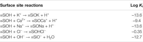
TABLE 1. Equilibrium constants of the surface site reactions at 25 °C (Elakneswaran et al., 2010).
When external chloride ions penetrate CAC, it produces new Kuzel’s and Friedel’s salts, causing an increase in the their content. This is considered to be a result of the precipitation reactions of the species (such as SO42-, Cl−, Al(OH)4-, OH−, and Ca2+) in the pore solution, which is accompanied by other dissolution and precipitation reactions between cement hydrate and pore solution. Similarly, the mass action law is used to describe the phase equilibrium of the dissolution and precipitation reactions.
where Kp is the equilibrium constant of the dissolution/precipitation reaction between the pore solution and hydrate phase p. The dissolution/precipitation reactions considered in this study are presented in the next section. ci,p and γi,p denote the concentration of ion i in the pore solution and its activity coefficient, respectively; the Davies or extended Debye−Huckel equation is used to express the activity coefficient γi,p, [more details about this equation can be seen in (Parkhurst and Appelo, 2013)]; ni,p denotes the stoichiometric coefficient of ion i in the associated reaction. The equilibrium constants for nearly all the hydration products in cement-based materials can be seen in the CEMDATA18 database (Lothenbach et al., 2019).
In saturated CAC, diffusion and electromigration are two driving forces that cause the transport of free ions in the pore solution, which can be described using the Nernst–Planck equation:
where Ji (mol/m2/s) denotes the flux of free ion i; Di (m2/s) is the diffusion coefficient of free ion i in CAC, which will be discussed in detail later; ci (mol/m3) and zi (−) denote the ionic concentration and electric charge number, respectively; ϕ (V) denotes the electric potential. The electric neutrality in CAC should be satisfied when subjected to chloride ingress, and hence,
Combining Eqs 6, 7, the following can be deduced:
According to the continuity equation, we can obtain:
where Qi denotes the source term, which is determined by the physical and chemical interactions between the pore solution and cement hydrate, which is calculated via thermodynamic modelling in Physical and Chemical Interactions Between Pore Solution and Cement Hydrate.
The diffusion coefficient (Di) of free ion i in the pore solution of a porous material is completely different from that in free water because it is affected by the constrictivity and tortuosity of the pore structure (Appelo et al., 2010). Considering that the diffusion coefficient (DCl) of chloride in saturated cement-based materials can be easily measured by rapid chloride migration testing, the diffusion coefficient (Di) of free ion i in CAC is expressed using the following equation:
where
Reactive transport modelling is divided into two modules using the operator splitting algorithm, i.e., the reaction and transport modules (Nardi et al., 2014). The PHREEQC program, a geochemical simulator developed by the United States Geological Survey (USGS), can solve the reaction module (Parkhurst and Appelo, 2013). COMSOL Multiphysics, a commercial finite element method (FEM) software, can solve the transport module (COMSOL, 2021). Hence, a COMSOL-PHREEQC interface must be developed to achieve the interaction between these two modules (Guo et al., 2018; Nardi et al., 2014). COMSOL Multiphysics with MATLAB can connect COMSOL Multiphysics to the MATLAB script (COMSOL, 2021). The IPhreeqc COM allows PHREEQC to be used as a COM server for MATLAB (Charlton and Parkhurst, 2011). Therefore, in this study, the MATLAB scripting environment was selected to establish the COMSOL-PHREEQC interface. The main structure and workflow of the interface are illustrated in Figure 1.
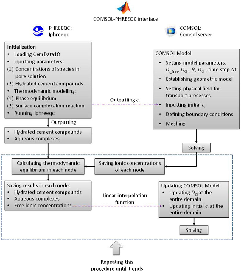
FIGURE 1. Main structure and workflow of the COMSOL-PHREEQC interface to calculate the reactive transport model.
The hydrated cement compounds and concentrations of species in the pore solution are necessary to solve the reactive transport model in cement-based materials and can be obtained from experiments or calculation of GEMS (Kulik et al., 2013; Lothenbach and Winnefeld, 2006; Lothenbach and Zajac, 2019). However, the pore solution and hydrated cement compounds from experiments or GEMS may not be in an equilibrium state in PHREEQC. Thus, as shown in Figure 1, the first step is to initialize such that they are in an equilibrium state in PHREEQC. Simultaneously, the COMSOL model needs to be established, which includes building geometric model, setting material parameters and physical fields, and defining boundary conditions. Then, the concentrations of the free ions from the initialization are output to the COMSOL model as the initial values to calculate the transport process in the first time step. COMSOL is based on FEM, and the concentrations of free ions at each node can be obtained. The values are saved in matrix and then passed to PHREEQC to solve the thermodynamic equilibrium at each FEM node with the hydrated cement compounds from the initialization. When completing the thermodynamic equilibrium calculations at all the nodes, the concentrations of the free ions at the nodes are updated, and then sent back to the COMSOL model as initial values via linear interpolation function to calculate the transport process in the second time step. Meanwhile, the hydrated cement compounds at all the nodes are saved in the form of a matrix for calculating the thermodynamic equilibrium in the third time step. The above procedure is repeated until the calculation ends.
Spiesz et al. (2012) reported that the time to achieve a new thermodynamic equilibrium between the pore solution and cement hydrate is approximately 10 days. Therefore, this 10 was selected as the time step in this model.
To investigate chloride ingress in CAC, CAC cubic specimens with the size of 100 mm × 100 mm × 100 mm were exposed to 3.5% NaCl solution in the literature (Huang, 2020; Huang et al., 2020a), and the free chloride concentrations in the CAC were measured at 30, 60, 90, 120, and 180 days. The coral aggregates presented in Figure 2 were used in their experiment. The chloride ion contents of coral fine and coarse aggregates are 0.6284% and 0.6375, respectively (Wang et al., 2019). In this study, the CAC specimen C30F15 in their experiment was taken as a benchmark example to show the implementation of the reactive transport modelling of chloride ingress in CAC. The experimental results about the free chloride concentration at different exposure times were used to verify the numerical model. The mix proportion, chloride diffusion coefficients, porosity accessible to water, and slump are listed in Table 2. Other details regarding the preparation procedure of CAC and the experiments to measure these characteristics can be found in the literature (Huang et al., 2020a; Huang, 2020). Among the parameters listed in Table 2, the mix proportion is used to calculate the hydrated cement compounds and pore solution, which will be further discussed in the next paragraph. Because CAC itself contains a certain amount of chloride, the rapid chloride migration method cannot measure the chloride diffusion coefficient. Hence, the chloride diffusion coefficient of CAC fitted at the minimum exposure time in Huang et al. (2020a) is used although it is a little unreasonable, as given in Table 2.
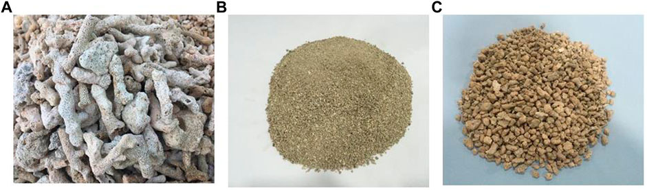
FIGURE 2. (A) Corals; (B) coral fine aggregate; (C) coral coarse aggregate (Huang et al., 2020a).
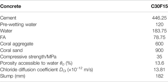
TABLE 2. Mix proportion of CAC in kg/m3, and primary characteristics (Huang et al., 2020a).
The chemical compositions of the cement and FA used in the literature (Huang, 2020; Huang et al., 2020a) are presented in Table 3. According to the mix proportion in Table 2, the hydrated cement compounds and the pore solution can be calculated by employing the GEMS software with the CEMDATA18 and Nagra/PSI TDB thermodynamic databases (Kulik et al., 2013; Lothenbach et al., 2019). It is assumed that the CAC is completely hydrated, and the effect of ageing is neglected. The effect of CO2 in the water or atmosphere on cement hydration is also neglected. The hydrated cement compounds that are considered to participate in the dissolution/precipitation reactions of hydrate phases are calcium silicate hydrate (C−S−H), portlandite (CH), monosulfoaluminate (AFm), ettringite (AFt), Friedel’s salt (Fs), Kuzel’s salt (Ks), and hydrotalcite. Free ions (including Ca2+, K+, Na+, OH−, SO42-, and Cl−) and aqueous complexes (such as AlO2−, HSiO3−, etc.) in the CAC pore solution are taken into account. Therefore, the initial hydrated cement compounds and pore solution obtained by GEMS calculation are given in Tables 4, 5. It has been reported that when the free chloride concentration in pore solution is low, the chemical binding of chloride in cement-based materials is primarily through Kuzel’s salt formation (Mesbah et al., 2011). However, the chloride concentration in CAC is high because coral aggregates contain a considerable amount of chloride. In the experimental study by Wang et al. (2019), Friedel’s salt in CAC was found, which is in line with the results in Table 4. In the study of Huang et al. (2020a), when the exposure time was 30d, the chloride penetration depth was less than 18 mm. The free chloride concentration in the interior of the CAC specimen where the external chloride cannot penetrate should be nearly equal to its initial concentration, and it is 0.17% of concrete weight. Then, according to the mix proportion of CAC and the porosity of CAC, it is 89.29 mol/L of pore solution. The calculation result of the chloride concentration in Table 5 is 105.99. There is a small and acceptable gap between the calculation and experimental results.
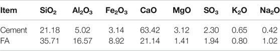
TABLE 3. Chemical compositions (%) of cement and FA (Huang et al., 2020a; Huang, 2020).
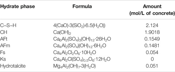
TABLE 4. Hydrated cement compounds.

TABLE 5. Ionic concentration and pH of pore solution.
The specific surface area and surface site density of C−S−H are two key parameters for calculating the surface complexation reactions, and their values are 500 m2/g and 4 × 10³ mol/g, respectively (Pointeau et al., 2006).
According to the experiment of Huang et al. (2020a), the size of the CAC specimen was 100 × 100 × 100 mm3; one surface was exposed to a 3.5% NaCl solution (approximately 0.6 mol/L), and the others were sealed with epoxy resin. In addition, to ensure a constant concentration of chloride, the NaCl solution was periodically replaced. This meant that the Na+ and Cl− concentrations in the external solution nearly maintained 0.6 mol/L throughout the experimental process. In the numerical model, the operator splitting algorithm was used, and the initial values of the ionic concentration in the domain were redefined at each time step (see Figure 1). Thus, the initial values of the Na+ and Cl− concentrations in the external solution were defined as 0.6 mol/L at each time step, instead of the fixed boundary condition widely used in the ionic transport modelling. To reduce the calculation time, the height of the domain of the solution should be as small as possible. The two-dimensional geometrical model was built as shown in Figure 3A, in which the height of the domain of the external solution was chosen as 0.02 m to balance the calculation time and the accuracy. A quadrilateral mesh was adopted, as shown in Figure 3B. The difference in the initial ionic concentrations between the external solution and the CAC specimen was significant, and hence, to improve the convergence of the numerical model, the boundary layer mesh was used to densify the finite element mesh at the interface between the CAC specimen and the external solution. All boundaries in the domain were insulated. In the study of Huang et al. (2020a) The longest time that the specimen was exposed to NaCl solution was 180 days. Herein, the period for simulating chloride ingress for CAC was setas 360 days, giving 36 time steps of 10 days.
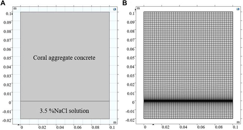
FIGURE 3. (A) Geometrical model; (B) finite element meshing.
The developed numerical model for the reactive transport in CAC is capable of predicting the variations in the hydrate phases, the concentrations of free ions in the pore solution, and the amounts of ions bound by C−S−H with time and space. Considering that the [Cl−]/[OH−] ratio in the pore solution determines the corrosion initiation of reinforcing steel embedded in CAC, the numerical results related to chloride and pH are presented and discussed, including the results of the free chloride concentration and pH in the pore solution, the content of chloride bound by C−S−H, and the amount of Friedel’s salt. In addition, the experimental results for the free chloride concentration in the pore solution in Huang et al. (2020a) are used to verify the numerical model.
When the exposure times are 30, 60, 90, 120, 180, and 360 d, the concentrations of free chloride in the pore solution are shown in Figures 4A‐F respectively. Coral aggregates contain chloride, and hence, free chloride exists in the pore solution of CAC before exposure to the NaCl solution. As presented in Table 5, the initial free chloride concentration is 0.106 mol/L. Thus, the minimum free chloride concentration in the entire domain is 0.106 mol/L of pore solution. The free chloride concentration at the exposure side is the highest, and it gradually decreases with increasing distance from the exposed surface, becoming zero beyond a certain depth. The numerical results in Figure 4 clearly show that the penetration depth of chloride increases with prolonged exposure time. When the CAC specimen is exposed to the external solution for 360 days, the penetration depth of chloride is 23.85 mm (Figure 4F).
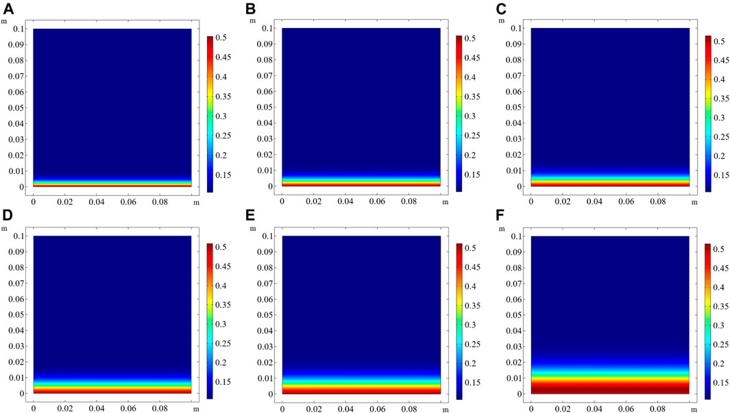
FIGURE 4. Free chloride concentration in the pore solution of CAC at different exposure times (unit: mol/L of pore solution). (A) 30 days, (B) 60 days, (C) 90 days, (D) 120 days, (E) 180 days, (F) 360 days.
The numerical model predicts the pH of the pore solution when the exposure times are 30, 60, 90, 120, 180, and 360 d, which are shown in Figures 5A‐F respectively. Due to the presence of a concentration gradient, OH− moves from high-concentration regions to low-concentration regions. The external solution is neutral, and OH− will move from the pore solution to the external solution. Hence, the pH in the pore solution near the exposed side decreases with increasing exposure time. When the exposure time is 360 days, the pH near the surface is lower than 11.5 (Figure 5F). In addition, similar to the penetration depth of chloride, the regions with reduced pH of the pore solution become thicker with the elapse of time.
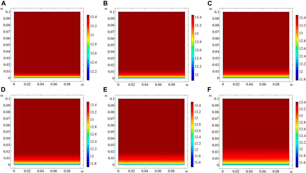
FIGURE 5. pH in the pore solution of CAC at different exposure times. (A) 30 days, (B) 60 days, (C) 90 days, (D) 120 days, (E) 180 days, (F) 360 days.
The physical and chemical binding of chloride has a significant effect on chloride transport in cement-based materials because it can slow down chloride transport, and prolong the time before chloride arrives at the steel surface. When the free chloride concentration decreases, the bound chloride is released into the pore solution as free chloride. The predicted chloride content physically bound by C−S−H at different exposure time is shown in Figure 6. Prior to the ingress of external chloride, some chloride ions in CAC have already been bound by C−S−H or chemically bound by producing Friedel’s salt. With increasing exposure time, increasing number of external chloride ions penetrate CAC, and hence, the amount of chloride bound by C−S−H increases, as shown in Figure 6. The amount of chloride physically bound by C−S−H is closely related to the free chloride concentration in the pore solution. The free chloride concentration at the exposed side is the highest and remains constant (Figure 4). Thus, the amount of chloride physically bound at the exposed side is also the most, which is barely affected by the exposure time.
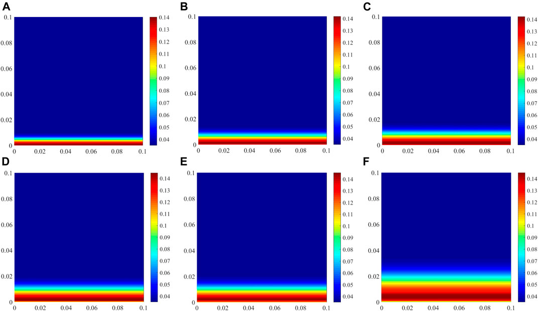
FIGURE 6. Physically bound chloride by C−S−H at different exposure times (unit: mol/L of concrete). (A) 30 days, (B) 60 days, (C) 90 days, (D) 120 days, (E) 180 days, (F) 360 days.
The amount of chemically bound chloride is expressed in the form of the content of Friedel’s salt in the cement hydrate compounds, as shown in Figure 7. As is well known, when OAC is subjected to chloride attack, the chloride concentration in OAC is lower at the early stage, and some chlorides are bound by Kuzel’s salt formation (Mesbah et al., 2011; Tran et al., 2018). With increasing the chloride concentration in OAC from the external environment, Kuzel’s salt is converted into Friedel’s salt (Zibara, 2001), which means that chloride is bound by Friedel’s salt formation. However, because coral aggregates contain chloride, prior to chloride ingress, there are plenty of free chloride ions in the initial pore solution (Table 5 and Figure 4), and some chlorides are directly bound by Friedel’s salt formation (Figure 6). Thus, Kuzel’s salt does not appear in CAC during chloride ingress.
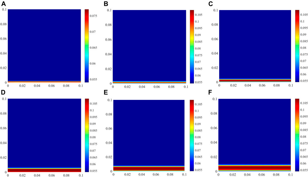
FIGURE 7. Amount of Friedel’s salt in CAC at different exposure times (unit: mol/L of concrete). (A) 30 days, (B) 60 days, (C) 90 days, (D) 120 days, (E) 180 days, (F) 360 days.
One molar of Friedel’s salt contains two molars of chloride, which can be seen from the formula in Table 4. The amount of Friedel’s salt in CAC directly reflects the amount of chemically bound chloride. The amount of bound chloride at the exposed side decreases with prolonging the exposure time. When the exposure time exceeds 60 days, the amount of chloride chemically bound at the exposed side is not the highest in the whole specimen although the free chloride concentration is the highest. Some experimental results indicate that the stability of Friedel’s salt is dependent on the pH of the pore solution, and a decrease in the pH can lead to the dissolution of Friedel’s salt (Suryavanshi and Swamy, 1996). The pH at the exposed side is the lowest in the entire specimen owing to the OH− movement from the pore solution to the external solution, and it decreases with increasing the exposure time (Figure 5). This is unfavourable for the formation of Friedel’s salt. Therefore, the amount of Friedel’s salt on the exposed side decreases, which differs from the physical binding of chloride. However, the variation in the amount of Friedel’s salt in the interior region of the specimen is similar to that of the physical binding.
Huang et al. (2020a) measured the free chloride concentration in CACs with different proportions at different exposure time. Their experimental results of C25F15, C30F15 and C40F15 CAC at 60 days and 180 days are used to verify the numerical model. In Numerical Implementation, C30F15 CAC is used a benchmark example to illustrate the implementation of the numerical model and how to obtain the required parameters from the study of Huang et al. (2020a). Similarly, the required parameters of C25F15 and C40F15 can be obtained. The initial parameters are listed in Tables 6, 7. The diffusion coefficients of chloride in C25F15 and C40F15 CAC used in the numerical model are 15.28 × 10⁻¹² and 12.71 × 10⁻¹², respectively.
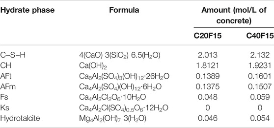
TABLE 6. Hydrated cement compounds of CACs with C20F15 and C40F15.
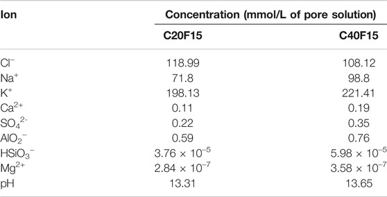
TABLE 7. Ionic concentration and pH of pore solution of CACs with C20F15 and C40F15.
Comparisons between the experimental and numerical results for free chloride in C25F15, C30F15 and C40F15 are shown in Figures 8A‐C respectively. The results for C30F15 CAC are presented in Figure 4, which are represented in Figure 8B using traditional 2D plots. It is noted that the free chloride concentration is versus the CAC weight in their experimental results, and the free chloride concentration in the numerical results needs to be converted according to the mix proportion of CAC and the porosity of CAC.
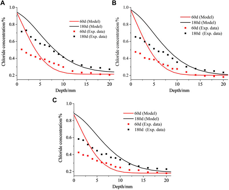
FIGURE 8. Comparison between experimental and numerical results about free chloride concentration: (A) C25F15; (B) C30F15; (C) C40F15. Note that all the experimental data in the figure are from Huang et al. (2020a).
By comparing the numerical and experimental results in Figure 8, it is clear that the numerical model overestimates the free chloride concentration in the surface layer of the specimen, especially when the distance from the exposed side is less than 5 mm. However, the numerical results agree well with the experimental results in the interior of the specimen. Doubt may arise as to whether the developed numerical model can accurately predict the chloride transport in CAC. In the experiment of Huang et al. (2020a), free chloride was obtained from CAC powder using distilled water extraction. At the end of the exposure, all the specimens were placed indoors for 7 days and then dried for 24 h to remove the moisture in the surface layer of CAC before they were milled using a concrete pulveriser. These processes to remove moisture significantly affect the chloride transport, especially in the surface layer of the CAC specimen. It should be noted that these processes occurred at the end of the chloride ingress for CAC, and it is unnecessary to consider them in the reactive transport modelling of chloride ingress for saturated CAC. In other words, the post-processing about the experimental results of (Huang et al., 2020) was not included by the numerical model. This is the primary reason why the numerical model does not agree with the concentration of the free chloride ion in the surface layer of the CAC specimen. However, the processes hardly affect the free chloride concentration measurement in the interior of the CAC specimen, and the chloride ingress is predicted well with the numerical model in this region. Thus, the numerical model can predict the chloride ingress for saturated CAC.
The diffusion coefficient of chloride in the pore solution of CAC is a key input parameter for simulating ionic transport, and this parameter is constant in this study. However, Friedel’s salt formation during chloride ingress causes a less porous structure of cement-based materials (Yuan et al., 2009). Thus, chloride ingress results in a decrease in the diffusion coefficient of chloride owing to the increase in the content of Friedel’s salt (see Figure 7). In practice, chloride ingress into saturated CAC generally occurs in an underwater environment, which is accompanied by the decalcification of cement hydrates. This can also be seen from the benchmark example, in which the numerical model predicts the CH content in CAC at different exposure time, as shown in Figure 9. It is clear that the CH amount decreases with prolonged exposure time, especially in the vicinity of the exposed side. Decalcification would result in a more porous structure of CAC, leading to an increase in the diffusion coefficient of chloride in the pore solution of CAC. However, the positive effect of decalcification and the negative effect of Friedel’s salt formation on the diffusion coefficient of chloride only appears in the local region close to the external solution. These effects are more significant with time, and the local region will increase. Thus, the diffusion coefficient of chloride varies with time and space. However, it is difficult to consider this in the reactive transport modelling. This is the limit of the model developed in this study. This may also be another reason for the gap between the numerical and experimental results shown in Figure 8.
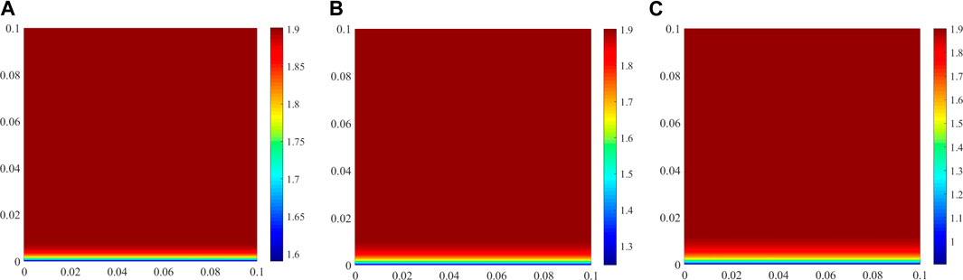
FIGURE 9. Amount of CH in CAC at different exposure times (unit: mol/L of concrete). (A) 30 days, (B) 180 days, (C) 360 days.
Reactive transport modelling was developed in this study to investigate chloride ingress in CAC. A COMSOL-PHREEQC interface was established to solve the numerical model based on the MATLAB program. The experimental investigation of Huang et al. (2020a) was taken as an example to illustrate the implementation of reactive transport modelling in CAC. The free chloride concentration and pH in the CAC pore solution, and the physically and chemically bound chloride are predicted. The results indicate that the developed numerical model is capable of predicting chloride transport behaviour in CAC.
Kuzel’s salt does not appear in the cement hydrate compounds of CAC during chloride ingress, which is different from OAC. The numerical results clearly indicate that the penetration depth of chloride in CAC gradually increases as the exposure time is prolonged. When exposed to external chloride solution, the decrease in the pH of the CAC pore solution has a significant influence on the formation of Friedel’s salt, which is detrimental to the chemical binding of chloride.
The raw data supporting the conclusions of this article will be made available by the authors, without undue reservation.
BG: Numerical modelling, Writing-Original draft preparation, Funding acquisition. ZL: Investigation, Writing-Review and Editing. QF: Analysis, Methodology. YW: Conceptualization, Analysis. DH: Conceptualization, Methodology. DN: Conceptualization, Supervision.
This study is supported by the Nature Science Foundation of China (51908453), China Postdoctoral Science Foundation (2020M673607XB and 2020T130497), Scientific Research of Shanxi Provincial Department of Education (20JK0710), Independent Research and Development project of State Key Laboratory of Green Building in Western China (LSZZ202113).
The authors declare that the research was conducted in the absence of any commercial or financial relationships that could be construed as a potential conflict of interest.
All claims expressed in this article are solely those of the authors and do not necessarily represent those of their affiliated organizations, or those of the publisher, the editors and the reviewers. Any product that may be evaluated in this article, or claim that may be made by its manufacturer, is not guaranteed or endorsed by the publisher.
Angst, U., Elsener, B., Larsen, C. K., and Vennesland, Ø. (2009). Critical Chloride Content in Reinforced concrete - A Review. Cement Concrete Res. 39 (12), 1122–1138. doi:10.1016/j.cemconres.2009.08.006
Angst, U. M. (2019). A Critical Review of the Science and Engineering of Cathodic protection of Steel in Soil and concrete. Corrosion Journal.ORG. 12 (75), 1420–1433. doi:10.5006/3355
Appelo, C. A. J., Van Loon, L. R., and Wersin, P. (2010). Multicomponent Diffusion of a Suite of Tracers (HTO, Cl, Br, I, Na, Sr, Cs) in a Single Sample of Opalinus clay. Geochimica et Cosmochimica Acta 74 (4), 1201–1219. doi:10.1016/j.gca.2009.11.013
Baroghel-Bouny, V., Thiéry, M., and Wang, X. (2011). Modelling of Isothermal Coupled Moisture-Ion Transport in Cementitious Materials. Cement Concrete Res. 41 (8), 828–841. doi:10.1016/j.cemconres.2011.04.001
Charlton, S. R., and Parkhurst, D. L. (2011). Modules Based on the Geochemical Model PHREEQC for Use in Scripting and Programming Languages. Comput. Geosciences 37 (10), 1653–1663. doi:10.1016/j.cageo.2011.02.005
COMSOL (2021). COMSOL Multiphysics. Version 5.5. Available from: www.comsol.com.
Da, B., Yu, H., Ma, H., Tan, Y., Mi, R., and Dou, X. (2016). Chloride Diffusion Study of Coral concrete in a marine Environment. Construction Building Mater. 123, 47–58. doi:10.1016/j.conbuildmat.2016.06.135
Elakneswaran, Y., Iwasa, A., Nawa, T., Sato, T., and Kurumisawa, K. (2010). Ion-cement Hydrate Interactions Govern Multi-Ionic Transport Model for Cementitious Materials. Cement Concrete Res. 40 (12), 1756–1765. doi:10.1016/j.cemconres.2010.08.019
Elakneswaran, Y., Nawa, T., and Kurumisawa, K. (2009). Electrokinetic Potential of Hydrated Cement in Relation to Adsorption of Chlorides. Cement Concrete Res. 39 (4), 340–344. doi:10.1016/j.cemconres.2009.01.006
Elakneswaran, Y., Nawa, T., and Kurumisawa, K. (2009). Influence of Surface Charge on Ingress of Chloride Ion in Hardened Pastes. Mater. Struct. 42, 83–93. doi:10.1617/s11527-008-9368-8
Gui, W., Hu, X., and Liang, L. (2020). Normal Distribution Analysis of Fracture Parameters of Alkali-Activated Slag Seawater Column Coral Aggregate concrete. Theor. Appl. Fracture Mech. 110, 102794. doi:10.1016/j.tafmec.2020.102794
Guo, B., Hong, Y., Qiao, G., and Ou, J. (2018). A COMSOL-PHREEQC Interface for Modeling the Multi-Species Transport of Saturated Cement-Based Materials. Construction Building Mater. 187, 839–853. doi:10.1016/j.conbuildmat.2018.07.242
Guo, B., Hong, Y., Qiao, G., Ou, J., and Li, Z. (2018). Thermodynamic Modeling of the Essential Physicochemical Interactions between the Pore Solution and the Cement Hydrates in Chloride-Contaminated Cement-Based Materials. J. Colloid Interf. Sci. 531, 56–63. doi:10.1016/j.jcis.2018.07.005
Guo, B., Qiao, G., Li, D., and Ou, J. (2021). Multi-species Reactive Transport Modeling of Electrochemical Corrosion Control in Saturated concrete Structures Including Electrode Reactions and Thermodynamic Equilibrium. Construction Building Mater. 278, 122228. doi:10.1016/j.conbuildmat.2020.122228
Haynes, W. M., Lide, D. R., and Bruno, T. J. (2014). Handbook of Chemistry and Physics. Boca Raton: CRC Press.
Hou, B., Li, X., Ma, X., Du, C., and Zhang, D. (2017). The Cost of Corrosion in China. NPJ Mat. Degrad. 1 (1), 1–10. doi:10.1038/s41529-017-0005-2
Huang, D. (2020). Chloride Transport Behavior of Coral Aggregate concrete under Extreme Hot and Humid Environment, PhD Thesis. China: Xi'an University of Architecture and Technology.
Huang, D., Niu, D., Zheng, H., Su, L., Luo, D., and Fu, Q. (2020a). Study on Chloride Transport Performance of Eco-Friendly Coral Aggregate concrete in marine Environment. Construction Building Mater. 258, 120272. doi:10.1016/j.conbuildmat.2020.120272
Kari, O. P., Elakneswaran, Y., Nawa, T., and Puttonen, J. (2013). A Model for a Long-Term Diffusion of Multispecies in concrete Based on Ion-Cement-Hydrate Interaction. J. Mater. Sci. 48 (12), 4243–4259. doi:10.1007/s10853-013-7239-3
Kulik, D. A., Wagner, T., Dmytrieva, S. V., Kosakowski, G., Hingerl, F. F., Chudnenko, K. V., et al. (2013). GEM-selektor Geochemical Modeling Package: Revised Algorithm and GEMS3K Numerical Kernel for Coupled Simulation Codes. Comput. Geosci-uk 17 (1), 1–24.
Lehner, P., Konečný, P., and Ghosh, P. (2021). Variation of Durability and Strength Parameters of Pumice Based Mixtures. Materials 14, 3674. doi:10.3390/ma14133674
Li, H., Xiao, H., Guan, X., Wang, Z., and Yu, L. (2014). Chloride Diffusion in concrete Containing Nano-TiO2 under Coupled Effect of Scouring. Composites B: Eng. 56, 698–704. doi:10.1016/j.compositesb.2013.09.024
Liang, X., Yin, S., and Hu, C. (2021). Environmental Reduction Factors of BFRP Bars in Coral Aggregate concrete in High Temperature and High Humidity Environments. Structures 33, 3017–3024. doi:10.1016/j.istruc.2021.06.021
Liang, X., and Yin, S. (2021a). Mechanical Properties and Gas Permeability of Coral Aggregate concrete Incorporating Supplementary Cementitious Materials. Construction Building Mater. 302, 124237. doi:10.1016/j.conbuildmat.2021.124237
Liu, B., Guo, J., Zhou, J., Wen, X., Deng, Z., Wang, H., et al. (2020). The Mechanical Properties and Microstructure of Carbon Fibers Reinforced Coral concrete. Construction Building Mater. 249, 118771. doi:10.1016/j.conbuildmat.2020.118771
Liu, Q.-f., Easterbrook, D., Yang, J., and Li, L.-y. (2015). A Three-phase, Multi-Component Ionic Transport Model for Simulation of Chloride Penetration in concrete. Eng. Structures 86, 122–133. doi:10.1016/j.engstruct.2014.12.043
Lothenbach, B., Kulik, D. A., Matschei, T., Balonis, M., Baquerizo, L., Dilnesa, B., et al. (2019). Cemdata18: A Chemical Thermodynamic Database for Hydrated Portland Cements and Alkali-Activated Materials. Cement Concrete Res. 115, 472–506. doi:10.1016/j.cemconres.2018.04.018
Lothenbach, B., and Winnefeld, F. (2006). Thermodynamic Modelling of the Hydration of portland Cement. Cement Concrete Res. 36 (2), 209–226. doi:10.1016/j.cemconres.2005.03.001
Lothenbach, B., and Zajac, M. (2019). Application of Thermodynamic Modelling to Hydrated Cements. Cem. Concr. Res. 105779 (13). doi:10.1016/j.cemconres.2019.105779
Mesbah, A., François, M., Cau-dit-Coumes, C., Frizon, F., Filinchuk, Y., Leroux, F., et al. (2011). Crystal Structure of Kuzel's Salt 3CaO·Al2O3·1/2CaSO4·1/2CaCl2·11H2O Determined by Synchrotron Powder Diffraction. Cement Concrete Res. 41 (5), 504–509. doi:10.1016/j.cemconres.2011.01.015
Nardi, A., Idiart, A., Trinchero, P., de Vries, L. M., and Molinero, J. (2014). Interface COMSOL-PHREEQC (iCP), an Efficient Numerical Framework for the Solution of Coupled Multiphysics and Geochemistry. Comput. Geosciences 69, 10–21. doi:10.1016/j.cageo.2014.04.011
Parkhurst, D. L., and Appelo, C. A. J. (2013). Description of Input and Examples for PHREEQC Version 3−A Computer Program for Speciation, Batch-Reaction, One-Dimensional Transport, and Inverse Geochemical Calculations. U.S. Geol. Surv.
Pointeau, I., Reiller, P., Macé, N., Landesman, C., and Coreau, N. (2006). Measurement and Modeling of the Surface Potential Evolution of Hydrated Cement Pastes as a Function of Degradation. J. Colloid Interf. Sci. 300 (1), 33–44. doi:10.1016/j.jcis.2006.03.018
Spiesz, P., Ballari, M. M., and Brouwers, H. J. H. (2012). RCM: A New Model Accounting for the Non-linear Chloride Binding Isotherm and the Non-equilibrium Conditions between the Free- and Bound-Chloride Concentrations. Construction Building Mater. 27 (1), 293–304. doi:10.1016/j.conbuildmat.2011.07.045
Suryavanshi, A. K., and Narayan Swamy, R. (1996). Stability of Friedel's Salt in Carbonated concrete Structural Elements. Cement Concrete Res. 26 (5), 729–741. doi:10.1016/s0008-8846(96)85010-1
Tang, L., and Nilsson, L.-O. (1995). A New Approach to the Determination of Pore Distribution by Penetrating Chlorides into concrete. Cement Concrete Res. 25 (4), 695–701. doi:10.1016/0008-8846(95)00058-k
Tran, V. Q., Soive, A., and Baroghel-Bouny, V. (2018). Modelisation of Chloride Reactive Transport in concrete Including Thermodynamic Equilibrium, Kinetic Control and Surface Complexation. Cement Concrete Res. 110, 70–85. doi:10.1016/j.cemconres.2018.05.007
Van Quan, T., Soive, A., Bonnet, S., and Khelidj, A. (2018). A Numerical Model Including Thermodynamic Equilibrium, Kinetic Control and Surface Complexation in Order to Explain Cation Type Effect on Chloride Binding Capability of concrete. Constr. Build. Mater. 191, 608–618.
Wang, Y., Zhang, S., Niu, D., Su, L., and Luo, D. (2019). Effects of Silica Fume and Blast Furnace Slag on the Mechanical Properties and Chloride Ion Distribution of Coral Aggregate concrete. Construction Building Mater. 214, 648–658. doi:10.1016/j.conbuildmat.2019.04.149
Wattanachai, P., Otsuki, N., Saito, T., and Nishida, T. (2009). A Study on Chloride Ion Diffusivity of Porous Aggregate Concretes and Improvement Method. Jsce J. Mater. Concrete Structures Pavements 65 (1), 30–44. doi:10.2208/jsceje.65.30
Wu, Z., Zhang, J., Yu, H., and Ma, H. (2020). 3D Mesoscopic Investigation of the Specimen Aspect-Ratio Effect on the Compressive Behavior of Coral Aggregate concrete. Composites Part B: Eng. 198, 108025. doi:10.1016/j.compositesb.2020.108025
Yu, H., Da, B., Ma, H., Dou, X., and Wu, Z. (2020). Service Life Prediction of Coral Aggregate concrete Structure under Island Reef Environment. Construction Building Mater. 246, 118390. doi:10.1016/j.conbuildmat.2020.118390
Yu, H., Da, B., Ma, H., Zhu, H., Yu, Q., Ye, H., et al. (2017). Durability of concrete Structures in Tropical Atoll Environment. Ocean Eng. 135, 1–10. doi:10.1016/j.oceaneng.2017.02.020
Yuan, Q., Shi, C., De Schutter, G., Audenaert, K., and Deng, D. (2009). Chloride Binding of Cement-Based Materials Subjected to External Chloride Environment - A Review. Construction Building Mater. 23 (1), 1–13. doi:10.1016/j.conbuildmat.2008.02.004
Yuan, Q., Shi, C., De Schutter, G., Deng, D., and He, F. (2011). Numerical Model for Chloride Penetration into Saturated concrete. J. Mater. Civ. Eng. 23 (3), 305–311. doi:10.1061/(asce)mt.1943-5533.0000168
Zhang, L., Niu, D., Wen, B., Peng, G., and Sun, Z. (2020). Corrosion Behavior of Low alloy Steel Bars Containing Cr and Al in Coral concrete for Ocean Construction. Construction Building Mater. 258, 119564. doi:10.1016/j.conbuildmat.2020.119564
Zhou, L., Guo, S., Zhang, Z., Shi, C., Jin, Z., and Zhu, D. (2021). Mechanical Behavior and Durability of Coral Aggregate concrete and Bonding Performance with Fiber-Reinforced Polymer (FRP) Bars: A Critical Review. J. Clean. Prod. 289, 125652. doi:10.1016/j.jclepro.2020.125652
Keywords: coral aggregates concrete, chloride ingress, reactive transport modelling, chloride binding, corrosion
Citation: Guo B, Li Z, Fu Q, Wang Y, Huang D and Niu D (2021) Reactive Transport Modelling of Chloride Ingress in Saturated Coral Aggregate Concrete. Front. Mater. 8:755241. doi: 10.3389/fmats.2021.755241
Received: 08 August 2021; Accepted: 22 September 2021;
Published: 12 October 2021.
Edited by:
Anuj Kumar, Natural Resources Institute Finland (Luke), FinlandReviewed by:
Petr Lehner, VSB-Technical University of Ostrava, CzechiaCopyright © 2021 Guo, Li, Fu, Wang, Huang and Niu. This is an open-access article distributed under the terms of the Creative Commons Attribution License (CC BY). The use, distribution or reproduction in other forums is permitted, provided the original author(s) and the copyright owner(s) are credited and that the original publication in this journal is cited, in accordance with accepted academic practice. No use, distribution or reproduction is permitted which does not comply with these terms.
*Correspondence: Bingbing Guo, Z3VvYmluZ2JpbmcyMTJAMTYzLmNvbQ==; Zhenming Li, Wi5saS0yQHR1ZGVsZnQubmw=
Disclaimer: All claims expressed in this article are solely those of the authors and do not necessarily represent those of their affiliated organizations, or those of the publisher, the editors and the reviewers. Any product that may be evaluated in this article or claim that may be made by its manufacturer is not guaranteed or endorsed by the publisher.
Research integrity at Frontiers
Learn more about the work of our research integrity team to safeguard the quality of each article we publish.