
94% of researchers rate our articles as excellent or good
Learn more about the work of our research integrity team to safeguard the quality of each article we publish.
Find out more
ORIGINAL RESEARCH article
Front. Mater., 10 November 2021
Sec. Structural Materials
Volume 8 - 2021 | https://doi.org/10.3389/fmats.2021.754284
This article is part of the Research TopicInclusion/Precipitate Engineering and Thermo-Physical Properties in Liquid Steels and AlloysView all 8 articles
 A. Raviraj1*
 S. Spooner2J. Li3N. Kourra4J. Warnett1
 G. Abbel5
 W. Tiekink5M. A. Williams1C. Davis1
 S. Sridhar6
The authors present a series of complementary test methods which were developed and used to investigate reactions between high aluminium steel and silica rich inclusions. Non-metallic inclusions (NMIs) cause many defects in the final steel product, therefore the ability to track their size, morphology and composition and correlate this with fundamental reaction kinetics provides important knowledge to support the production of clean quality steel products. Novel steel grades such as TRIP, TWIP and low-density steels have high aluminium contents; aluminium is a readily oxidisable species presenting the potential for instability and excessive reaction with commonly used mould powders that contain silica. A novel combination of techniques including HT-CLSM (High-Temperature Confocal Laser Scanning Microscope), XCT (X-ray computed tomography) and SEM/EDS (scanning electron microscopy/electron dispersive spectroscopy) have been used to study the interaction of entrained mould powder inclusions with steel at high temperatures simulating industrial conditions. This report presents a discussion on the development of techniques and samples to achieve representative and repeatable results that can provide information on the complex chemical and physical interaction phenomena with confidence. Each experimental technique had its own learning points and consequent results. Outcomes presented include possible confirmation of the chemical reaction rate controlling step being aluminium mass transfer; heterogeneous local environmental conditions including fluidity and chemical composition; and occurrence of spontaneous emulsification where the mould powder inclusion breaks apart into a cloud of smaller fragments.
Non-metallic inclusions cause various defects in steel such as slag spots and line defects (Zhang et al., 2002). The reactions between inclusions and the liquid steel in the continuous casting mould directly affect inclusion behaviour. Removing inclusions from liquid steel in the continuous casting process is critical to reduce steel defects and product high quality steels as well as preventing unwanted reactions between the steel and the mould slags that could change important properties of the mould powder such as viscosity.
Inclusions can be characterised by evaluating their size, distribution, morphology and chemical composition (Zhang and Thomas, 2003). There are a variety of methods that can be used to detect inclusions in the solid steel as well as in the liquid steel (Zhang et al., 2002). Conventional methods such as optical microscopy, ultrasound testing, laser induced spectrometry, XCT (x-ray computed tomography) and automated scanning electron microscopy (SEM) are often used to detect inclusions (Zhang et al., 2002). SEM with energy-dispersive X-ray (EDX) spectrometry can give chemical analysis and metallographic images (Pretorius et al., 2015). More modern equipment in the form of an automated system allows the entire sample to be scanned giving more statistical information of types and sizes of inclusions over large areas. Indirect methods are also widely adopted in industry to determine the number of inclusions and consist of determining the chemical composition of the slag as well as the conditions of the refractory and composition of the liquid steel giving information of how much of the alloying elements have reacted with the slag. The total oxygen content of the steel samples can be directly related to the presence of inclusions (Ren et al., 2014). The equipment used for this method can also measure the dissolved nitrogen in the sample, which can then be used to analyse the nitrogen pick up (Zhangfeng, 2006) and hence air absorption by the liquid steel bath, which is directly related to reoxidation.
Several methods can directly measure inclusions in the three-dimensional steel matrix. Using ultrasound or X-rays can scan through the sample or other techniques can be used to separate the inclusion from the steel (Lopez et al., 2014). Conventional ultrasonic scanning uses a transducer to emit sound pressure waves that are transferred into the sample with the help of a coupling gel (Bastien, 1977; Eckel et al., 1998). An oscilloscope is used to compare the signals emitted to then indicate the quality of the sample. This non-destructive test method can be used to detect inclusions larger than 20 μm in solidified steel samples (Zhang and Thomas, 2003). X-rays can also be used as a non-destructive test method that uses the variation of X-rays attenuated through the solid steel to image inclusions as they have a different density (Wells, 2007). Destructive methods such as chemical dissolution use acids to dissolve the steel and extract the inclusions (Zhang and Thomas, 2003). Further characterisation can be done using SEM/EDS to study the morphology and composition, revealing the three-dimensional nature of inclusions. The disadvantage of this technique is that the acid used will also dissolve any FeO, MnO, CaO, and MgO in the inclusion so it can only be used to detect and analyse Al2O3 and SiO2. Electrolysis can be used for relatively large samples of steel of up to 2 kg by immersion in a solution of iron chloride or iron sulphate to reveal individual and intact inclusions, however this can break up inclusion clusters into smaller particles (Zhang et al., 2017).
The detection methods used to study the surface of the inclusions or the steel surface often involves some destruction of the sample, therefore, the reactions and interactions of inclusions with liquid steel have not been able to study the interactions of an inclusion wholly enclosed in the liquid steel and its 3D nature. Therefore, a combination of techniques need to be used to study the kinetics of inclusion - steel reactions as well as producing new information on the 3D interface of the two phases during the reaction.
The systems under investigation in this report are low and high aluminium steels (aluminium contents of 0.04 wt. % and 1 wt. %, respectively), combined with a commercially available mould slag designed for the casting of low carbon high strength steels. The predominant agent of interest within the mould powder is SiO2 as the major chemical potential for the reaction held between aluminium and silicon dioxide is expected to drive any significant change in the mould powder inclusion. Under experimental conditions, the reaction is expected to follow the reaction given in Eq. 1 where aluminium is in the metal and silicon dioxide is in the slag. The Gibbs Free Energy calculation shows that the reaction will occur favourably as the value is negative at 1873 K as shown in Eq. 2.
where the species in the [] parenthesis are in the metal phase and the species in the () parenthesis are in the slag/inclusion phase.
By taking into account the key gaps in the literature, it is clear that the methods that are currently being used to study inclusions have not been able to directly investigate inclusions within the steel matrix, without dissolving the steel (Zhang et al., 2017). This research focuses on isolating a single inclusion in a small sample, the environment around it is also small, therefore the inclusion has the potential to affect the steel sample chemistry, which is not representative of the industrial situation where there is a large amount of liquid around one inclusion. To try and replicate this is the challenge investigated in the experimental techniques described in this report. The experiments outlined involve four different phases: slag, metal, container, and gas. At such high temperatures, all reactants have to be taken into consideration including the atmosphere and the container. Therefore, designing an experimental technique to isolate the reactions of interest (metal phase and slag phase) is a challenge, and the relative advantages and disadvantages of the approaches presented have been considered.
The main goal of this paper is to explore the development of a method to study the interaction between steel and an inclusion and also the floatation rates of the inclusions in the liquid steel, which are influenced by the composition (density) and size of the inclusions. These factors are affected by the exchange of material across the inclusion-steel interface driven by the system’s starting chemical potential.
All the experimental techniques use the same materials processed in different ways and tested using a combination of the experimental methods outlined in this section.
The materials listed below were provided by Tata Steel Europe, Ijmuiden for the purpose of this study.
Bulk metal alloys were produced at Tata Steel Europe, Ijmuiden, with concentrations of 0.04 wt% and 1 wt% aluminium as shown in Table 1. The 0.04 wt. % Al sample is a piece from slab material from the production plant and the 1 wt% Al sample is from casts made at Tata Steel Europe’s vacuum induction melting facilities in 25 kg ingots. The steel had a melting temperature of 1773 K.
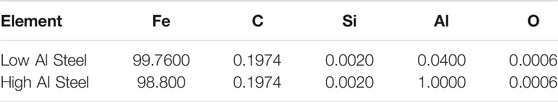
TABLE 1. Composition of iron alloys measured using Spark OES, all wt%.
A commercial iron powder was purchased, named as low carbon carbonyl iron powder (CIP CC). The composition of the iron powder as provided is shown in Table 2.

TABLE 2. Composition of the iron powder as provided by BASF measured using ICP, all wt. %.
A commercial mould powder was used with composition shown in Table 3 with a melting temperature of 1513 K.

TABLE 3. Composition of mould slag powder was measured using ICP, all wt%.
Spherical artificial mould slag inclusions are required for the experiments because mould slag can be entrapped in the liquid steel during casting because there is high wettability between the slag and steel. The mould powder has a lower melting temperature than the steel therefore the liquid mould slag particles become spherical in the liquid steel due to interfacial tension minimisation.
To produce the artificial spherical inclusion particles, the mould powder particles are decarburised at 600°C while the slag is not liquid, then the particles are heated above their melting temperature at 1,200°C in an argon atmosphere on a non-wetting graphite plate where they ball up into spheres, these are cooled and then sieved to obtain particles between 250 and 350 µm. Carbon that is in the original mould powder from impurities such as graphite or soot are burnt away during the 600oC preheat and not dissolved in the slag.
The principles of operation for the HT-CLSM are described in (Raviraj et al., 2021) and the equipment can be used for a variety of experiments with direct observation of the sample. In this work the HT-CLSM is used for two types of tests, described in Experimental Techniques with the general principles covered here (and described in more detail in Samples of a maximum size of 1 cm diameter are placed into an alumina crucible which is then loaded into the HT-CLSM chamber. The preparation of the specific samples relevant for the work on slag-steel interactions are described in detail in a later section. The chamber is vacuumed with a high purity argon gas (99.999%) three times to ensure that no oxygen is present to give unwanted oxidation. The sample is preheated to 473 K using a slow heating rate to ensure the longevity of the halogen lamp. The sample was then heated with varying heating regimes (depending on the test method), held for a period of time and then quenched at a rate of 1500 K per minute from 1893 to 973 K and then cooled further at a rate of 300 K per minute to room temperature. The HT-CLSM can also be used to observe the steel in-situ.
A steel sample of size 6 mm diameter can be scanned using a Zeiss Versa 520d X-Ray CT scanner using a 160 kV source, with an exposure time of 13 s and a magnification of 0.4 x. The resultant voxel size is 27 microns with 3,235 projections. The data were analyzed using Avizo, a 3D visualization software that can segment the sample phases based on gray scale and examine features such as the size of the inclusion and any porosity. This can be done quantitatively given the known voxel size (Assis et al., 2015).
After scanning and Avizo analysis, the samples were mounted in resin using EpoThin™ 2 Epoxy Resin and EpoThin™ 2 Hardener. The samples were then sectioned (where the inclusion was identified from the XCT scan) and polished using a Buehler AutoMetTM 250 Pro Grinder-Polisher with a finishing diamond polish of 3 µm. The SEM used for microscopic investigations was a Zeiss Supra 55VP and EDX was carried out on any inclusions present and the surrounding matrix.
To understand the behaviour of mould slag inclusions in liquid steel a test method must be developed in order to allow for a known starting condition (inclusion size, shape, chemistry, and steel chemistry), measurement of conditions (heating rate, temperature, times) and final analysis (inclusion size, shape, chemistry and steel chemistry including local to the inclusion). Material taken from full scale industrial production has inherent limitations to the scientific understanding which can be extracted because of the precise reaction times and temperatures being unknown. The origin of inclusions and their starting properties cannot be known to significant levels of confidence, measurements of time, temperature, and other physical conditions are difficult due to both equipment capabilities and heterogeneity within a process.
In order to study an inclusion entrained inside a steel sample, a powder press sample was developed which could then be melted using the HT-CLSM, scanned in 3D using XCT, and analysed using Avizo software for visualisation and quantification of the inclusion. This test was designed to investigate the chemical reaction between the slag and steel as well as any information to calculate the floatation time of a known size inclusion. The outcomes and learning from the powder press samples were used to inform further experimental assessments for reactions of an inclusion inside a steel matrix.
In order to make a sintered steel sample, Fe powder is mixed with a binder and pressed into a layer. Several layers can be put on top of each other to make one bar. Artificial inclusions can be put between two layers or mixed into one of the layers. Individual layers are sintered at 1400 K for 30 min in a furnace and then pressed at 1 MPa using pellet press. Inclusions produced according to the approach discussed in Decarburized Mould Powder to Form Spherical Inclusions are added in between the layers building up the sample until the required thickness is achieved. The completed sample is pressed under a pressure of 20 MPa then placed on a zirconia sheet into a furnace heating at a rate of 393–413 K per hour to a dwell of 2 h at 1373 K in a hydrogen atmosphere. This is to ensure that the inclusion does not melt as the temperature is lower than the melting temperature of the inclusion. The size of the pellet is 5 mm diameter with a 6 mm height.
The equipment that is used for this experimental set up is the Yonekura HT-CLSM, Zeiss Versa 520 X-Ray CT scanner and the Zeiss Supra 55VP SEM.
The sample was heated in a HT-CLSM to 1673 K at a rate of 473 K per minute then slowly heated to 1823 K at a rate of 323 K per minute and held for a time of 5–10 min then cooled at a rate of 573 K per minute to 973 K for 2 min to avoid shock of the halogen bulk and then cooled to room temperature. These times were selected to ensure that the inclusion has enough time to react with the steel.
Figure 1 shows an XCT image of a powder press sample before melting. The inclusion is not in the centre of the sample, although this was the initial aim during the sample build and is not spherical due to deformation during the pellet making. In the XCT images, the light grey is the steel, the medium grey is the inclusion and the dark grey/black is the porosity. As it can be seen, the inclusion has some porosity around it. This could be due to the inclusion being softer and more easily deformed during the making of the pellet. The porosity in the steel matrix is also shown in Figure 2.
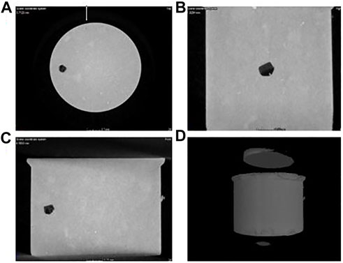
FIGURE 1. An X-CT image of a powder press sample before CLSM melting: (A) top view of the sample showing the position of the inclusion, (B) side view of the sample showing the position of the inclusion, (C) another side view of the sample showing the position of the inclusion, (D) 3D volume of the powder pressed pellet where the inclusion is the darker area, and light grey is steel.
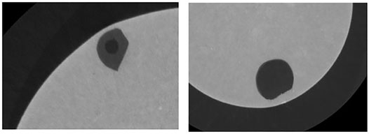
FIGURE 2. Two samples shown before melting which shows the positions and morphology of the inclusions within the steel matrix where the light grey is steel, medium grey is the inclusion/slag phase and the dark grey/black is porosity.
This test method was very time consuming as the sample needed to be XCT scanned before melting to determine the inclusion location and morphology which allowed orientation of sample for melting to be determined (inclusion in lower part of sample to allow maximum length of flotation). This is important as the inclusion does have a tendency to float. The sample also had to be XCT scanned after melting to find the new location and morphology of the inclusion. A high resolution XCT scan takes 26 h. There was also a lot of small porosity in the metal phase which, because the slag phase melted at a lower temperature than the steel, this could allow the slag to separate throughout the porosity network first preventing a bulk inclusion/steel reaction study to be observed as seen in Figure 3 which is XCT image after melting. Therefore, the method of sample preparation affected the morphology of the initial inclusion which might affect the reaction of the inclusion with the steel, providing uncertainties and errors in the experimental approach. Air pockets in, or attached to the inclusion, could cause the inclusion to float quicker in a steel sample.
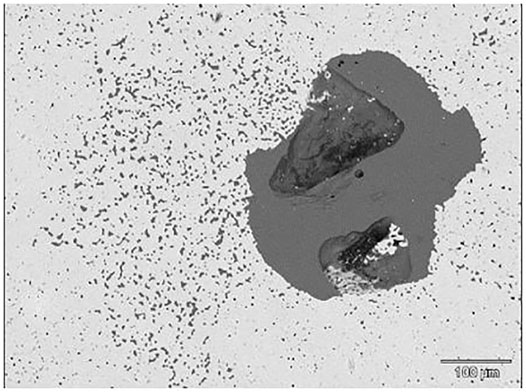
FIGURE 3. XCT ortho slice of a pre-melted powder press sample showing the inclusion in dark grey, steel matrix in light grey and darker spots of porosity within the steel matrix and inclusion.
The aim of this test design was to investigate high temperature reactions for an inclusion completely entrained within a steel matrix, adapting the approach based on the findings from the powder press samples. The new sample design consisted of a machined cylinder from a solid cast steel sample with an inclusion placed into the middle using a drilled hole.
The pellet samples are machined by electrical discharge machining (EDM). A mould slag particle is placed into the drilled hole and then the hole is filled with iron powder. A steel stopper was used to press the hole close. These samples were made in two sizes: 3 mm diameter, 4 mm height and 5 mm diameter, 6 mm height. A XCT 3D image is shown below in Figure 4.
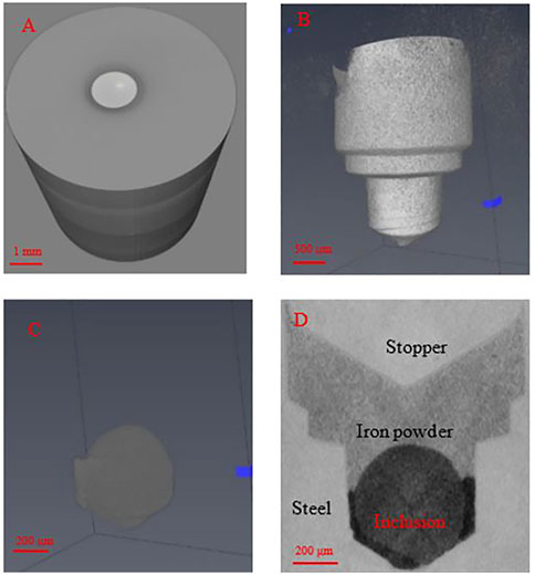
FIGURE 4. CT scans of samples. (A) Whole pellet, stopper can be seen. (B) Removing the steel matrix, the stopper with the inclusion and iron powder. (C) Inclusion and iron powder with the inclusion being the round part. (D) Ortho slice of sample.
Combining the use of HT-CLSM and XCT allows for a fully immersed inclusion in liquid steel to be located in the quenched sample. Two different heating regimes were used to test the pellet samples to study the liquid-liquid interactions where both the steel and the inclusion are liquid.
The slow heating regime was designed to minimise the risk of the inclusion floating. The sample was heated to 1673 K at a rate of 473 K per minute then slowly heated to 1823 K at a rate of 323 K per minute and held for a time of 5–10 min then cooled at a rate of 573 K per minute to room temperature. At this temperature, the inclusion would be liquid and the steel would be in a mushy zone which could prevent the inclusion from floating.
The fast heating regime was designed to allow for the sample to be fully molten (steel and inclusion) but only for short times to reduce risk of the inclusion floating out of the sample. The sample was quickly heated to 1873 K at a heating rate of 500 K per minute and held for a period of time from 0 to 20 s. The sample was then quickly quenched at a rate of 1500 K per minute from 1893 to 973 K and then cooled further at a rate of 300 K per minute to room temperature.
With the slow heating regime, the steel did not melt completely as the lines of the stopper can be seen in Figure 5. The slow heating regime is more difficult to obtain a kinetic study as it does not give a time resolution as the time when the steel melted is unknown. The red particles are the inclusion, and the blue is the porosity. The inclusion did not change composition in these samples.
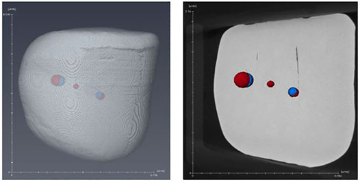
FIGURE 5. showing a sample melted with the slow heating regime.
Based on the results from the slow heating regime, a fast-heating regime has been developed where the samples were superheated and quenched quickly. The XCT scans shown in Figure 6 show the sample with the inclusion embedded in the steel matrix. Full melting of the sample was confirmed by XCT as the presence of a stopper was not seen.
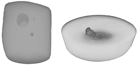
FIGURE 6. Two 3D XCT scans of a fast heated sample showing the inclusion within the steel matrix.
For the slow heating regime, it was difficult to ensure whether the steel had melted completely or not. It did mean that the inclusion did remain in the steel sample and the risk of it floating out was minimised, however a time resolution for the reaction was difficult to be determined. This is an advantage of the fast-heating regime. As the sample was quickly heated to 1873 K a time resolution could be calculated as it was visible when the steel had melted by in-situ observation as well as XCT scans showing no presence of a steel stopper showing the steel had completely melted. A disadvantage of the fast-heating regime was that the inclusion floats so the experiment could not be run for longer than 20 s at peak temperature as the inclusion floats to the surface and the reaction is compromised as the inclusion is no longer full entrained in the steel. This experimental method had a very low success rate of retention of inclusions in the sample, but if tests were successful, the reaction kinetics could be calculated from post-test analysis for the inclusion and steel compositions after sectioning the sample. The inserted starting inclusion composition had a silica content of 42.1 wt. % and an alumina content of 7.4 wt. %. For testing using the steel containing 1 wt% Al after 20 s, the silica content reduced to 2.8 wt. % and the alumina content increased to 46.8 wt. %. The fast-heating regime also allowed for the morphology of an inclusion to be investigated during the reaction from the interrupted tests (shorter duration at peak temperature then quenched). This test method provided unique information on the inclusion-steel reaction behaviour, where it was observed that the inclusion’s surface area increased by a factor of 13 times its original size when the reaction occurred due to spontaneous emulsification occurring. Further information on this phenomena can be found in our published work (Raviraj et al., 2021).
This aim of this test method development was to explore reactions between an inclusion and steel at high temperature under conditions when the steel and/or inclusion are molten and the resulting compositional changes. An additional aim was to minimise the time required for testing and unsuccessful tests (as seen for the above experiments where XCT is required and inclusion floatation occurred).
The steel provided by Tata Steel Europe was cut to 5 mm edge length cubes using EDM and a pilot drill was used to indent the sample to a depth of 0.5 mm with a diameter of 0.5 mm for the placement of an inclusion on the surface as shown in Figure 7.
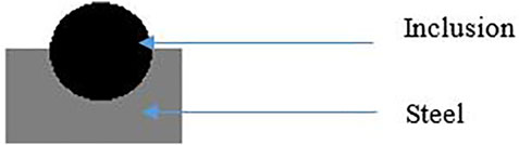
FIGURE 7. Schematic of dimple sample.
A combination of HT-CLSM and SEM/EDS techniques was used for this experimental procedure. The sample was preheated to 473 K, using a slow heating rate (to ensure the longevity of the halogen lamp) prior to being heated and quenched quickly with a heating regime of 500 K per minute from 473K to 1473 K for the first test (liquid inclusion (melting temperature 1400 K)–solid steel), and 1873 K (liquid inclusion–liquid steel (melting temperature of 1873 K)) for the second test. The tests were held for a period of time ranging from 0–1800 s. The sample was then quenched at a rate of 1500 K per minute from 1473 to 973 K and then cooled further at a rate of 300 K per minute to room temperature. The steel was determined to be liquid when the area surround the inclusion was molten through in-situ observations via the HT-CLSM. This could not be done for longer than 20 s as the interface between the steel and inclusion would disappear due to the steel becoming completely molten. Therefore, the steel was used to be in a semi-solid state as the steel surrounding the inclusion was molten whilst the rest of the steel was solid.
Figures 8, 9 are two examples of the test outputs for reaction between an inclusion and 1wt% Al steel using SEM for post test examination with the corresponding composition analysis of aluminium and silicon given in Table 4; Table 5. As it can be seen, in Figure 8 the indent where the inclusion has been placed still has the same shape indicating that only the inclusion has melted at 1473 K as expected. In Figure 9 at 1873 K the shape of the indent has changed showing that the steel around the inclusion has melted. The composition of the inclusion and the steel has not changed after 60 s at 1473 K as shown in Table 4, however the composition of the inclusion has changed after 5 s at 1873 K as shown in Table 5.
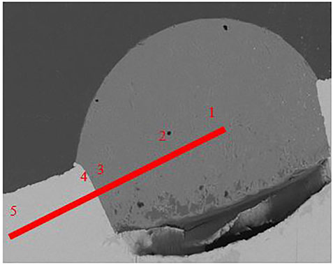
FIGURE 8. SEM image of the 60 s sample at 1473 K with the point analysis showing the composition of Al and Si.
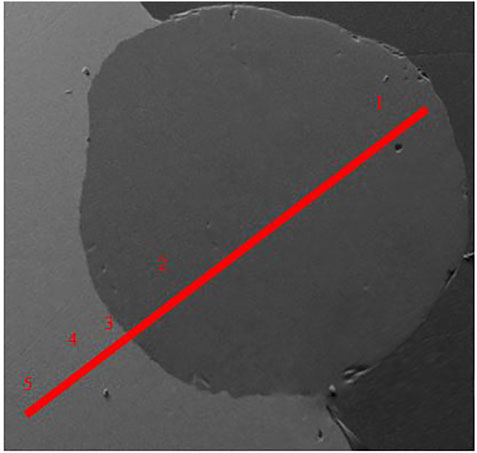
FIGURE 9. SEM image of the 5 s sample at 1873 K with the point analysis showing the composition of Al and Si.
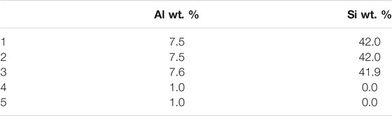
TABLE 4. Compositions of alumina and silica across the line scan.
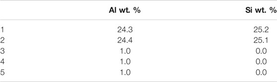
TABLE 5. Compositions of alumina and silica across the line scan.
Figure 10 shows two images taken from the video from the HT-CSLM. A ring appears around the inclusion at 1,200°C–700°C when cooling the sample indicating there might be a phase change in the steel from austenite to ferrite. This could be due to an increase in oxygen around the area of the inclusion as there could be an oxygen ingress from the gas atmosphere or due to the reaction with the inclusion which could be further evidence of reaction kinetics occurring when the sample is heating up. This could compromise actual industrial scenarios where inclusions get swept into the liquid steel.
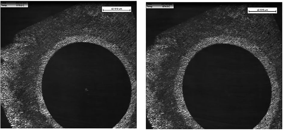
FIGURE 10. Images from the confocal laser scanning microscope video at two different time points showing a ring appear around the inclusion.
The successes of this test method are that different reaction rates can be investigated with different temperatures as at 1473 K there is no change in the compositions of the steel whereas after 5 s there is a significant change in the composition of the inclusion at 1873 K. Melting the steel around the inclusion is quite difficult as there is a small window of 20 s before the steel melts completely. Another advantage of this test method is that the inclusion embedded into the steel surface can be carefully monitored to see if it has melted or not as well as any interactions with the surrounding steel for example, the phase changes when the temperature increases.
The various test methods have allowed detailed investigation into the reaction between a high aluminium steel and an inclusion with the chemical any physical changes and their implications discussed elsewhere in the literature (Raviraj et al., 2021). Each test method has its own advantages and disadvantages as shown in Table 6 and summarised below.
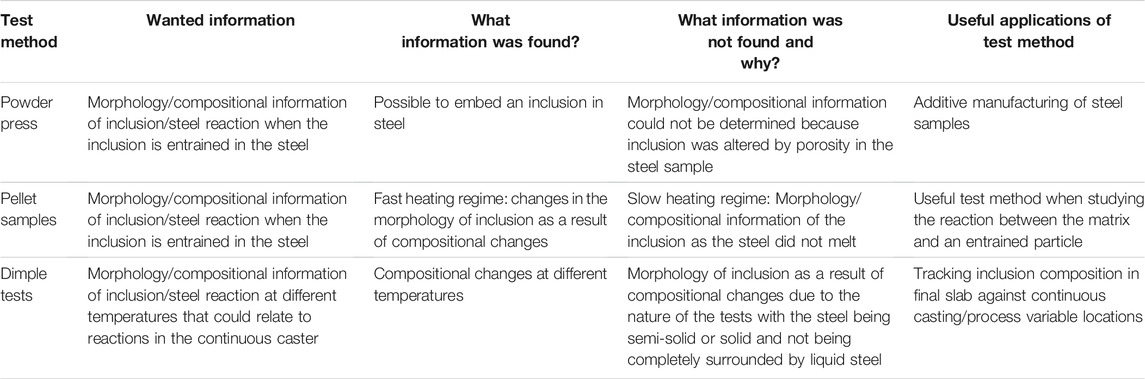
TABLE 6. Comparison between all the test methods showing the applications, information needed and information that was found and not found.
The powder press samples showed the ability to embed an inclusion and the capabilities of using sintered steel to create a sample for this study. The powder press pellets are not appropriate for this study due to influence of porosity on the inclusion morphological changes during heating when the inclusion becomes molten, and the location of the inclusion to begin with, however could be important for studies relevant to other processes such as powder 3D printing.
The pellets with an inclusion are suitable to replicate industrial conditions as close as possible with an inclusion completely surrounded by molten steel. The pellet samples were useful when studying the reaction between the matrix and an entrained particle giving valuable information about the morphology changes of the inclusion as well as chemical compositions of the inclusion and surrounding steel. The limitation is the length of time the high temperature reaction can be evaluated for because of the limited size of the sample being tested and flotation rate of the inclusion. Previous work on the reaction between high aluminum steel and a silica rich slag (Park et al., 2013; Park et al., 2014a; Park et al., 2014b) has suggested that the kinetics follow a first-order relationship with aluminum diffusion being the rate controlling step through mass transfer in the metal phase (Park et al., 2013; Park et al., 2014b)
The dimple samples allow for different temperature conditions to be investigated to calculate a rate of reaction under different conditions (molten steel and / or inclusion). The dimple tests also gave kinetic data for potentially tracking inclusion composition changes under the different conditions. The dimple tests showed that a reaction does take place when the inclusion is liquid and the steel is semi-solid with the silica content decreasing to 35% of its starting composition after 20 s. The reaction was still ongoing but difficult to capture due to the steel becoming fully molten after 20 s. It did however allow the inclusion to be investigated when in contact with a liquid steel layer with solid steel.
When casting high aluminium steels, the effect of the mould flux needs to be taken into consideration. The results from this research have shown what the reaction times are and what floatation times are and this could aid in deciding which casting route is appropriate. The ability to employ a correlative study across these different experimental techniques and test methods offers the potential to innovatively understand inclusion behaviour in a highly unpredictable and chemically unstable system.
The main objectives of this paper were to determine a suitable experimental technique to investigate the reaction between silica in the inclusion and aluminium in the steel. Through an innovative application of advanced laboratory techniques, different test methods allowed for different aspects of the reaction and interaction between silica and aluminium to be investigated. The powder press samples showed the ability to embed an inclusion and the capabilities of using sintered steel to create a sample for this study. The pellet samples were useful when studying the reaction between the matrix and an entrained particle giving valuable information about the physical morphologies as well as chemical compositions. The dimple tests also gave kinetic data for potentially tracking inclusion compositions in the final slab against continuous casting processes and variable locations. The above work provides a deeper understanding into the importance of mould flux design for high aluminium steels. Silica is an important component in mould fluxes due to its high viscosity and crystallisation properties and if silica were to be replaced for casting high aluminium steels, these properties still need to be maintained without a reaction taking place between the mould powder and the aluminium.
The raw data supporting the conclusions of this article will be made available by the authors, without undue reservation.
SSp, SSr, CD, and MW are the academic supervisors WT and GA are the industrial supervisors JL is a research fellow that was involved in the project NK and JW were involved with the XCT scanning of the samples AR is the EngD student who completed the research.
The research was funded by EPSRC and Tata Steel Europe.
Authors GA and WT were employed by the company Tata Steel.
The remaining authors declare that the research was conducted in the absence of any commercial or financial relationships that could be construed as a potential conflict of interest.
All claims expressed in this article are solely those of the authors and do not necessarily represent those of their affiliated organizations, or those of the publisher, the editors and the reviewers. Any product that may be evaluated in this article, or claim that may be made by its manufacturer, is not guaranteed or endorsed by the publisher.
I would like to thank EPSRC and Tata Steel Europe for funding this research via the EngD scheme, to WMG for the provision of facilities and to Tata Steel Europe for providing the samples used in this study.
Assis, A. N., Warnett, J., Spooner, S., Fruehan, R. J., Williams, M. A., and Sridhar, S. (2015). Spontaneous Emulsification of a Metal Drop Immersed in Slag Due to Dephosphorization: Surface Area Quantification. Metall. Materi Trans. B 46, 568–576. doi:10.1007/s11663-014-0248-z
Bastien, P. (1977). The Possibilities and Limitations of Ultrasonics in the Non-destructive Testing of Steel. NDT Int. 10, 297–305. doi:10.1016/0308-9126(77)90003-7
Eckel, J. A., Glaws, P. C., Wolfe, J. O., and Zorc, B. J. (1998). “Clean Engineered Steels - Progress at the End of the Twentieth century,” in Symposium on Advances in the Production and Use Steel with Improved Internal Cleanliness 1–11, Atlanta, GA, April 5, 1998 (ASTM Special Technical Publication).
Lopez, P. E. R., Jalali, P. N., Björkvall, J., Sjöström, U., and Nilsson, C. (2014). Recent Developments of a Numerical Model for Continuous Casting of Steel: Model Theory, Setup and Comparison to Physical Modelling with Liquid Metal. ISIJ Int. 54, 342–350. doi:10.2355/isijinternational.54.342
Park, J., Sridhar, S., and Fruehan, R. J. (2013). Activity Coefficient of SiO2 in SiO2-Al2O3-CaO Slags with Low SiO2-Content at 1873 K (1600 °C). Metall. Materi Trans. B 44, 13–15. doi:10.1007/s11663-012-9786-4
Park, J., Sridhar, S., and Fruehan, R. J. (2014). Kinetics of Reduction of SiO2 in SiO2-Al2O3-CaO Slags by Al in Fe-Al(-Si) Melts. Metall. Materi Trans. B 45, 1380–1388. doi:10.1007/s11663-014-0076-1
Park, J., Sridhar, S., and Fruehan, R. J. (2014). Ladle and Continuous Casting Process Models for Reduction of SiO2 in SiO2-Al2O3-CaO Slags by Al in Fe-Al(-Si) Melts. Metall. Materi Trans. B 46, 109–118. doi:10.1007/s11663-014-0199-4
Pretorius, E. B., Oltmann, H. G., and Schart, B. T. (2015). An Overview of Steel Cleanliness from an Industry Perspective. Iron Steel Techn. 12 (3), 333–345.
Raviraj, A., Kourra, N., Williams, M. A., Abbel, G., Davis, C., Tiekink, W., et al. (2021). The Spontaneous Emulsification of Entrained Inclusions during Casting of High Aluminum Steels. Metall. Mater. Trans. B 52, 1154–1163. doi:10.1007/s11663-021-02091-z
Ren, Y., Wang, Y., Li, S., Zhang, L., Zuo, X., Lekakh, S. N., et al. (2014). Detection of Non-metallic Inclusions in Steel Continuous Casting Billets. Metall. Materi Trans. B 45, 1291–1303. doi:10.1007/s11663-014-0042-y
Wells, J. M. (2007). “Quantitative XCT Evaluation of Porosity in an Aluminum alloy Casting,” in Proc. 2nd Int. Symp. On Shape Casting. Editors P. N. Crepeau, M. Tiryakioglu, and J. Campbell (TMS), 77–84.
Zhang, L., and Thomas, B. G. (2003). “Inclusions in Continuous Casting of Steel,” in Proceedings of the XXIV National Steelmaking Symposium, PG, 138–183.
Zhang, L., Thomas, B. G., Wang, X., and Cai, K. (2002). Evaluation and Control of Steel Cleanliness: Review. Warrendale,PA: 85th Steelmak. Conf. ISS-AIME, 431–452.
Zhang, X., Zhang, L., Yang, W., Wang, Y., Liu, Y., and Dong, Y. (2017). Characterization of the Three-Dimensional Morphology and Formation Mechanism of Inclusions in Linepipe Steels. Metall. Materi Trans. B 48, 701–712. doi:10.1007/s11663-016-0833-4
Keywords: inclusion, high aluminium steel, reaction kinetics, continuous casting, spontaneous emulsification
Citation: Raviraj A, Spooner S, Li J, Kourra N, Warnett J, Abbel G, Tiekink W, Williams MA, Davis C and Sridhar S (2021) Artificial Inclusion Environments—Replicating Industry in the Laboratory. Front. Mater. 8:754284. doi: 10.3389/fmats.2021.754284
Received: 06 August 2021; Accepted: 28 September 2021;
Published: 10 November 2021.
Edited by:
Susanne K. Michelic, University of Leoben, AustriaReviewed by:
Heng Cui, University of Science and Technology Beijing, ChinaCopyright © 2021 Raviraj, Spooner, Li, Kourra, Warnett, Abbel, Tiekink, Williams, Davis and Sridhar. This is an open-access article distributed under the terms of the Creative Commons Attribution License (CC BY). The use, distribution or reproduction in other forums is permitted, provided the original author(s) and the copyright owner(s) are credited and that the original publication in this journal is cited, in accordance with accepted academic practice. No use, distribution or reproduction is permitted which does not comply with these terms.
*Correspondence: A. Raviraj, YS5yYXZpcmFqQHdhcndpY2suYWMudWs=
Disclaimer: All claims expressed in this article are solely those of the authors and do not necessarily represent those of their affiliated organizations, or those of the publisher, the editors and the reviewers. Any product that may be evaluated in this article or claim that may be made by its manufacturer is not guaranteed or endorsed by the publisher.
Research integrity at Frontiers
Learn more about the work of our research integrity team to safeguard the quality of each article we publish.