 Jun Yang
 Junjie Xu1
 Guangsheng Deng
95% of researchers rate our articles as excellent or good
Learn more about the work of our research integrity team to safeguard the quality of each article we publish.
Find out more
ORIGINAL RESEARCH article
Front. Mater. , 13 August 2021
Sec. Metamaterials
Volume 8 - 2021 | https://doi.org/10.3389/fmats.2021.723851
This article is part of the Research Topic Electromagnetic Metamaterials and Metasurfaces View all 7 articles
In this paper, we present a novel design of an electrically tunable metamaterial device in the terahertz frequency range of 325–500 GHz. The device is analyzed and optimized using an equivalent circuit and numerical simulation. The experimental and simulation results are almost identical in the entire design frequency range. A maximum modulation depth of 90.87% is achieved in the transmission window. The bandpass width decreases from 102.55 to 28.7 GHz as the bias voltage increases from 0 to 30 V. This structure provides new insights into the potential of electrically tunable terahertz devices for a wide range of applications.
Terahertz (THz) waves have shown great potential in the fields of high-speed wireless communication, biomedical imaging and sensor because of their many unique characteristics (Nagatsuma et al., 2016; Luo et al., 2019). In these fields, THz modulators (Jafari et al., 2020), switches (Yang et al., 2020), and filters (Ahamed et al., 2021) are the key components in the development of THz communication, imaging and spectroscopy systems. Various materials with tunable characteristics such as graphene and vanadium dioxide have been used to actively control the THz waves (Park et al., 2018). Nematic liquid crystal is an anisotropic material whose rod-like molecules can be arranged in an orderly manner by applying an electric or magnetic field. It shows high birefringence characteristics when the molecules rotate under excitation (Wang et al., 2019). For the nematic liquid crystal device, the response time is composed of the rise time and the decay time. The rotation time can be greatly cut down by applying a large bias voltage (Yin et al., 2018). Compared with other tunable materials, the liquid crystal (LC) is continuously adjustable with lower operating voltage, low-cost and easy to fabricate large arrays.
Artificial metamaterials can amplify the tuning performance of liquid crystal, thereby achieving a dynamic control of the THz waves (Fu and Cui, 2019; Shen et al., 2020). Recently, many tunable THz devices based on the metamaterials have been reported. For example, a superconducting THz electrical modulator based on the metamaterials was proposed by Li et al. (Li et al., 2017). The maximum modulation depth of the device in the transmission window reached 79.8%. Controlled by an electrical sinusoidal signal, such a device could achieve a modulation speed of approximately 1 MHz. In addition, Ge et al. proposed a pseudo Fabry–Pérot filter (Ge et al., 2015). Separate sharp resonant peaks were shown in the simulated transmission spectra, whose positions shifted toward higher frequencies when the refractive index of liquid crystal decreased. Tunable metasurface incorporated with active components can achieve active anisotropy, providing a new platform to dynamically manipulate electromagnetic wave (Chen et al., 2020).
In this paper, we propose a double-layer plasmonic metamaterial composed of symmetric trapezoidal slotted unit cells to demonstrate the transmission characteristics of LC-based metamaterial. The metal array controls the transmission frequency of the THz waves. Surface plasmons (SPs) can be excited when the structure period matches the incident THz wave frequency (Zhang et al., 2018). Equivalent circuit modeling is built to provide a clear electromagnetic understanding. The Finite Element Method (FEM) is used to calculate and optimize the structural parameters to achieve the most optimal performance. The proposed design exploits the voltage-dependent anisotropy of the liquid crystal to achieve good modulation and filtering characteristics.
Figure 1A shows that the single unit cell of the LC-based design is symmetrical in the three coordinate directions. The upper and lower copper layers are immersed in the liquid crystal layer, and two parallel quartz glass substrates play a supporting role. The reorientation of liquid crystal molecules is controlled by spin-coating two polyimide alignment layers on the copper layer. The long axis of the liquid crystal molecules is aligned along the x-axis when there is no bias voltage. The unit cell of the metamaterial structure consists of four trapezoidal slotted structures symmetrical to one another as shown in Figure 1B. The copper layers are also used as an electrode in order to apply a bias voltage to the liquid crystal. When a saturated bias voltage is applied, the long axis of the molecules is aligned parallel to the direction of the applied electric field, which increases the dielectric constant of the liquid crystal.
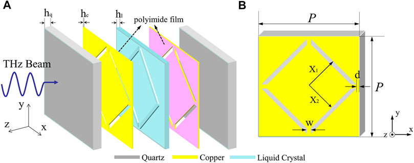
FIGURE 1. (A) Cross-section schematic diagram of the unit cell. hq = 300 µm, hc = 0.5 µm, hl = 45 µm. (B) Copper layer of the unit cell formed on the quartz surface. X1 = 122 µm, X2 = 108 µm, W = 14 µm, P = 350 µm.
When the THz waves are incident normally onto the device, they are modulated by the plasmonic metamaterial that acts as a resonant circuit, as shown in Figure 2A. The inductance L is mainly determined by the width (w) between the hypotenuse of two trapezoidal slots and the width (d) between the slot and square border. The capacitance (C) is a function of the altitude (X1-X2) and the bases of the trapezoidal slot. In order to clearly analyze the resonant structure, an equivalent model consisting of two parallel branches is developed to describe the frequency response of the entire structure, as shown in Figure 2B. The parallel circuit represents the resonance characteristics of the metallic layer, while the liquid crystal layer acts as a variable interlayer capacitance (Cin). The resistance Rs is used to calculate the ohmic loss of metamaterials which caused the transmission loss.
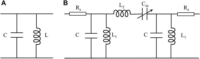
FIGURE 2. (A) Parallel equivalent circuit model of the copper pattern. (B) Equivalent circuit model of an array composed of the unit cell.
The transmission characteristics of the device are calculated using the finite element method (FEM). The conductivity of copper is set to 5.8 × 10⁷ S/m. The dielectric constant and loss tangent of quartz are εQL = 3.78 and tan (δQL) = 0.002, respectively. In addition, the characteristic parameters of the liquid crystal are as follows: ε⊥ = 2.547, tan (δ⊥) = 0.02, ε∥ = 3.65 and tan (δ∥) = 0.02. The incident THz wave is a linearly polarized normal plane wave with a frequency range between 325 and 500 GHz. Figure 3 shows the electromagnetic simulation results. The transmittance of the device is 81.2% at 415.5 GHz when the dielectric constant of the liquid crystal layer is set to 2.547. In order to depict the filtering characteristics of the device, the bandpass width is defined as the range of frequency between two points, at which point the transmittance is 70%. The bandpass width is 90.3 GHz when there is no bias voltage. As the dielectric constant of the LC increases from 2.547 to 3.65, the transmittance of the device drops to 7.6% at 415.5 GHz and the bandpass width drops to 39.2 GHz. Furthermore, the center frequency is shifted from 388.35 GHz to 346.18 GHz as the dielectric constant of the liquid crystal increases from 2.547 to 3.65. Modulation depth (MD) are important parameters for judging the modulation capability of a device. They can be calculated as follows for the proposed design:
In the above expressions, Tmax and Tmin represent the maximum and minimum transmittance of the device at a certain frequency, respectively. The amplitudes of modulation depth are calculated as 90.7% using (1).
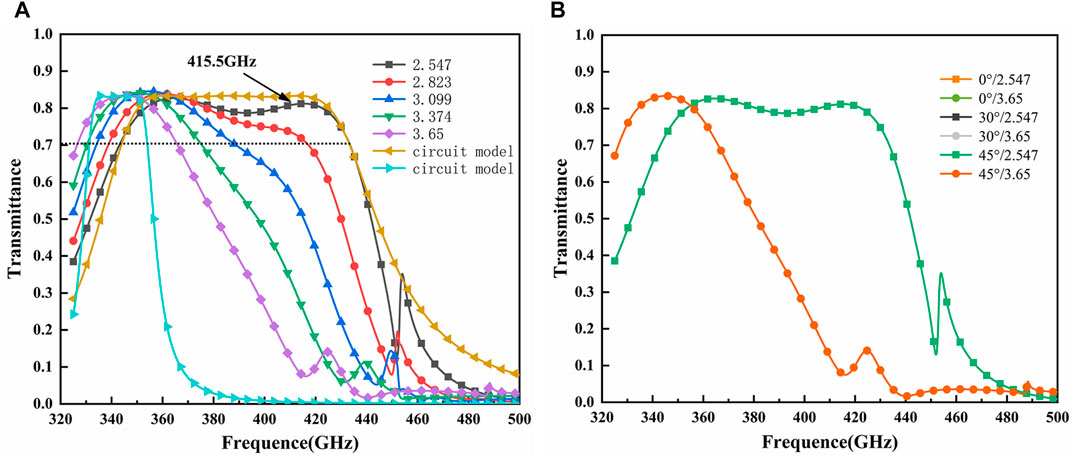
FIGURE 3. (A) Simulation of transmission spectra at different dielectric constants of liquid crystal and transmission characteristics of the equivalent model. (B) Simulation of transmission characteristics at different polarization angles.
When the component parameters of the circuit are as follows: L1 = 5.10 pH, L2 = 166.52 pH, C = 0.0333 pF, Cin = 0.00102 pF, Rs = 10 Ω, and the dielectric constant of the liquid crystal is set to 2.547, the transmission characteristics of the equivalent circuit are similar to the simulation results obtained using the FEM, as shown in Figure 3A. When the component parameters change to: L1 = 1.65 pH, L2 = 654.26 pH, C = 0.1385 pF, Cin = 0.00033 pF, and the dielectric constant of the liquid crystal is set to 3.65, the resonant frequency of the equivalent circuit is consistent with the simulation results. The electromagnetic waves can be enhanced when the incident frequency is consistent with the resonant frequency of the equivalent circuit, and the incident waves outside the resonant frequency range are blocked. The transmission characteristics of the device at different polarization angles are obtained by calculating the transmittance for polarization angles ranging from 0 to 45°, as shown in Figure 3B. The transmission characteristics under different polarization angles are consistent, which proves the polarization independence.
The surface current distribution and the electric field distribution at the frequency of the maximum modulation depth is calculated respectively to reveal the intrinsic physical mechanism of the proposed design, as shown in Figure 4. Figures 4A,D show the electric field distribution in the device. The transmittance of THz waves while unbiased is greater than that while biased. When an electromagnetic wave is normally incident to the device, surface plasmons (SPs) coupling is excited by double-layer metamaterial, and the energy of the coupled field is mainly concentrated in the dielectric layer (Barnes et al., 2003). Figures 4B,C show the surface current distribution on the metamaterial surface while unbiased and biased. When the SPs are excited on the surface of the upper copper layer, the surface current is mainly concentrated on the edges of the four trapezoidal slotted structures and flows parallel to the polarization direction of the incident wave. The liquid crystal layer is kept very thin to ensure that the SPs can effectively propagate to the lower layer, and then transformed into free-space electromagnetic waves through coupling. The energy of the electromagnetic field is mainly concentrated in the liquid crystal layer. Due to the monotonic relationship between the dielectric constant and the transmission characteristics, the THz beam can be controlled flexibly and effectively by applying different bias voltages over the design frequency range.
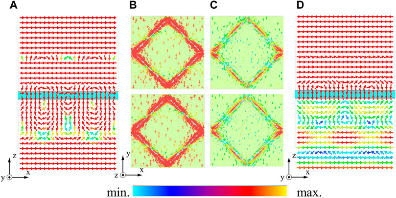
FIGURE 4. Electric field and surface current distributions at 415.5 GHz while biased and unbiased. (A) Electric field distribution while unbiased. (B) Surface current distribution of the upper and lower copper layers of the unit cell while unbiased. (C) Surface current distribution of the upper and lower copper layers of the unit cell while biased. (D) Electric field distribution while biased.
Figure 5A shows the proposed tunable device with 40 × 40 unit cell of sub-wavelength trapezoidal air slots that was fabricated using an ultraviolet lithography process. The array is printed on a 20 × 20 mm area of a 0.3 mm thick quartz substrate with a thickness tolerance of ±5 μm. The length and width tolerance of air slots is within the limits of ±3 μm compared with the design values. The four crosses structure at the sample edges are used for the alignment of two metamaterial layers. The electrode is used to load external biased voltage. The device is tested using the measurement system as shown in Figure 5B. The vector network analyzer is used to test the spectral response of the sample and the mm-wave module extender is used to adjust the incident frequency range to 325–500 GHz. The bias voltage is an amplified 1 kHz square wave signal provided by the signal generator to prevent electric charge from accumulating in the sample.
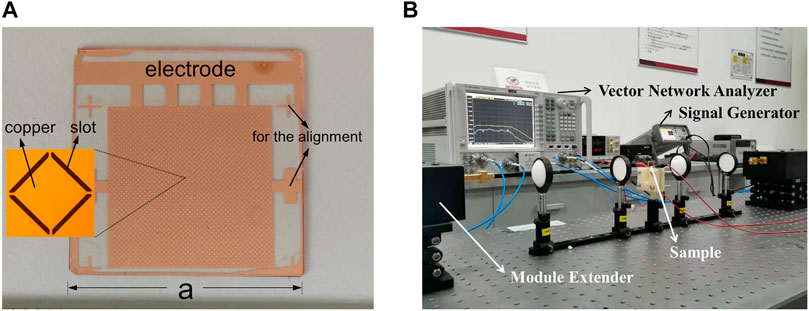
FIGURE 5. (A) Copper pattern on a quartz substrate and microscopic image of a unit cell. The square area is an array composed of 30 × 30 unit cells, which is connected to an electrode. a = 2 cm. (B) Test equipment and environment. The lens was used to focus the incident THz beam.
Figure 6 shows the transmission spectra of the sample under different bias voltages. When the bias voltage is 0V, the device has a fairly flat transmission in the passband. As the applied bias voltage increases from 0 V to 30 V, the transmission peak on the left shifts from 359.65 to 341.63 GHz. Meanwhile, the transmission peak on the right reduces gradually. The bandpass width decreases from 102.55 to 28.7 GHz as shown in Figure 7A. Figure 7B shows the modulation depth of the sample under different bias voltages at 409 GHz. As the applied bias voltage reaches saturation, the maximum modulation depth becomes 90.87%. The transmittance gradually decreases from 83.35 to 7.6% at the resonance frequency of 409 GHz. The size of fabricated array is still not large enough to approximate to infinite periodicity boundary. The test results include direct transmission of energy, which is not through the sample. The modulation depth is almost a constant when the applied bias voltage is less than 1 V, which is the threshold voltage required for the reorientation of liquid crystal molecules. When the bias voltage is less than 6 V, the device's response to voltage variation is more sensitive than that between 6–30 V because the liquid crystal molecules can rotate easily in the beginning. After reaching 15 V, the voltage does not significantly affect the device.
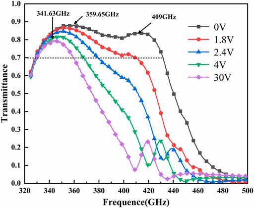
FIGURE 6. Transmission spectra of the sample at different bias voltages.
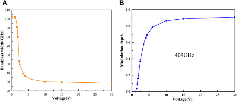
FIGURE 7. (A) Bandpass width under different bias voltages. (B) Amplitude modulation under different bias voltages.
The experimental results have difference with the simulation results. The frequency point of the optimal modulation depth observed in the measurement is shifted to the left by 6.5 GHz compared with the simulation results, which may be caused by dimensional manufacturing. Insufficient etching may reduce the altitude (X1-X2) of the trapezoidal slot. The transmission peak on the right redshifts to the low frequency with the decrease of altitude as shown in Figure 8. However, the evolution of the spectrum in the incident frequency range is consistent with the theoretical analysis results.
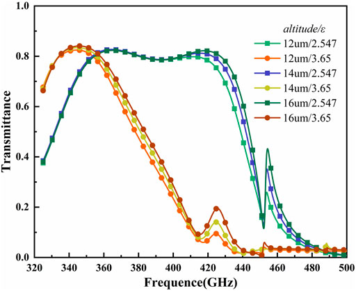
FIGURE 8. Simulation of transmission spectra of the device at different trapezoidal slot altitude.
This paper investigated the transmission characteristics of a tunable THz device based on metamaterial and liquid crystal. The tunable device was designed, fabricated and tested. The thin liquid crystal layer was used to dynamically modulate the frequency of the THz beam that could excite the SPs. The equivalent circuit was used to describe the expected frequency response of the device. Transmittance spectra of the sample showed that the maximum modulation depth was 90.87% at 409 GHz. In addition, the bandpass width decreased from 102.55 to 28.7 GHz. The electrically tunable device can replace multiple components and provide a potential solution for the THz system.
The raw data supporting the conclusions of this article will be made available by the authors, without undue reservation.
JY, and JX executed the experiment and wrote the manuscript. FC planned and supervised the whole study. RM, YL analyzed the experimental results. ZY, GD advised on numerical calculation and analysis.
This work was supported by the Opening Project of Guangxi Key Laboratory of Wireless Wideband Communication and Signal Processing under Grant GXKL06200207, and National Natural Science Foundation of China (No.61871171).
The authors declare that the research was conducted in the absence of any commercial or financial relationships that could be construed as a potential conflict of interest.
All claims expressed in this article are solely those of the authors and do not necessarily represent those of their affiliated organizations, or those of the publisher, the editors and the reviewers. Any product that may be evaluated in this article, or claim that may be made by its manufacturer, is not guaranteed or endorsed by the publisher.
Ahamed, E., Tamim, A. M., Faruque, M. R. I., Sifat, R., and Islam, M. T. (2021). Reconfigurable THz Metamaterial Filter Based on Binary Response for Information Processing System. Front. Phys. 9, 661060. doi:10.3389/fphy.2021.661060
Barnes, W. L., Dereux, A., and Ebbesen, T. W. (2003). Surface Plasmon Subwavelength Optics. Nature 424, 824–830. doi:10.1038/nature01937
Chen, K., Zhang, N., Ding, G., Zhao, J., Jiang, T., and Feng, Y. (2020). Active Anisotropic Coding Metasurface with Independent Real‐Time Reconfigurability for Dual Polarized Waves. Adv. Mater. Technol. 5, 1900930. doi:10.1002/admt.201900930
Fu, X., and Cui, T. J. (2019). Recent Progress on Metamaterials: From Effective Medium Model to Real-Time Information Processing System. Prog. Quan. Electron. 67, 100223. doi:10.1016/j.pquantelec.2019.05.001
Ge, S. J., Liu, J. C., Chen, P., Hu, W., and Lu, Y. Q. (2015). Tunable Terahertz Filter Based on Alternative Liquid crystal Layers and Metallic Slats. Chin. Opt. Lett. 13, 4. doi:10.3788/col201513.120401
Jafari, B., Soofi, H., and Abbasian, K. (2020). Low Voltage, High Modulation Depth Graphene THz Modulator Employing Fabry-Perot Resonance in a Metal/dielectric/graphene sandwich Structure. Opt. Commun. 472, 125911. doi:10.1016/j.optcom.2020.125911
Li, C., Wu, J., Jiang, S., Su, R., Zhang, C., Jiang, C., et al. (2017). Electrical Dynamic Modulation of THz Radiation Based on Superconducting Metamaterials. Appl. Phys. Lett. 111, 092601. doi:10.1063/1.4997097
Luo, C.-G., Deng, B., Wang, H.-Q., and Qin, Y.-L. (2019). High-resolution Terahertz Coded-Aperture Imaging for Near-Field Three-Dimensional Target. Appl. Opt. 58, 3293–3300. doi:10.1364/ao.58.003293
Nagatsuma, T., Ducournau, G., and Renaud, C. C. (2016). Advances in Terahertz Communications Accelerated by Photonics. Nat. Photon 10, 371–379. doi:10.1038/nphoton.2016.65
Park, D. J., Shin, J. H., Park, K. H., and Ryu, H. C. (2018). Electrically Controllable THz Asymmetric Split-Loop Resonator with an Outer Square Loop Based on VO2. Opt. Express 26, 17397–17406. doi:10.1364/oe.26.017397
Shen, Z., Zhou, S., Li, X., Ge, S., Chen, P., Hu, W., et al. (2020). Liquid crystal Integrated Metalens with Tunable Chromatic Aberration. Adv. Photon. 2, 1. doi:10.1117/1.Ap.2.3.036002
Wang, L., Xiao, R.-W., Ge, S.-J., Shen, Z.-X., Lü, P., Hu, W., et al. (2019). Research Progress of Terahertz Liquid crystal Materials and Devices. wlxb 68, 084205. doi:10.7498/aps.68.20182275
Yang, J., Gao, S., Wang, P., Yin, Z., Lu, H., Lai, W., et al. (2020). Design and Experimental Verification of a Liquid Crystal-Based Terahertz Phase Shifter for Reconfigurable Reflectarrays. J. Infrared Milli Terahz Waves 41, 665–674. doi:10.1007/s10762-020-00705-2
Yin, Z., Wan, C., Deng, G., Zheng, A., Wang, P., Yang, Y., et al. (2018). Fast-Tunable Terahertz Metamaterial Absorber Based on Polymer Network Liquid Crystal. Appl. Sci. 8, 2454. doi:10.3390/app8122454
Keywords: terahertz, metamaterial, liquid crystals, transmission characteristics, surface plasmons, resonant circuit
Citation: Yang J, Xu J, Mao R, Li Y, Yin Z, Deng G and Cai F (2021) Terahertz Transmission Characteristics of Double-Layer Plasmonic Metamaterial and LC-Based Structure. Front. Mater. 8:723851. doi: 10.3389/fmats.2021.723851
Received: 11 June 2021; Accepted: 04 August 2021;
Published: 13 August 2021.
Edited by:
Wei-Xiang Jiang, Southeast University, ChinaCopyright © 2021 Yang, Xu, Mao, Li, Yin, Deng and Cai. This is an open-access article distributed under the terms of the Creative Commons Attribution License (CC BY). The use, distribution or reproduction in other forums is permitted, provided the original author(s) and the copyright owner(s) are credited and that the original publication in this journal is cited, in accordance with accepted academic practice. No use, distribution or reproduction is permitted which does not comply with these terms.
*Correspondence: Fei Cai, Y2FpZmVpQGhmdXQuZWR1LmNu
Disclaimer: All claims expressed in this article are solely those of the authors and do not necessarily represent those of their affiliated organizations, or those of the publisher, the editors and the reviewers. Any product that may be evaluated in this article or claim that may be made by its manufacturer is not guaranteed or endorsed by the publisher.
Research integrity at Frontiers
Learn more about the work of our research integrity team to safeguard the quality of each article we publish.