 Baokui Chen
 Bao Jia
 Ming Wen*
94% of researchers rate our articles as excellent or good
Learn more about the work of our research integrity team to safeguard the quality of each article we publish.
Find out more
ORIGINAL RESEARCH article
Front. Mater. , 13 August 2021
Sec. Structural Materials
Volume 8 - 2021 | https://doi.org/10.3389/fmats.2021.722018
This article is part of the Research Topic Advanced Sensing, Materials and Intelligent Algorithms for Multi-Domain Structural Health Monitoring View all 23 articles
Purlin roof structure houses, which have the advantages of readily accessible materials and simple construction, are widely used in rural areas of China. However, during earthquakes, the wooden purlins tend to fall off and the walls crack. Therefore, it is necessary to monitor the structural parameters of and strengthen the anti-seismic capacity of these structures. To compensate for the seismic deficiencies of the purlin roof structure, a novel damping-limit device installed at the connection position of the gable and the wooden purlin was proposed. In this study, the seismic performance and reinforcement effect of the brick-wood structure with the purlin roof were analyzed through numerical simulation. The research results indicate that the novel damping-limit device proposed in this study can significantly reduce the local stress concentration and the seismic response of the structure, and thereby rectifying the seismic defect of falling purlin. Moreover, compared with the traditional strengthening method, the novel device is more convenient to install and the reinforcement quality is easier to ensure.
China’s rural traditional residential buildings have distinctive regional characteristics and are a precious part of the country’s material cultural heritage. Due to the geographical and regional cultural differences, there are variations in the structural forms of China’s rural houses. In rural areas of southern China, especially Jiangxi, Anhui, Hunan, Hubei, and other provinces, the brick-wood structure house with purlin roof is a popular residential form. With this structural form, the bearing wall is built into a triangle of single or double slope based on the needs of the roof. The wooden purlins are directly lapped on and supported by the gable. The wooden rafters are laid on the purlins, then the tiles are laid on the wooden rafters. The weight of the roof can be transmitted by the purlins to the gable to bear, and then support the entire weight of the roof. With their simple construction, readily available material, and low cost, these buildings are widespread in the rural areas of southern China.
Nevertheless, studies have found that the purlin roof structure is vulnerable to severe damage from earthquakes. The authors visited hundreds of villages in Jiangxi Province and found that purlin roof structure houses are widespread. Most of them predate the 1980s and lack seismic structural measures, so their seismic resistance is clearly insufficient. A survey (Zhu et al., 2016) on the safety of more than 500 brick-wood structure houses in Hunan Province, China, found that 53% of the houses had unsafe individual components, and 12% were partly or completely dilapidated. The roof and the bearing walls are overlapped only by the wooden purlins through the wall, and the purlins are not constrained. As a result, during an earthquake, the seismic inertia force is transmitted to the purlins, resulting in excessive displacement that knocks them off. In addition, stress concentration occurs at the top of the gable, resulting in the wall’s partial or even total collapse. Moreover, most of these buildings were built in the 1970s and 1980s, and have been in disrepair for years. The walls are row-lock cavity walls and made of mixed-use brick and adobe masonry. These defects compromise the global stability of the walls. Consequently, there is an urgent need to enhance the earthquake resistance of this type of house, which can not only protect the safety of the lives and property of rural residents but also help maintain the traditional architectural style of the countryside.
In the past decade, many scholars have researched the seismic performance and failure mechanism of unreinforced masonry (URM) structures (Park et al., 2009; Mendes et al., 2014; Derakhshan et al., 2020). An and Li (2020) analyzed the seismic damage of brick-wood structure buildings in the MS 6.5 Ludian earthquake in Yunnan, China, and found that under the action of seismic load, vertical cracks first appeared at the junction of vertical and horizontal walls and under beams and purlins. Masonry at the junctions and corners of longitudinal and cross walls are prone to break away, leading to partial or complete collapse. Korkmaz et al. (2010) studied the seismic performance and damage characteristics of traditional Turkish houses. They found that the causes of widespread damage of masonry buildings in the recent earthquakes in Turkey are low tensile and shear strength of masonry, inferior mortar, the haphazard layout of openings which led to stress concentration, and construction defects such as using substandard materials and leaving unfilled joints in the masonry. Varum et al. (2018) studied the seismic performance of buildings after the MW 7.8 Gorkha earthquake in Nepal in 2015. They found that, in most URM buildings, the orthogonal walls showed incompatible deformations due to a lack of proper connection between them, evidence of poor integrity. Furthermore, due to an absence of integration among structural components, out-of-plane failures were more serious than any other type of failure.
To solve the problem of insufficient seismic capacity of URM structures, many mature seismic consolidation technologies have been used around the world. Common seismic strengthening measures include adding cement mortar surface reinforced with steel mesh, adding ring beams and constructional columns (Xuan et al., 2016), and fiber reinforced polymer (FRP) (ElGawady et al., 2006; Saleem et al., 2016). Moreover, the high ductile concrete (HDC) developed by Deng et al. (2020a), Deng et al. (2020b) based on the engineered cementitious composite design principle is durable, strong, and resistant to cracks. Many experimental studies have shown that plastering HDC on masonry walls can significantly improve a structure’s bearing capacity, ductility, and crack resistance. Shabdin et al. (2018), Basili et al. (2019) carried out a diagonal compression test and tension test, respectively, on the response of masonry walls strengthened with textile reinforced mortar (TRM). The tests found that the shear strength, diagonal load carrying capacity, and deformation capacity of the wall were significantly improved after the TRM was applied to the surface of the masonry wall, and the improvement was even greater with double-sided plastering. Borri et al. (2011) conducted an experimental study on masonry panels to investigate the effectiveness of an alternative shear reinforcement technique, based on the use of high-strength steel cords embedded in a cementitious matrix. Their results revealed a significant increase in shear strength and stiffness, so the technique is more effective in low shear strength masonry.
The consolidation measures mentioned above are aimed at the reinforcement of load-bearing walls; there has been little research on the improvement of the walls at the peak of the gables and the wooden roof truss systems. The gable peak and the purlin roof are easily damaged by earthquakes, so protecting them will improve the safety of building residents, and of their property. There is an urgent need to enhance the research on the retrofitting of gable peaks and the purlin roof system in the hope of preventing their collapse.
The seismic strengthening of traditional rural houses in southern China was investigated. It was found that most of the purlin roof structures “wear coats and hats:” cement mortar layer is used to strengthen the wall, and the roof materials are replaced with more durable glazed tiles and resin tiles. However, this approach is time-consuming and expensive, and is mostly done by unskilled construction teams. The construction quality is difficult to guarantee, and it fails to strengthen the weak connection between the wooden purlins and the gables, and the stress concentration at the joint. Aiming at the hidden dangers of seismic safety of the purlin roof structures, this paper proposes a novel damping-limit device, which is installed where the wooden purlin overlaps with the load-bearing wall. The device can not only limit the displacement between the wood purlin and the wall, prevent the purlin from falling, but also improve the toughness, and seismic capacity of the house. The laminated rubber material can significantly reduce the response of the house under the longitudinal seismic load and weaken the stress concentration at the joint. In addition, compared with the traditional strengthening method, the device’s quality is easy to control because it can be mass-produced in a factory. The installation process is also simple, so the quality of the reinforcement quality can be guaranteed.
In this study, a typical brick-wood structure house with purlin roof in Jiangxi Province, China, (Figure 1) was taken as an engineering example. The two-story purlin roof structure house was built in the 1980s. The height of the first floor, the second floor, and the gable are 3, 2.4, and 2 m respectively; the walls are 240 mm thick. There is no floor between the first and the second floor, only simple boards for stacking grain or sundries. The house opens on three sides and has a double slope roof structure. The walls are built with ordinary clay bricks and adobe masonry and are mostly row-lock cavity walls. Furthermore, the house does not set ground beams, ring beams, and constructional columns, so the structural integrity is not good. Considering that the house has been used for a long time, mortar, and masonry have substantial aging and strength reduction, so enhancing the stability of the house wall is the key content of reinforcement and transformation. Besides, the roof system is to put wooden purlins with a diameter of 200 mm and a length of more than 4 m on the gable wall, and then the slats and tiles are laid on the purlins. Some of the tiles have been damaged. In the subsequent retrofitting process, the roof system needs to be carefully inspected. For problems such as the unreliable overlap or docking of the wooden purlins in the house, additional iron parts such as nails are used for reinforcement, and the damaged roof tiles are replaced.
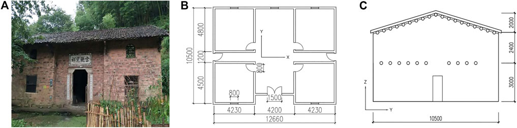
FIGURE 1. A brick-wood structure house with purlin roof in Jiangxi, China (Unit: mm) (A) Facade photo (B) Plan view (C) Side elevation.
Masonry structure research is based on experimental research and numerical simulation; the latter has the advantages of high efficiency, low cost, and is suitable for repeated tests and optimization analysis. Therefore, numerical simulation is used in many fields of earthquake engineering research (Masi et al., 2013; Wang et al., 2020; Chen et al., 2021). ADINA, a well-known finite element analysis software program, has powerful functions such as the stable solution of nonlinear analysis, and multi-physics simulation, so it can quickly solve complex nonlinear problems with almost absolute convergence. Accordingly, this paper adopted ADINA to carry out finite element numerical simulation on the purlin roof structure and established three types of working condition models: 1) the unreinforced original structure; 2) the traditional strengthening model reinforced with steel mesh cement mortar layer and reinforced mortar belt; and 3) the new strengthening model reinforced with the damping-limit device. Through modal analysis and seismic response analysis, the seismic performance, and damage characteristics of brick-wood structures were analyzed, the seismic responses of the structure before and after consolidation were compared, and the effects of traditional and new strengthening methods were discussed.
In general, there are two kinds of masonry wall simulation: integral modeling and separate modeling (Ma et al., 2001). Integral modeling simplifies the entire masonry wall, treats the masonry and mortar as the same material, ignores the interaction between them, and simulates it as a whole, which is suitable for the finite element analysis of large-scale structures. Separate modeling models the brick and mortar separately, considering the interaction between them. It is suitable for small-scale finite element analysis considering masonry failure mechanism, such as a single wall. Due to the complexity of the row-lock cavity wall and the large scale of the structure, this paper used integral modeling to establish the finite element model of the brick-wood structure. In addition, through the equivalent method, the wall thickness of the model was adjusted to 190 mm to improve the rationality of the row-lock cavity wall modeling and give the model the same dynamic characteristics as the actual structure.
The external walls of this kind of structure are composed of a mixture of brick masonry and adobe masonry. In this model, the brick masonry is reinforced with the outer steel mesh cement mortar surface layer. The vertical and horizontal steel wire diameter is 3 mm, and the spacing is 150 mm (Figure 2A). The hook screw is used for the steel mesh anchorage, and the spacing is not more than 300 mm. The adobe masonry part is enhanced by a double-sided steel mesh cement mortar surface. The vertical and horizontal steel wire diameter of the steel wire is also 3 mm, and the spacing is 120 mm. The mesh is anchored by steel wire with a diameter of 4 mm through the wall, and the spacing is not more than 500 mm. After the steel mesh is bound, cement mortar with a thickness of 20–30 mm and a strength grade of M10 is sprayed on or pressed into it.
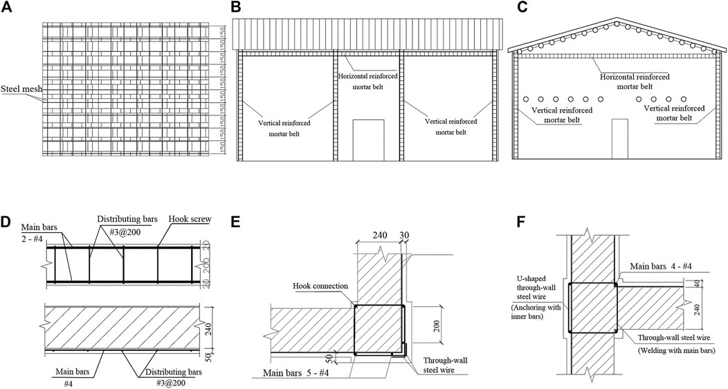
FIGURE 2. Traditional strengthening method (Unit: mm) (A) Steel wire mesh layout (B) Front elevation layout of mortar belt (C) Side elevation layout of mortar belt (D) Detail drawing of horizontal mortar belt (E) Detail drawing of L-shaped vertical mortar belt (F) Detail drawing of T-shaped vertical mortar belt.
Moreover, in the traditional strengthening method of this kind of structure, the horizontal reinforced mortar belts are arranged around the walls at the height of the cornice, and the vertical reinforced mortar belts are arranged at the corners of the walls and the junctions of the vertical and horizontal walls. This arrangement is similar to that of ring beams and structural columns, which can enhance the integrity and seismic performance of the house. Their layout positions are shown in Figures 2B,C. The height of the reinforced mortar belt is 240 mm and the thickness is 50 mm. Detailed drawings of two types of reinforced mortar belts are shown in Figures 2D–F, in which the vertical reinforced mortar belt is divided into “L” and “T” shapes.
In the previous surveys and earthquake damage analysis of rural residences, it was found that the triangular wall at the top of the brick-wood structure lacks a reliable tie, and the wooden purlins provide only limited longitudinal rigidity. In an earthquake, the wooden purlins are prone to slip or even fall off, and the walls collapse out of the plane. Finite element numerical simulation found a serious stress concentration between the wood purlin and the wall under the seismic load, leading to the partial or even complete failure of the gable peak. The seismic performance of the building is greatly reduced.
This study proposes a new type of damping-limit device for the seismic safety of the purlin roof structure. In the new strengthening model, 38 damping-limit devices were installed at the overlap joint of gables and wooden purlins on both sides of the original structure. The device is composed of a rubber partition layer and two identical steel gaskets with thicknesses of 20 and 10 mm, respectively. The rubber partition layer is square and steel gaskets with the same cross-section shape are connected on both sides of the rubber partition layer. The wooden purlin is passed through the rubber vibration isolation pad, and the purlin, rubber, and steel plate are bolted together, so that the purlin and the rubber vibration isolation pad are under the same force. When the seismic wave energy is transmitted to the wooden purlin, it will be dissipated through the rubber partition layer. The acceleration of the purlins and the structure on them is greatly reduced, so when the compression and impact on the wall are relieved, the stress concentration phenomenon at the contact part and the cracking of the wall are also significantly alleviated. Figure 3 shows the specific structure and installation diagram of the device.
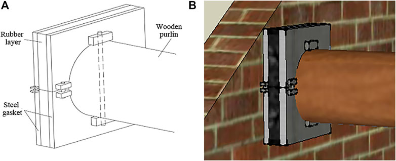
FIGURE 3. Novel damping-limit device (A) Structural figure (B) Installation diagram.
In this study, the masonry was regarded as homogeneous and isotropic material, and the influence of the mortar joint was considered only from the average, but the interface behavior between masonry and mortar was not considered. The stress-strain relationship of masonry under uniaxial compression proposed by Liu (2005) was adopted as the constitutive relationship of masonry:
Where σ and ε are the stress and strain of the masonry under compression, fm is the average value of the axial compressive strength of the masonry, and ε0 is the maximum strain corresponding to the maximum compressive stress, that is, the peak strain. Table 1 shows some main parameters of masonry materials.

TABLE 1. Masonry material parameters.
As a natural growth material, wood’s mechanical properties show obvious anisotropy. At the same time, it is affected by factors such as the growth environment, so the performance varies greatly. Therefore, this paper adopted the mechanical properties of the wood under the general ideal state, and referred to the literature (Ding, 2015) to obtain the parameters of the purlin (Table 2). In the table, EL, ER, and ET are the along-grain, transverse-grain tangential, and transverse-grain radial modulus of elasticity (MPa), respectively. μTL, μRT, and μLR are the along-grain radial, transverse-grain radial, and transverse-grain tangential Poisson ratio of the purlin, respectively. GLR, GRT, and GTL are the longitudinal and tangential, radial and longitudinal, tangential and radial shear modulus (MPa) of the purlin, respectively.

TABLE 2. Wooden purlin material parameters.
Rubber is a hyperelastic material that is, almost incompressible, with a Poisson ratio close to 0.5. The elastic modulus of this kind of material changes constantly in the process of loading, so the error of using elastic modulus and Poisson’s ratio to describe its mechanical properties is large, especially when it has obvious deformation. Accordingly, its mechanical properties need to be described by strain energy function, and the constitutive relation of each material is a special form of strain energy density function. To define this kind of material model, it is necessary to obtain the material stress-strain data or model material constants. The rubber material used in this study adopted the Ogden constitutive model (Başa and Itskov, 1998; Beda, 2005; Kim et al., 2012), which is a rubber material model whose strain energy density is represented by the principal elongation. Eq. 3 is the expression of its strain energy density.
where αn and μn are the material constants of the Ogden model, and λ1, λ2, and λ3 are the principal elongations in the three directions. Table 3 shows the stress-strain data fitted by the uniaxial tensile and plane shear test of rubber materials.
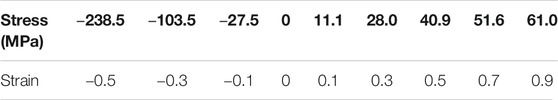
TABLE 3. Rubber material stress-strain data.
In this study, three seismic waves were selected for time history analysis of the model: EL-Centro, Taft, and Tianjin. The duration of EL-Centro wave and Taft wave is 40 s and that of Tianjin wave is 20 s. The acceleration time history curves of the three seismic waves in the east-west and north-south directions are shown in Figure 4. According to the Chinese code for seismic design of buildings (GB 50011-2010), the seismic fortification intensity of the main distribution areas of this structure is mostly 6 and 7 degrees, and the design basic seismic acceleration is not more than 0.1 g. Consequently, this research only modulated the peak amplitude of each seismic wave to 2.2 m/s2, which is the peak acceleration of a rare earthquake of 7 degrees.
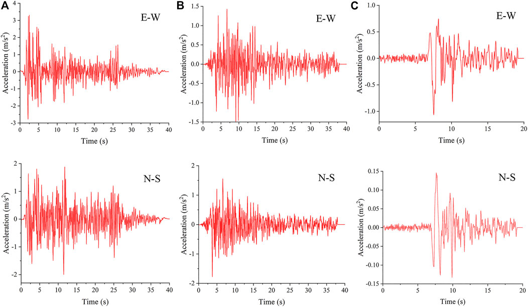
FIGURE 4. Time history curves of seismic wave acceleration (A) EL-Centro (B) Taft (C) Tianjin.
Modal is the inherent and integral characteristic of the elastic structure. Through the modal analysis method to analyze the features of the main modes of the structure in a certain susceptible frequency range, the actual vibration response generated by external or internal vibration sources in this frequency band can be inferred (Qu et al., 2017; Qu et al., 2018). In ADINA, by calculating the participating coefficients of each mode in the X, Y, and Z directions, the size relation of the influence coefficient of each mode in each direction is judged. Based on the modal frequency response theory, the dynamic stiffness of the response point is the superposition and coupling of the displacement of each mode to the point. The contribution of the modal to the displacement of the point is the modal participation factor. Through the frequency response analysis, we can find out the peak of some frequencies. Modal participation factor analysis can identify which main modal responses are superimposed at the peak frequency, and output several modes with large modal contribution according to the requirements, and optimize the design according to the modal shapes. Tables 4–6 respectively show the natural vibration period and modal participation coefficient of the first six modes of the three types of working condition models.
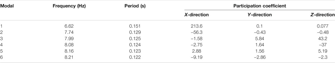
TABLE 4. Natural period and modal participation coefficient of the original model.

TABLE 5. Natural period and modal participation coefficient of the traditional strengthening model.
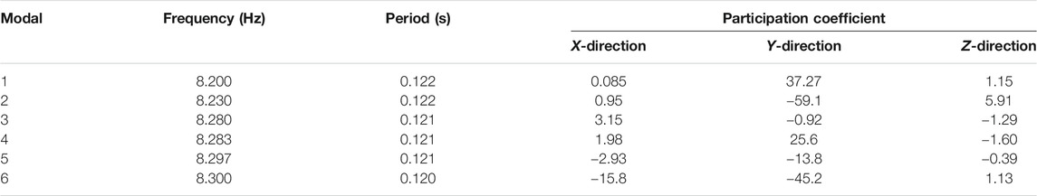
TABLE 6. Natural period and modal participation coefficient of the new strengthening model.
Yang et al. (1982) present the following empirical formula for the natural period of masonry structure:
Where T1 is the basic period and H0 is the height of the structure. According to the formula, T1 = 0.0168 × (7.4 + 1.2) = 0.144 s, which is close to the numerical simulation result of 0.151 s with an error of less than 5%, proving that the numerical simulation model is reasonable to a certain extent. Unlike other structures, the shaking table tests of the brick-wood structure are rare, and the numerical results in this study are only compared with the theoretical solution of the basic period of the masonry structure to verify the model.
The modal analysis result of the original structure model shows that it was more inclined to X-direction vibration. This may be because the structure has fewer longitudinal walls, and the top of the gable is constrained only by wooden purlins. Therefore, the X-direction vibration of the structure occurred before the Y-direction vibration, indicating that the X-direction stiffness of the structure is less than the Y-direction stiffness.
From the modal analysis of the traditional strengthening model, the vibration of the model was found to be more inclined to the Z-direction. This shows that the method has better X- and Y-direction constraints on the structure.
From the modal analysis of the new strengthening model, the Y-direction participation coefficient was shown to be greater than that of the X-direction, indicating that adding rubber vibration isolation pad constraints at the junction of the wooden purlin and gable can improve the X-direction’s stiffness. Although the new strengthening method is not as comprehensive as the traditional in terms of improving the seismic performance of the structure, the installation of the damping-limit device is simpler and the construction is more convenient.
Under the action of seismic waves, the displacement responses of the three structural models were analyzed separately, and the effect of reinforcement was analyzed by comparing the displacement changes with time and height. The model showed the same rule under the action of the three seismic waves. Due to space constraints, some of the diagrams take only the EL-Centro wave as an example to analyze the results.
Figure 5 shows the displacement cloud images of the three types of models extracted from ADINA when the maximum displacement occurred in two directions. The figure shows that the peak values of X-direction displacement of the three structures all appeared at the top of the gable, indicating that the out-of-plane stiffness of the top gable is smaller than that of the lower wall, which was most obvious in the original structure. The displacement image of the new strengthening model was similar to that of the original structure, but the value was much lower than that of the original one. In general, the effect of traditional reinforcement on displacement was the best.
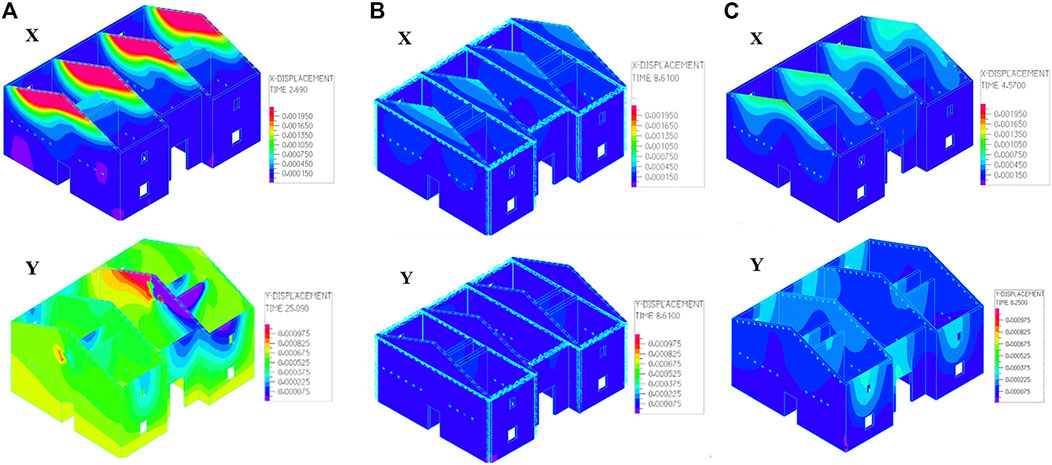
FIGURE 5. Displacement cloud images (EL-Centro) (A) Original model (B) Traditional strengthening model (C) New strengthening model.
Owing to the increase of the stiffness of the gable after the traditional reinforcement and the energy dissipation effect of the damping-limit device, the excessive displacement of the gable was significantly improved. At the moment of peak displacement, four nodes with larger displacements were selected: the highest node of the left and the middle gable, the cornice node of the front facade, and the highest node of the inner longitudinal wall. We then study the changes in their displacement time history under three conditions.
The displacement curves along the time of the four positions were studied sequentially, as shown in Figure 6. In a bi-directional earthquake, the peak of the gable of the original structure had a large deformation. The displacement time history image shows that the structural displacement tended to be stable after 30 s of ground motion. The lateral displacement of the structure tended to zero in the later stage of the time, and the cornice part remained elastic. Nevertheless, the longitudinal displacement was still vibrating at about 1 mm and did not tend to zero. Compared with the original structure, the longitudinal displacement of the traditional model was reduced about sixfold, and that of the new model was reduced fourfold.
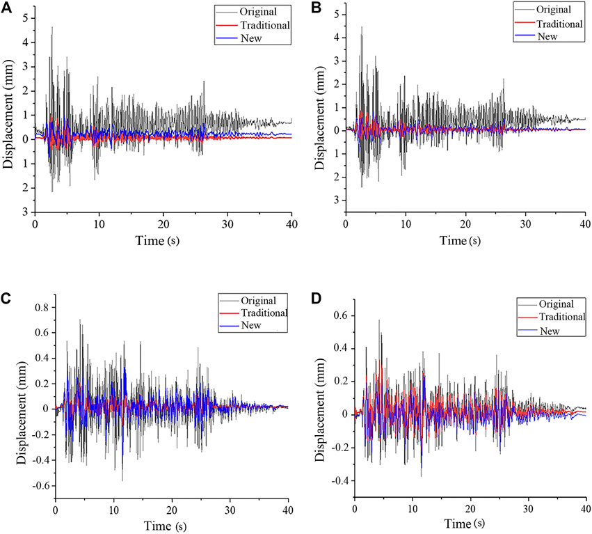
FIGURE 6. Displacement time history curves of four typical positions (EL-Centro) (A) X-displacement of the left gable peak (B) X-displacement of the middle gable peak (C) Y-displacement of the front facade cornice (D) Y-displacement of the inner longitudinal wall peak.
The reasons for this phenomenon are as follows: The gable wall is high, and the cross-sectional area of the wall is greatly reduced. However, the traditional residential structure does not provide consolidation measures at the gable, rigidity is considerably weakened. The longitudinal rigidity of the original structure is supported only by the wooden purlins, and the inertial force causes the gable to move too much out of the plane. As a result, some of the walls undergo plastic deformation at the later stage of the ground motion, and thus cannot be restored to their initial position. After traditional reinforcement, cement mortar surface layers are added on both sides of the top of the gable. The cement mortar is stronger than brick masonry, which can absorb seismic energy well and increase the out-of-plane stiffness of the gable. In the new strengthening model, the purlin passes through rubber and steel plates, which can increase its contact area with the wall. Moreover, rubber can dissipate the energy generated by seismic inertia force, improve the stress condition of components, and reduce the displacement of the peak of the gable.
Extract the corresponding data to draw the displacement envelope graph as shown in Figure 7 and the inter-story drift angle as shown in Table 7. It was found from the figure that the X-direction displacement of the wall below 5 m of the original structure did not change significantly along with the height, but that of the top of the gable increased suddenly. This is because of the substantial stiffness of the lower part of the cross wall, and the limited displacement under the support of the longitudinal wall, which is more resistant to seismic force. After retrofitting, the displacement of the wall at the whole height, especially at the top, was clearly reduced. In addition, judging by the inter-story drift angle (Jiang et al., 2018), the original structure is close to a moderately damaged state, and the two reinforced structures are in good condition.
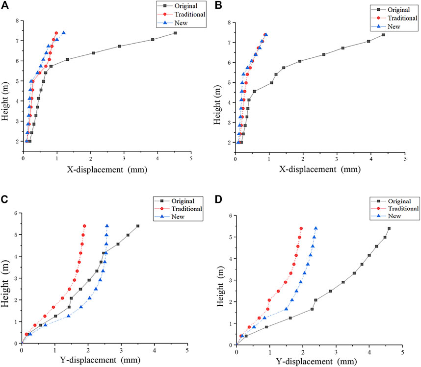
FIGURE 7. Envelope graphs of wall displacement (EL-Centro) (A) X-displacement of the left gable (B) X-displacement of the middle gable (C) Y-displacement of the front longitudinal wall (D) Y-displacement of the inner longitudinal wall.

TABLE 7. Maximum inter-story drift angle.
To explore the mechanical characteristics of the brick-wood structure under seismic action, the principal tensile stress cloud image was extracted from ADINA, and the mean principal tensile stress at the peak of the gable was calculated, as shown in Figure 8 and Table 8.
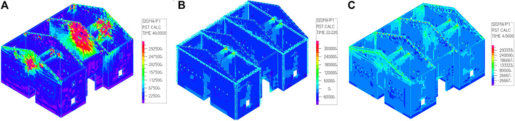
FIGURE 8. Principal tensile stress cloud images (EL-Centro) (A) Original model (B) Traditional strengthening model (C) New strengthening model.
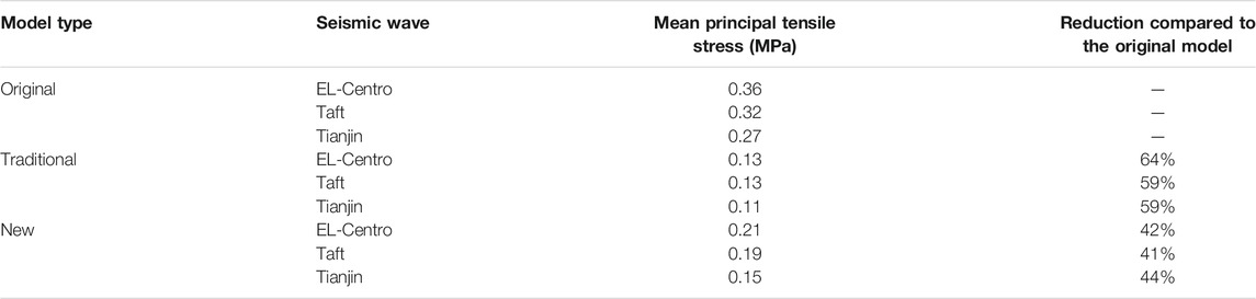
TABLE 8. Mean principal tensile stress of the gable peak.
The cloud images show that the stress concentration of the original structure was obvious at the junction of longitudinal and cross walls, the overlap between the purlins and the walls, and the peak of the gable. Some of the walls had exceeded the failure load of the material by 0.33 MPa and are in a state of failure. Among them, the top of the right cross wall in the middle was almost completely destroyed and there was a risk of collapse. The stress response of the lower part of the wall was good, and there was only slight damage at the corner of the window. After the traditional reinforcement, the stress concentration at the junction of the longitudinal and cross walls was significantly improved, and only slight wrecks occurred at the junction of the internal wall. After the strengthening of the damping-limit devices, the stress concentration at the top of the gable was also significantly improved, only minor damage occurred at the overlap of the purlins and the gable, the junction of the walls, and the surrounding of the opening. Table 8 shows that under the action of the three seismic waves, the mean value of the principal tensile stress at the gable peak of the traditional strengthening model is reduced by about 60% compared with the original structure, while that of the new strengthening model is reduced by about 40%. Both methods reduce the tensile stress at the peak of the gable. Of the two, the improvement effect of the traditional one is more significant, but considering factors such as cost and construction period, the damping-limit device is preferable.
Figure 9 and Table 9 show the shear stress cloud images extracted from ADINA, and the mean value of the shear stress at the bottom of the wall under the action of three seismic waves, respectively. The study found that in the original structure, the shear stress concentration at the bottom of the walls, the junction of the longitudinal and cross walls, and the peak of the gable was obvious, especially the peak and the bottom of the right cross wall in the middle had been damaged, and there was a risk of collapse. As the duration of the seismic wave increases, the plastic development became more obvious, and the damaged area at the junction of the walls showed an obvious downward trend. After the traditional reinforcement, only the junction of the internal walls and the openings were slightly damaged, which alleviated the excessive shear stress of the walls, and the mean value of the bottom shear stress was reduced by about 70%. After the new reinforcement, the top of the gable, the junction of the walls, and the openings were slightly damaged, and there was no plastic development phenomenon relative to the original structure. However, the reduction in the mean value of the bottom shear stress was very small, and the shear stress concentration had not been significantly improved compared to the original structure, indicating that the method has a limited effect on the lower part of the wall.
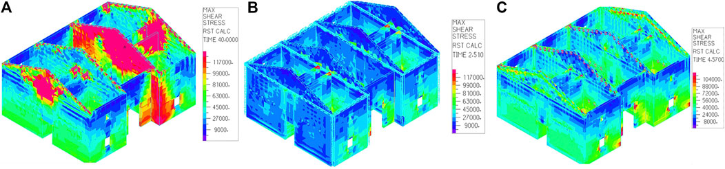
FIGURE 9. Shear stress cloud images (EL-Centro) (A) Original model (B) Traditional strengthening model (C) New strengthening model.
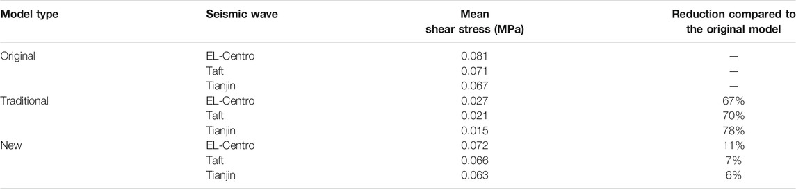
TABLE 9. Mean shear stress at the bottom of the wall.
The magnitude of the acceleration reflects the dynamic response of the house under the action of an earthquake. The greater the acceleration, the faster the speed change, and the more unfavorable the structural safety. Draw the acceleration time history curve of the three points A, B, and C, as shown in Figure 10.
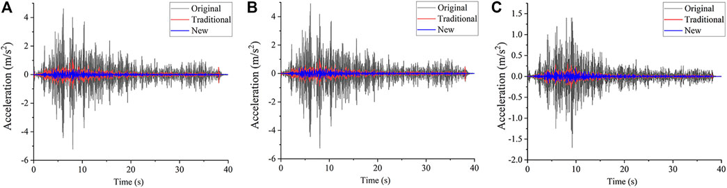
FIGURE 10. Acceleration response (EL-Centro) (A) X-acceleration at the peak of the left gable (B) X-acceleration at the peak of the middle gable (C) Y-acceleration at the cornice of the facade.
The X-direction acceleration of the original structure was increased by about 3.6 times compared with the amplitude-modulated seismic wave. The acceleration response was strong, and the range of change was large, which does serious damage to the structure. The traditional reinforcement failed to greatly reduce the acceleration response of the structure in the X-direction, indicating that although the displacement of the top gable was small, the swing speed changed rapidly. The new reinforcement significantly reduced the acceleration response of the wall. The maximum acceleration of the wall in the X-direction was only 1.1 m/s2, 50% lower than the acceleration of the seismic wave after amplitude modulation, which has a good shock absorption effect. This is because rubber can cushion the impact and the inertial force of the purlin on the wall. On the longitudinal wall, the acceleration response was far less intense than that of the horizontal wall. The Y-direction acceleration at the cornice was 1.6 m/s2, and the acceleration response was good.
Among the three seismic waves, the EL-Centro wave had the most violent response and the Tianjin wave had the least violent. The X-direction accelerations of the gable peak under the action of three seismic waves were 8, 4.3, and 3.1 m/s2, respectively. The magnifications were 3.64, 1.86, and 2.58, respectively.
In this study, numerical simulation was used to research the seismic performance and reinforcement effect of the brick-wood structure with purlin roof. Three types of models were established by finite element analysis software ADINA: the original structure, the strengthening model using the traditional method, and the strengthening model using the novel damping-limit device. The earthquake responses of the three models were compared, and the main conclusions are as follows:
1) The novel damping-limit device proposed in this paper can resolve the anti-seismic defects of the purlin roof structure. First, the device can limit the displacement of the purlins and prevent them from falling. In addition, the stress concentration phenomenon at the connection position of the wooden purlins and the walls was alleviated, and the average value of the main tensile stress at the peak of the gable was reduced by more than 40% compared with the original structure. The displacement and cracking of the gable peak had also been significantly improved, and the longitudinal displacement of this part had been reduced by four times compared with the original model.
2) The device has an obvious effect not only on the local but also on the seismic response of the structure. After the new method was used to strengthen the structure, the maximum inter-story drift angle of the structure under the action of the three seismic waves was only 23.8% of the original structure on average. The maximum acceleration of the wall in the X-direction was only 1.1 m/s2, about 50% lower than that of the seismic wave after amplitude modulation, indicating that the device also has a good control effect on the acceleration response of the walls. However, it has no obvious influence on the shear stress of the lower part of the walls.
3) The study found serious defects in the seismic performance of the unreinforced original structure. The walls, especially the peak of the gables, are prone to excessively large out-of-plane displacement in an earthquake. The maximum inter-story drift angle was 1/479, which has reached a moderately damaged state. Meanwhile, there was obvious stress concentration at the junction of longitudinal and cross walls, the bottom of the walls, and the peak of the gables, all of which are prone to local damage or even collapse.
4) The traditional strengthening method has a better effect on reducing the seismic response of structural walls such as displacement and acceleration. Nevertheless, this technique also has obvious disadvantages of being costly and time-consuming. Moreover, most of the work is done by small local engineering teams without construction qualifications, so the quality of reinforcement cannot be guaranteed.
5) Since the damping-limit device is developed to reduce the stress concentration at the gable peak and to prevent purlins from falling, it does not increase the stiffness and strength of the bearing walls. Therefore, the control of the stress at the foot of the house and the displacement of the walls is limited, and the reduction of the cracking of the cross walls is also lower than that of the traditional method. However, this method is convenient for construction and it is easy to ensure the quality of reinforcement, which is more suitable for seismic strengthening of rural houses. If this method is combined with local wall strengthening, the overall seismic performance of the structure can be greatly improved. Furthermore, with the development of new building materials, it is possible to consider using materials such as nylon plates instead of steel plates to further reduce the cost and facilitate application.
The raw data supporting the conclusion of this article will be made available by the authors, without undue reservation.
BC conceived the study and designed the research method. BJ wrote the paper and drew the charts. MW made constructive comments on the study. XL build the models and analyzed the data.
This work was financially supported by the National Natural Science Foundation of China (grant number 51868048); China Earthquake Administration Basic Research Project (grant number 2018D18).
The authors declare that the research was conducted in the absence of any commercial or financial relationships that could be construed as a potential conflict of interest.
All claims expressed in this article are solely those of the authors and do not necessarily represent those of their affiliated organizations, or those of the publisher, the editors and the reviewers. Any product that may be evaluated in this article, or claim that may be made by its manufacturer, is not guaranteed or endorsed by the publisher.
An, X., and Li, D. (2020). Typical Earthquake Damage Analysis of Ludian Earthquake with Ms 6. 5. Build Struct. 50 (7), 28–36. doi:10.19701/j.jzjg.2020.07.004
Başa, Y., and Itskov, M. (1998). Finite Element Formulation of the Ogden Material Model with Application to Rubber-like Shells. Int. J. Numer. Meth Engng 42 (7), 1279–1305. doi:10.1002/(sici)1097-0207(19980815)42:7<1279::aid-nme437>3.0.co;2-i
Basili, M., Vestroni, F., and Marcari, G. (2019). Brick Masonry Panels Strengthened with Textile Reinforced Mortar: Experimentation and Numerical Analysis. Constr Build Mater. 227, 117061. doi:10.1016/j.conbuildmat.2019.117061
Beda, T. (2005). Optimizing the Ogden Strain Energy Expression of Rubber Materials. J. Eng. Mater. Technol. 127 (3), 351–353. doi:10.1115/1.1925282
Borri, A., Castori, G., and Corradi, M. (2011). Shear Behavior of Masonry Panels Strengthened by High Strength Steel Cords. Constr Build Mater. 25 (2), 494–503. doi:10.1016/j.conbuildmat.2010.05.014
Chen, B., Wang, D., Chen, S., and Hu, S. (2021). Influence of Site Factors on Offshore Ground Motions: Observed Results and Numerical Simulation. Soil Dyn. Earthq Eng. 145, 106729. doi:10.1016/j.soildyn.2021.106729
Deng, M., Li, T., and Zhang, Y. (2020a). Compressive Performance of Masonry Columns Confined with Highly Ductile Fiber Reinforced Concrete (HDC). Constr Build Mater. 254, 119264. doi:10.1016/j.conbuildmat.2020.119264
Deng, M., Zhang, W., and Yang, S. (2020b). In-plane Seismic Behavior of Autoclaved Aerated Concrete Block Masonry Walls Retrofitted with High Ductile Fiber-Reinforced Concrete. Eng. Struct. 219, 110854. doi:10.1016/j.engstruct.2020.110854
Derakhshan, H., Walsh, K. Q., Ingham, J. M., Griffith, M. C., and Thambiratnam, D. P. (2020). Seismic Fragility Assessment of Nonstructural Components in Unreinforced Clay Brick Masonry Buildings. Earthquake Eng. Struct. Dyn. 49, 285–300. doi:10.1002/eqe.3238
Ding, Y. (2015). Study on Seismic Performance of Brick and Wood Structure Buildings in Western Villages (Xi’an (CHN): Xi’an University of Architecture and Technology). dissertation/master’s thesis.
ElGawady, M. A., Lestuzzi, P., and Badoux, M. (2006). Aseismic Retrofitting of Unreinforced Masonry Walls Using FRP. Compos. Part. B 37, 148–162. doi:10.1016/j.compositesb.2005.06.003
Jiang, L., Wang, Z., and Zhang, F. (2018). Damage Degree and Inter-Story Drift Angle Limit of Multi-Story Masonry Structures. J. Build Struc 39 (S2), 263–270. doi:10.14006/j.jzjgxb.2018.S2.036
Kim, B., Lee, S. B., Lee, J., Cho, S., Park, H., Yeom, S., et al. (2012). A Comparison Among Neo-Hookean Model, Mooney-Rivlin Model, and Ogden Model for Chloroprene Rubber. Int. J. Precis Eng. Man. 13 (5), 759–764. doi:10.1007/s12541-012-0099-y
Korkmaz, H. H., Korkmaz, S. Z., and Donduren, M. S. (2010). Earthquake Hazard and Damage on Traditional Rural Structures in Turkey. Nat. Hazards Earth Syst. Sci. 10 (3), 605–622. doi:10.5194/nhess-10-605-2010
Liu, G. (2005). “Study on Basic Mechanical Performance of Masonry Structure,” (Changsha (CHN): Hunan University). dissertation/master’s thesis.
Ma, G., Hao, H., and Lu, Y. (2001). Homogenization of Masonry Using Numerical Simulations. J. Eng. Mech. 127 (5), 421–431. doi:10.1061/(asce)0733-9399(2001)127:5(421)
Masi, A., Santarsiero, G., Lignola, G. P., and Verderame, G. M. (2013). Study of the Seismic Behavior of External RC Beam–Column Joints through Experimental Tests and Numerical Simulations. Eng. Struct. 52, 207–219. doi:10.1016/j.engstruct.2013.02.023
Mendes, N., Lourenço, P. B., and Campos-Costa, A. (2014). Shaking Table Testing of an Existing Masonry Building: Assessment and Improvement of the Seismic Performance. Earthq Engng Struct. Dyn. 43 (2), 247–266. doi:10.1002/eqe.2342
National Standards of the People’s Republic of China (2010). Code for Seismic Design of Buildings (GB 50011-2010). Beijing, China: China Architecture & Building Press.
Park, J., Towashiraporn, P., Craig, J. I., and Goodno, B. J. (2009). Seismic Fragility Analysis of Low-Rise Unreinforced Masonry Structures. Eng. Struct. 31 (1), 125–137. doi:10.1016/j.engstruct.2008.07.021
Qu, C., Yi, T., Li, H., and Chen, B. (2018). Closely Spaced Modes Identification through Modified Frequency Domain Decomposition. Measurement 128, 388–392. doi:10.1016/j.measurement.2018.07.006
Qu, C., Yi, T., Yang, X., and Li, H. (2017). Spurious Mode Distinguish by Eigensystem Realization Algorithm with Improved Stabilization Diagram. Struct. Eng. Mech. 63 (6), 743–750. doi:10.12989/sem.2017.63.6.743
Saleem, M. U., Numada, M., Amin, M. N., and Meguro, K. (2016). Shake Table Tests on FRP Retrofitted Masonry Building Models. J. Compos. Constr 20 (5), 04016031. doi:10.1061/(asce)cc.1943-5614.0000684
Shabdin, M., Zargaran, M., and Attari, N. K. A. (2018). Experimental Diagonal Tension (Shear) Test of Un-reinforced Masonry (URM) Walls Strengthened with Textile Reinforced Mortar (TRM). Constr Build Mater. 164, 704–715. doi:10.1016/j.conbuildmat.2017.12.234
Varum, H., Dumaru, R., Furtado, A., Barbosa, A. R., Gautam, D., and Rodrigues, H. (2018). “Seismic Performance of Buildings in Nepal after the Gorkha Earthquake,” in In Impacts and Insights of the Gorkha Earthquake. Editors D. Gautam, and H. Rodrigues (FL: Elsevier Inc Press), 47–63.
Wang, X., Zhao, W., and Kong, J. (2020). Numerical Investigation on the Influence of In-Plane Damage on the Out-Of-Plane Behavior of Masonry Infill Walls. Adv. Civ Eng. 2020, 1–16. doi:10.1155/2020/6276803
Xuan, W., Wu, G., Zuo, X., and Qian, X. (2016). Construction Technology and Engineering Application of Masonry Structure with Posted-Prefabricated Ring Beams and Constructional Columns. Constr Technol. 45 (16), 69–74. doi:10.7672/sgjs2016160069
Yang, Y., Yang, L., Gao, Y., Yang, Y., Lu, X., and Yang, G. (1982). Method of Damage Prediction for Existing Multi-Story Brick Buildings and its Reliability. Earthq Eng. Eng. Vib 2 (3), 75–86. doi:10.13197/j.eeev.1982.03.006
Keywords: purlin roof, brick-wood structure, seismic performance, seismic strengthening, damping-limit, numerical simulation
Citation: Chen B, Jia B, Wen M and Li X (2021) Seismic Performance and Strengthening of Purlin Roof Structures Using a Novel Damping-Limit Device. Front. Mater. 8:722018. doi: 10.3389/fmats.2021.722018
Received: 10 June 2021; Accepted: 05 August 2021;
Published: 13 August 2021.
Edited by:
Liang Ren, Dalian University of Technology, ChinaReviewed by:
Biao Hu, Shenzhen University, ChinaCopyright © 2021 Chen, Jia, Wen and Li. This is an open-access article distributed under the terms of the Creative Commons Attribution License (CC BY). The use, distribution or reproduction in other forums is permitted, provided the original author(s) and the copyright owner(s) are credited and that the original publication in this journal is cited, in accordance with accepted academic practice. No use, distribution or reproduction is permitted which does not comply with these terms.
*Correspondence: Ming Wen, d21ucHVAMTYzLmNvbQ==
Disclaimer: All claims expressed in this article are solely those of the authors and do not necessarily represent those of their affiliated organizations, or those of the publisher, the editors and the reviewers. Any product that may be evaluated in this article or claim that may be made by its manufacturer is not guaranteed or endorsed by the publisher.
Research integrity at Frontiers
Learn more about the work of our research integrity team to safeguard the quality of each article we publish.