 Jinhe Gao
 Jiahuan Xi2
 Baokui Chen
- 1Engineering Research Center of Nuclear Technology Application (East China Institute of Technology), Ministry of Education, Nanchang, China
- 2School of Civil and Architectural Engineering, East China University of Technology, Nanchang, China
- 3School of Civil Engineering and Architecture, Nanchang University, Nanchang, China
To clarify the mechanical properties of the U-shaped steel damper under tension and compression along the opening direction and the energy dissipation mechanism in the energy dissipation system, a mechanical model was established to describe the plastic failure response of the damper, and the formula for theoretical calculation of its mechanical properties was derived. Using the straight line segment length, radius of circular arc, and opening direction as parameters for testing four specimens, through the design of reasonable pulling and pressing fixture, four specimens were tested for tension and compression. The initial stiffness and yield load test results and theoretical analysis were good and verified that the opening direction of the U-shaped steel damper affected its mechanical performance. Further analysis of the U-shaped steel damper’s mechanical properties using numerical finite element analysis of the arc radius and the straight line segment length, width and thickness in relation to the initial stiffness shows that increasing the straight section length and end arc radius can reduce initial stiffness, and increase the thickness and width can increase initial stiffness.
Introduction
As one of the common types of dampers, steel damper was first proposed by Kelly et al. (1972) and Skinner et al. (1974), and then many scholars (Whittaker et al., 1991; Ricky Chan and Albermani, 2007; Lee et al., 2015; Xing and Guo, 2003; Wang, 2015; Yin et al., 2016; Huo et al., 2016; Qu et al., 2017) studied and improved various types of steel dampers. Among them, the U-shaped steel damper is a typical representative of the first generation of steel dampers. It is widely used in the vibration damping design of simple structures because of its simple structure, good energy dissipation performance, and low cost. The construction of the U-shaped steel damper and its possible deformation mode are shown in Figure 1.
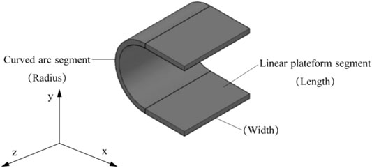
FIGURE 1. U-shaped steel damper.
Deformation mode A: the upper and lower linear platform sections are relatively moved in the x-direction. Li and Yao (1991), Yao (1997) studied the strength, stiffness, and dissipation performance of the U-shaped steel damper in the isolation device under low cyclic load. Zhao et al. (2017) proposed the expression of the mechanical properties of a U-shaped steel damper under a horizontal load. The mechanical model showed the mechanical properties of a U-shaped steel damper under a single load component. Based on the collected test data of 17 U-shaped steel dampers, Chong et al. (2015) summarized the design expressions of the initial stiffness and yield load of the damper and proposed a fine finite element analysis method.
Deformation mode B: the upper and lower linear platform sections have relative torsion in the z-direction. Deng et al. (2015) studied the mechanical properties of a U-shaped steel damper when it was subjected to torsional deformation under a lateral load outside the plane. Du et al. (2014), Du et al. (2016a), Du et al. (2016b), Han et al. (2016) conducted an experimental study on the influence of material hardness, constraint, and other factors on the mechanical properties and shock absorption and energy dissipation characteristics of the U-shaped steel damper and conducted theoretical and experimental research on the torsional deformation properties of the U-shaped steel damper of 65
A + B combined deformation mode: the upper and lower linear platform sections are relatively pulled and compressed in the y-direction. Jiao et al. (2015) and Enel et al. (2016) studied the mechanical properties of the U-shaped steel damper in isolation structures under bidirectional loads and confirmed that its energy dissipation properties were degraded under bidirectional loads. Through finite element analysis, Atasever et al. (2017) considered the mechanical response of the U-shaped steel damper under three working conditions of load input direction of 0°, 45°, and 90°.
A large number of studies show that the U-shaped metal damper has good energy dissipation performance, which can meet the requirements of structural response control parameters. However, due to the introduction of empirical coefficient based on the test results, the mechanical property expression lacks fine model and can not describe the plastic failure mechanism of the U-shaped steel dampers. At the same time, the mechanical properties of deformation mode C along the opening direction are seldom studied. In this paper, the U-type damper is taken as the research object, and two mechanical models of the U-shaped damper are established according to the different opening orientations of the damper. The mechanical properties of the U- shaped damper under the deformation mode C along the opening direction are studied, and the hysteretic properties and parameter sensitivity of the damper are analyzed.
Stiffness of a U-Damper
Two U-damper mechanical models are considered: Model I (Figure 2) and Model II (Figure 3). As depicted in Figure 2A, the U-damper includes straight-line (length: l0) parts and a semi-circle (radius, r) part. Photo 3 shows that the fixed condition of the top end of the U-damper can be realized using the stiffening plate at the high-strength bolted connection.
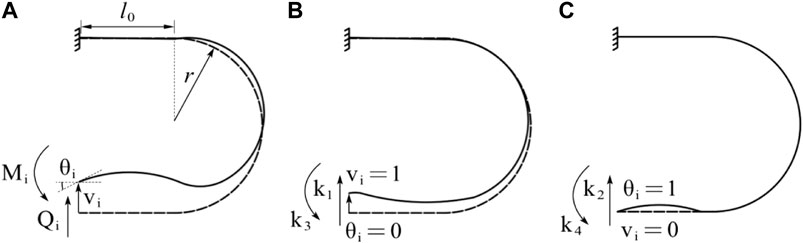
FIGURE 2. Force by unit displacement at the member end for Model I. (A) Mechanical model, (B) force by unit vertical displacement and (C) force by unit rotation angle.
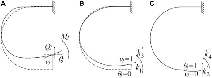
FIGURE 3. Force by unit displacement at the member end for Model II. (A) Load and boundary conditions. (B) Modification of the mechanical model.
Force and Displacement Relation for Model I
As depicted in Figure 2A, the shear force and bending moment at the node of the free end are denoted as Qi and Mi; the displacement and rotation angles are denoted as u and θ. The positive directions of forces and displacements are depicted in the figure. The horizontal node displacement is not considered.
k1, k3
In Figure 2B, load k1 and k3 moment k3 under the unit vertical displacement are calculable using the following equations obtained using the unit-load method.
From Eq. 1 and Eq. 2, k1 and k3 can be derived respectively as:
k2,k4
In Figure 2C, in which the U-damper is subjected to unit rotation angle at the free end, k2 and k4 can be derived using the method explained above:
Stiffness Matrix
Form Eqs 1–6, the force and displacement relation of the member end can be expressed as:
Force and Displacement Relation for Model II
Using the same method used for Model I, the member free end force and displacement relation for Model II, as portrayed in Figure 3, are obtainable as:
Unidirectional Tension-Compression Test of the Damper
Test Specimens
According to the different opening directions, the specimens of the U-shaped steel damper tension-compression test are divided into two groups: A and B. The two groups of specimens are made of SNB400. The specimens are composed of a connecting plate clamp, a U-shaped damper, a movable hinge device, and a filling plate, and a U-type damping and connecting plate are connected by high-strength bolts. The specific structure of the specimens and the U-type damping is shown in Figures 4, 5. The thickness of the connecting plate
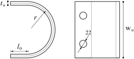
FIGURE 4. U-shaped damper.
FIGURE 5. Specimen structure.
Mechanical Properties of Specimens
This section combines the U-shaped steel damper and the test fixture as the research object to analyze the mechanical properties of the U-shaped steel damper during tension and compression. It analyzes the mechanical properties of the U-shaped steel damper according to the mechanical properties expression of the U-shaped steel damper derived in Force and displacement relation for Model I.
With a monomer U-shaped steel damper as the research object, a U-shaped steel damper with a hinged connection of two steel plates together and a connection plate assumption for the rigid plate only consider the U-shaped steel damper end vertical deformation influence on stiffness, without considering the horizontal deformation according to the mechanical model is deduced. Mechanical Model I and Mechanical Model II were established for the U-shaped steel damper specimens with different opening directions, as shown in Figure 6. To distinguish the difference when the bending deformation of the connecting plate is considered, the mechanical models of the U-shaped steel damper device with the connecting plate as a rigid plate are collectively referred to as the R model.
FIGURE 6. The mechanical model of the specimen with the connecting plate as the rigid plate (R model). (A) R–I, (B) R–II.
Mechanical Model of R-I
As shown in Figure 6A , one end of the U-shaped steel damper is engaged with the rigid plate at node 2, and the in-plane hinge constraint is carried out at node 4. At the same time, there is vertical load P and vertical displacement at rigid plate joint 1. The corresponding U-shaped steel damper has vertical load-displacement V, bending moment M, and rotation angle at node 2. Table 1 shows the free end load value of the U-shaped steel damper specimen.
TABLE 1. Test specimens.
The stiffness matrix of R-I:
Where Pu is a horizontal load and u is a horizontal displacement:
Since the clamp is regarded as a rigid plate, then:
The bending moment
Mechanical Model of R-II
Compared with the R-I mechanical model, its opening direction is opposite:
Intensity Assessment
For the U-shaped metal damping deformation mode studied in this paper, based on the distribution law of internal forces of bending moment, the U-shaped metal damping yield is defined when the bending moment at the third central node of the arc reaches the full interface plastic bending moment Mp. The plastic bending moment of full section Mp is:
The yield strength measured by the material property test is

TABLE 2. Load value of free end of U type steel damper.
As shown in Figure 6, the vertical displacement at the loading node 1 of the specimen is
For Figure 6A, according to Eq. 7, Eq. 12, Eq. 13, the internal force bending moment at the central node 3 of the U-shaped metal damping circular arc is:
When M = Mp, the U-shaped metal damping yields, and the vertical yield displacement at node 2 is denoted as
For Figure 6B in the model shown in , the bending moment of internal force at the central node 4 of the U-shaped metal damping arc is:
When M reaches MP, the U-shaped steel damper yields, similarly, the vertical yield displacement at the loading end of the specimen can be obtained.
Loading Program
The test device of the U-shaped steel damper is shown in Figure 7. Vertical load is applied by a microcomputer-controlled electro-hydraulic servo universal testing machine (model SHT4605). The loading speed is controlled at 0.1 mm/s, and a cable displacement meter is installed on both sides of the U-shaped steel damper to measure the vertical displacement at the damper opening.
FIGURE 7. Test device. (A) Tension test (B) Compression test.
Test Results
The load-displacement curve of the specimen is shown in Figure 8. The tangent stiffness is 1/3 of the initial stiffness, which is defined as the yield point. Table 3 shows the comparative analysis of theoretical and experimental results. The test error of yield load and yield displacement is kept within 20%.
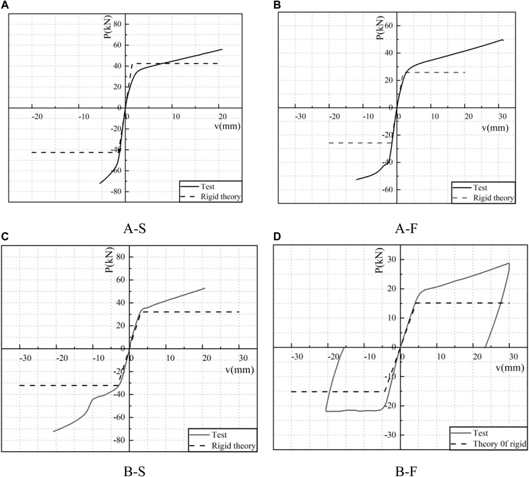
FIGURE 8. Experimental and theoretical load-displacement curves. (A) A–S, (B) A–F, (C) B–S, (D) B–F.
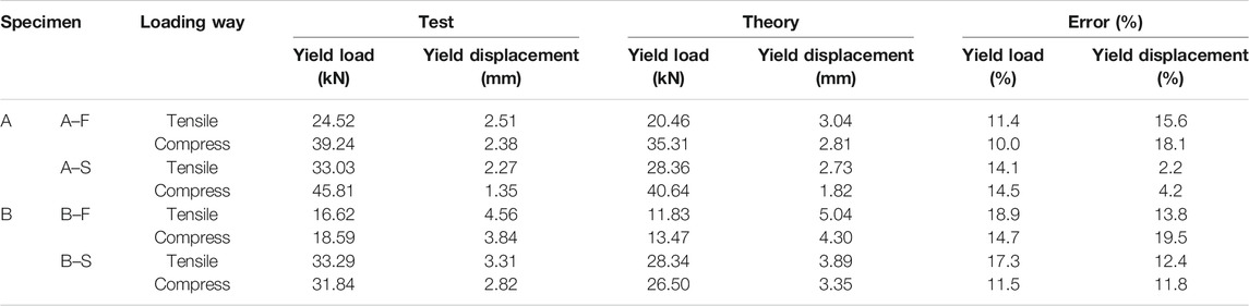
TABLE 3. Comparison between experiment and theory.
The influence of the U-shaped steel damper opening orientations: different U-shaped steel damper opening orientations have different initial stiffness. The initial stiffness and yield load of the damper whose opening is towards the articulated constraint point are both higher under tension and compression. It can be seen that the opening orientation of the U-shaped steel damper affects its mechanical properties.
The influence of radius size of an arc segment of a U-shaped steel damper: the initial stiffness of a U-shaped steel damper varies with the radius of the arc segment. Compared with the specimens in Group A, the specimen in Group B with the larger radius of the U-shaped steel damper arc segment has a larger yield displacement and a smaller yield load; that is, its initial stiffness is smaller. The above results show that the initial stiffness of the U-shaped steel damper is inversely proportional to the radius.
According to the comparison between the theoretical and experimental results, it can be seen that the opening orientation of the U-shaped steel damper during installation influences the response of the component. The mechanical property design expression should be combined with the mechanical property expression of the single U-shaped steel damper, and the load combination caused by the actual installation should be considered.
Finite Element Analysis
Introduction of Model
ANSYS software was used to establish an accurate finite element model to verify the test results and stress response analysis. The clamping plate and U-shaped steel damper are simulated with 4-node SHELL181. According to the test, the elastic modulus of the material obtained is 205,369 MPa, the Poisson’s ratio is 0.3, the yield strength is 306 MPa, and the ultimate strength is 450 MPa Link180 rod element was used to simulate the hinged restraint device. Multi-linear material model was employed for the U-shaped steel damper. Figure 9 is the finite element model of the specimen. The astatic cyclic loading process is adopted, controlled by displacement, to study the energy dissipation capacity of the damper. Figure 10 shows the cyclic loading displacement and the number of cycles.
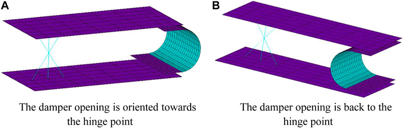
FIGURE 9. Finite element model. (A) The damper opening is oriented towards the hinge point. (B) The damper opening is back to the hinge point.
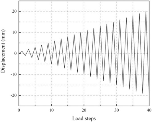
FIGURE 10. Loading system.
Finite Element Analysis of Unidirectional Tension and Compression
Through unidirectional tension and compression simulation of the finite element model, its stress nephogram Figure 11 was obtained. The deviation between the model data and the theory is small, and the degree of coincidence is high. It is shown that the numerical model has good accuracy.
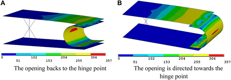
FIGURE 11. Stress nephogram. (A) The opening backs to the hinge point. (B) The opening is directed towards the hinge point.
Analysis of Hysteretic Property
Figure 12 depicts the load and displacement relations obtained in the finite element analysis. The hysteresis curve obtained from the finite element analysis is full and shuttle-shaped, which indicates that the U-shaped steel damper has good energy dissipation performance. The skeleton curve is shown in Figure 13 from the hysteretic loop curve. The mechanical properties of the steel damper calculated by the finite element method are shown in Table 4. As can be seen from the table, the initial stiffness of specimen A–S is 1.41 times that of specimen A–F, and the yield load is 1.29 times that of specimen A–F. The initial stiffness of specimen B–S is 1.91 times that of specimen B–S, and the yield load is 1.54 times that of specimen B–S. These results show that the initial stiffness and yield displacement of the steel damper with the opening towards the hinge point are larger than those with the opening back towards the hinge point.
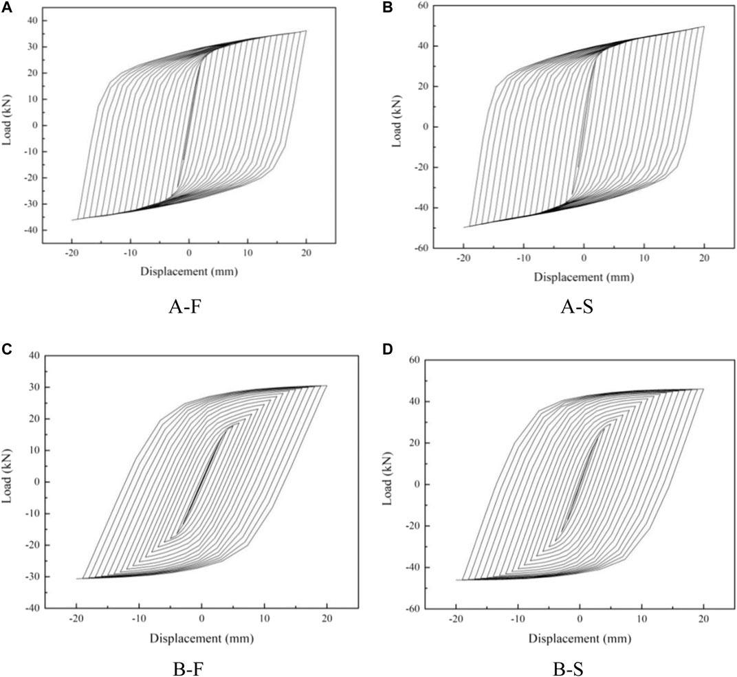
FIGURE 12. Force-displacement hysteretic curve of the damper. (A) A–F, (B) A–S, (C) B–F, (D) B–S.

FIGURE 13. The skeleton curve of the damper.
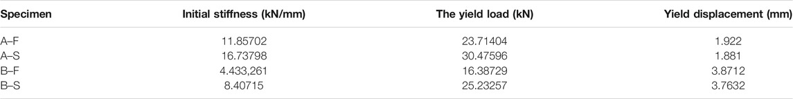
TABLE 4. Mechanical behavior of a finite element.
Equivalent lateral stiffness:
Where
According to the formula, the equivalent lateral stiffness of each cycle loading can be obtained, and the stiffness degradation curve is shown in Figure 14. As can be seen from the figure, the stiffness of the secant isoline of each group of specimens showed obvious stiffness degradation at the first loading stage. The stiffness of specimens A–S was always greater than that of specimens A–F, and the stiffness of specimens B–S was always greater than that of specimens B–F.
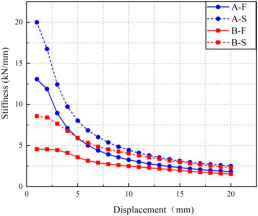
FIGURE 14. Stiffness degradation curve.
The equivalent lateral stiffness of the last cycle of cyclic loading calculated according to the formula is shown in Table 5. The equivalent lateral stiffness of A–S is 1.32 times that of A–F, and the equivalent lateral stiffness of B–S is 1.51 times that of B–F. The results show that the U-shaped damper whose opening is toward the hinge point has higher equivalent lateral stiffness. The maximum hysteretic loop area in Table 5 is the hysteretic loop area corresponding to the maximum displacement loading. The hysteretic loop area represents the amount of energy consumed by the U-shaped steel damper.
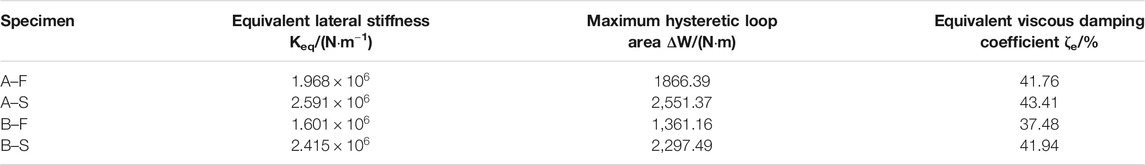
TABLE 5. Damping performance comparison.
The equivalent viscous damping coefficient is an important index to judge the energy dissipation capacity of a structure or member in earthquake resistance.
Where EDS is hysteretic damping energy dissipation, and is equal to the area surrounded by the curve at the maximum displacement; ES is the maximum strain energy (Zhou, 2013).
The equivalent viscous damping coefficient is related to the displacement of cyclic loading. The larger the energy dissipation effect is, the more obvious it is. The equivalent viscous damping coefficients listed in Table 5 all correspond to the values at the maximum cyclic loading displacement, so the damping coefficients are significant. It can be seen from the table that the equivalent viscous damping coefficient is A–S > A–F and B–S > B–F, indicating that the U-shaped damper whose opening is toward the hinge point has a more obvious energy dissipation effect.
Parameter Sensitivity Analysis
Geometric parameters have an important effect on the mechanical properties of U-shaped steel dampers. The parameter sensitivity of the component was analyzed by ANSYS finite element software. A model with a length of 40 mm, a width of 100 mm, a thickness of 9 mm, and a radius of 40 mm was taken as the initial model, and the initial stiffness of components under different parameters was compared and analyzed.
Figure 15A shows the curve of length and initial stiffness. The length parameter range is 15–200 mm, and the group distance is 5 mm. Other parameters are consistent with the original model. As the length of the U-shaped damper increases, its initial stiffness decreases and approaches zero. The length is inversely proportional to the initial stiffness and is more sensitive in the 15–55 mm range.
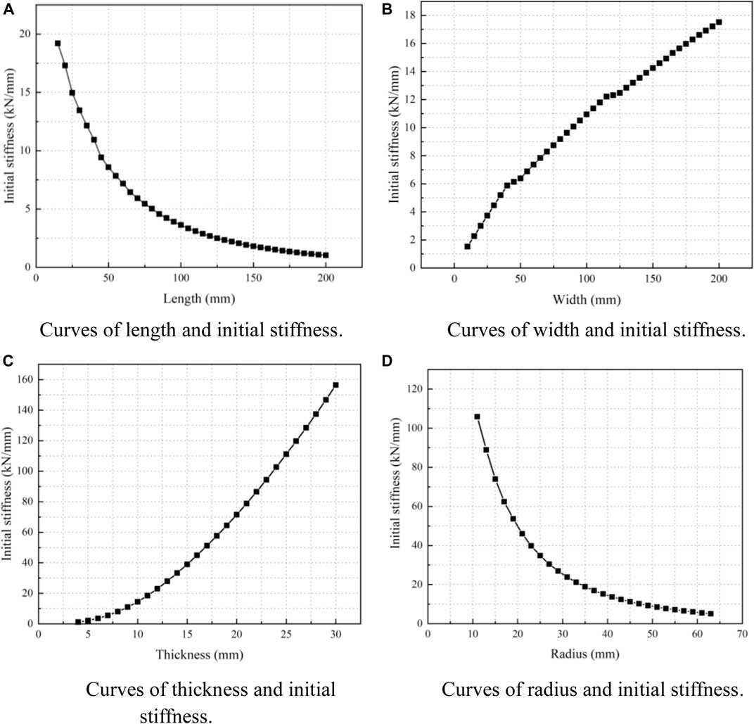
FIGURE 15. Curves of parametric analysis. (A) Curves of length and initial stiffness. (B) Curves of width and initial stiffness. (C) Curves of thickness and initial stiffness. (D) Curves of radius and initial stiffness.
Figure 15B shows the curve of width and initial stiffness. Except for width, other parameters are consistent with the original model. The width parameter range is 10–200 mm, group distance is 5 mm. As the width of the U-shaped damper increases, its initial stiffness increases, and its sensitivity is larger in the range of 10–40 mm.
Figure 15C shows the curve of thickness and initial stiffness. Except thickness, other parameters are consistent with the original model. Thickness range is 4–30 mm, group distance is 1 mm.As the thickness increases, its initial stiffness increases, and the greater the thickness, the more sensitive it is.
Figure 15D shows the curve of radius and initial stiffness. Except radius, other parameters are consistent with the original model, the radius range is 11–63 mm, group distance is 2 mm. The initial stiffness decreases with the increase of radius, and it is more sensitive in the range of 11–23 mm. It can be seen from the figure that the parameters of U-shaped metal damper have a great influence on its initial stiffness, which should be considered reasonably in the design and application.
Conclusion
In this paper, a theoretical formula for the mechanical properties of the U-shaped steel damper is presented. In addition, the experimental verification and finite element analysis of the U-shaped steel damper are also carried out. The main research results are summarized as follows.
When a single U-shaped steel damper has tension and compression, the end-load of the damper is the coupling of vertical force and bending moment. When the opening direction is different, the performance expression form is the same, but the vector positive and negative regulations are different, which should be differentiated in practical application.
According to the load-displacement relationship curve, the mechanical properties of U-shaped steel dampers vary with the opening directions in the tension-compression experiment. Through the comparative analysis of theoretical and experimental results, it is shown that the mechanical property expression of the U-shaped steel damper proposed in this paper is reasonable and feasible and can describe the plastic failure mechanism of a U-shaped steel damper, which provides a theoretical basis for the design and manufacture of the U-shaped steel damper.
In the study of finite element analysis, the results of finite element analysis obtained through monotonic loading are in good agreement with the test results. The hysteretic curves of all specimens obtained through repeated static loading simulation of a U-shaped steel damper by finite element software are full and in the shape of a shuttle. Compared with the damper whose opening is back to the hinged point, the damper whose opening is towards the hinged point has higher initial stiffness and equivalent viscous damping coefficient, and the energy dissipation effect is more obvious.
Parameters of U-shaped steel dampers greatly influence their initial stiffness, which should be taken into account in the design and application of U-shaped steel dampers.
Parameters of U-shaped steel dampers greatly influence their initial stiffness. The result shows that increasing the straight section length and end arc radius can reduce initial stiffness, and increase the thickness and width can increase initial stiffness.
Data Availability Statement
The original contributions presented in the study are included in the article/supplementary material, further inquiries can be directed to the corresponding author.
Author Contributions
JG:Formal analysis, funding, writing review and editing JX:Survey method, project management, data management YX:First draft writing, data management JD:Project management, supervision JZ:Software, data management YC:Supervision, fund acquisition, verification BC:Supervision, fund acquisition, verification.
Conflict of Interest
The authors declare that the research was conducted in the absence of any commercial or financial relationships that could be construed as a potential conflict of interest.
Publisher’s Note
All claims expressed in this article are solely those of the authors and do not necessarily represent those of their affiliated organizations, or those of the publisher, the editors and the reviewers. Any product that may be evaluated in this article, or claim that may be made by its manufacturer, is not guaranteed or endorsed by the publisher.
Acknowledgments
The authors gratefully acknowledge the financial supports from Engineering Research Center of Nuclear Technology Application foundation (East China University of Technology), Ministry of Education (HJSJYB 2016-8, HJSJYB 2015-10), Education Department of Jiangxi Province (GJJ180373) and National Natural Science Foundation of China, 51868048.
References
Atasever, K., Celik, O. C., and Yuksel, E. (2017). Modelling Hysteretic Behaviour of U-Shaped Steel Dampers. Lullanagar, Pune: EUROSTEEL, 3239–3248.
Chong, X., Hou, L. B., Chen, X., Xie, L. L., Jiang, Q., and Miao, Q. S. (2015). Research on Mechanical Performance and Numerical Simulation Analysis Method of U-Shaped Steel Damper [J]. Building Structures 1 (01), 114–120.
Deng, K. L., Pan, P., Su, Y. K., Sun, J. B., and Qian, J. R. (2015). Experimental Study on Transverse Performance of Slotted U-Shaped Metal Yield Damper [J]. J. Vibration Shock 34 (12), 157–163.
Du, H. K., Han, M., Yan, W. M., et al. (2016a). Influence of Hardness and Number of Layers on Mechanical Properties of U-Shaped Steel Plates [J]. Eng. Mech. 33 (2), 101–106.
Du, H. K., Han, M., Yan, W. M., et al. (2016b). Test of Bearing Capacity and Elastoplastic Regression Analysis of Manganese Steel U-Shaped Limiter [J]. J. Building Structures 37 (8), 108–114.
Du, H. K., Han, M., and Yan, W. M. (2014). Study on Calculation Method of Mechanical Properties of Constrained U-Shaped Steel Plate [J]. Chin. J. Civil Eng. 47 (2), 158–162.
Enel, D., Kishiki, S., Yamada, S., Jiao, Y., Konishi, Y., Terashima, M., et al. (2016). Experimental Study on the Bidirectional Inelastic Deformation Capacity of U-Shaped Steel Dampers for Seismic Isolated Buildings [J]. Earthquake Eng. Struct. Dyn. 45, 173–192. doi:10.1002/eqe.2621
Han, M., Feng, H. D., and Du, H. K. (2016). Research on Torsional Performance of U-Shaped 65mn Steel Plate Limiter [J]. J. Beijing Univ. Civil Eng. Architecture 32 (04), 1–5+22.
Huo, L., Qu *, C., and Li, H. (2016). Robust Control of Civil Structures with Parametric Uncertainties through D-K Iteration. Struct. Des. Tall Spec. Build. 25 (3), 158–176. doi:10.1002/tal.1233
Jiao, Y., Kishiki, S., Yamada, S., Ene, D., Konishi, Y., Hoashi, Y., et al. (2015). Low Cyclic Fatigue and Hysteretic Behavior of U-Shaped Steel Dampers for Seismically Isolated Buildings under Dynamic Cyclic Loadings [J]. Earthquake Eng. Struct. Dyn. 44, 1523–1538. doi:10.1002/eqe.2533
Kelly, J. M., Skinner, R. I., and Heine, A. J. (1972). Mechanisms of Energy Absorption in Special Devices for Use in Earthquake Resistant Structures. Bnzsee 5 (3), 63–88. doi:10.5459/bnzsee.5.3.63-88
Lee, C.-H., Ju, Y. K., Min, J.-K., Lho, S.-H., and Kim, S.-D. (2015). Non-uniform Steel Strip Dampers Subjected to Cyclic Loadings. Eng. Structures 99 (Sep. 15), 192–204. doi:10.1016/j.engstruct.2015.04.052
Li, S. X., and Yao, Q. F. (1991). Application Research of Basement Isolation of Multi-Layer brick concrete Structure [J]. J. Xi ’a Univ. Architecture Technol. (Natural Sci. Edition) (04), 411–418.
Qu, C. X., Li*, H. N., Huo, L. S., and Yi, T. H. (2017). Optimum Value of Negative Stiffness and Additional Damping in the Civil Structures [J]. ASCE J. Struct. Eng. 143 (8), 04017068. doi:10.1061/(asce)st.1943-541x.0001805
Ricky Chan, W. K., and Albermani, F. (2007). Experimental Study of Steel Slit Damper for Passive Energy Dissipation [J]. Eng. Structures 30 (4), 1058. doi:10.1016/j.engstruct.2007.07.005
Skinner, R. I., Kelly, J. M., and Heine, A. J. (1974). Hysteretic Dampers for Earthquake-Resistant Structures. Earthquake Engng. Struct. Dyn. 3 (3), 287–296. doi:10.1002/eqe.4290030307
Wang, Q. L. (2015). Experimental Study on the Damper Performance of SMA Metal Rubber Damper [J]. J. Xi’, a Univ. Architecture Technol. (Natural Sci. Edition) 47 (006), 804–807.
Whittaker, A. S., Bertero, V. V., Thompson, C. L., and Alonso, L. J. (1991). Seismic Testing of Steel Plate Energy Dissipation Devices. Earthquake Spectra 7 (4), 563–604. doi:10.1193/1.1585644
Xing, S. T., and Guo, X. (2003). Study on Mechanical Properties and Shock Absorbing Effect of a New Kind of Soft Steel Damper [J]. Earthquake Eng. Eng. Vibration 23 (6), 179–186.
Xu, B. Y., and Liu, X. S. (1995). Application of Elastic-Plastic Mechanics [M]. Beijing: Tsinghua University Press, 409–411.
Yao, Q. F. (1997). Analysis of Limitation and Energy Dissipation Performance of U-Shaped Steel Strip [J]. J. Xi ’a Univ. Architecture Technol. (Natural Sci. Edition) (01), 24–28.
Yin, W. H., Chen, L., and Wang, J. F. (2016). Study on the Performance of a New Type of Shearing Metal Energy Dissuaders with Buckling Constraints [C]. The Ninth National Symposium on Earthquake Prevention and Mitigation Engineering, 907–914.
Keywords: mechanical properties, initial stiffness, yield load, parameter analysis, U-shaped steel damper
Citation: Gao J, Xi J, Xu Y, Ding J, Zhu J, Chang Y and Chen B (2021) Analysis of the Mechanical Properties and Parameter Sensitivity of a U-Shaped Steel Damper. Front. Mater. 8:713221. doi: 10.3389/fmats.2021.713221
Received: 22 May 2021; Accepted: 31 May 2021;
Published: 27 July 2021.
Edited by:
Yang Zhang, Dalian University of Technology, ChinaCopyright © 2021 Gao, Xi, Xu, Ding, Zhu, Chang and Chen. This is an open-access article distributed under the terms of the Creative Commons Attribution License (CC BY). The use, distribution or reproduction in other forums is permitted, provided the original author(s) and the copyright owner(s) are credited and that the original publication in this journal is cited, in accordance with accepted academic practice. No use, distribution or reproduction is permitted which does not comply with these terms.
*Correspondence: Jinhe Gao, amhnYW9AZWN1dC5lZHUuY24=