 Jing Ji
 Runbao Zhang1
94% of researchers rate our articles as excellent or good
Learn more about the work of our research integrity team to safeguard the quality of each article we publish.
Find out more
ORIGINAL RESEARCH article
Front. Mater., 25 May 2021
Sec. Structural Materials
Volume 8 - 2021 | https://doi.org/10.3389/fmats.2021.693905
This article is part of the Research TopicInnovative Use of FRP and Nanofiber-based Materials in EngineeringView all 8 articles
In order to study the flexural behavior of simply supported beams consisting of gradient concrete and GFRP bars, 28 simply supported beams were designed. The main parameters included the strength grades of high-strength concrete (HSC), GFRP reinforcement ratio, and sectional height of HSC. Based on nonlinear constitutive models of materials, meanwhile, considering the bond slip between concrete and GFRP bars, five simply supported beams with gradient concrete and five simply supported beams with GFRP bars were simulated, respectively. Then the mid-span load–displacement curves of beams were obtained. By comparing with the experimental data, the rationality of material constitutive models and finite element modeling was verified. Based on this, the parameter analysis of the beams with GFRP bars and gradient concrete was carried out, and the failure modes of the beams were obtained through investigation. The results show that the failure process of the beams can be divided into two stages: elastic stage and working stage with cracks. With the increase of GFRP reinforcement ratio, the flexural bearing capacity of the beams does not change significantly, while their stiffness increases gradually. The flexural bearing capacity of the beams can be significantly improved by appropriately increasing the strength and sectional height of HSC. The ultimate bearing capacity of the beams is 40% higher than that of the GFRP concrete beams. Finally, based on the plane-section assumption, the calculation formula of normal-section flexural bearing capacity of this kind of beams is proposed through statistical regression method.
High-strength concrete (HSC) has been used in high-rise buildings, long-span bridges, and some special structures for its high compressive strength, high density, and low porosity (Idris and Ozbakkaloglu, 2014; Erfan et al., 2020). However, the application of HSC in practical engineering is limited because of its poor deformation ability, easy cracking, and complicated material ratio requirements. Provided HSC is used only in the key parts of the engineering structural members and normal-strength concrete (NSC) is used in other parts, the advantages of high compressive strength of HSC and the economics of NSC can be fully utilized to realize the organic combination of them. Based on this, a kind of flexural member consisting of gradient concrete is proposed, in which the compression zone is made of HSC, the tension zone is made of NSC, and GFRP bars are adopted as the tension bars. During the pouring period, the upper surface of NSC should keep rough to ensure the effective bonding between the NSC and the later-period poured HSC.
Iskhakov et al. first proposed double-layer beams consisting of gradient concrete, in which HSC could be used in compression zone and NSC could be used in tension zone (Iskhakov and Ribakov, 2007). The calculation method of volume ratio of prestressed double-layer concrete beams mixed with steel fiber was proposed (Iskhakov and Ribakov, 2008). It was also found that fiber weight could substitute for fiber volume ratio, and the fiber content in concrete could be more accurately defined by fiber weight (Holschemacher et al., 2012). Brian et al. established a nonlinear finite element model which could effectively predict the shear behavior of double-layer composite beams based on the theory of higher-order beams (Brian et al., 2017). Monetto et al. simulated the interface failure of partial shear-connected double-layer beams and determined the mathematical model of this type of composite beams (Monetto and Campi, 2017). Magnucki et al. studied double-layer beams with different mechanical properties, thicknesses, and widths. According to the principle of potential energy balance, the calculation methods of beam deflection, normal stress, and shear stress were obtained (Magnucki et al., 2020). Zhou et al. carried out the flexural test of reinforced gradient concrete beams, and obtained the calculation method of the cracking moment and maximum crack width of this type of beams (Zhou and Zheng, 2011a; Zhou and Zheng, 2011b; Zhou and Zheng, 2012). Tests on flexural behavior of seven simply supported beams consisting of gradient concrete were conducted by Yang (Yang, 2014), and the results showed the cross-sectional flexural bearing capacity of beams consisting of gradient concrete increased gradually with the increase of the reinforcement ratio within the range of test parameters. Dong et al. revised the formula for the maximum crack width of flexural members consisting of FRP bars and concrete, and the calculated value of the revised formula agrees well with the experimental data (Dong and Wu, 2017). Wang conducted static tests on flexural behavior of FRP concrete beams, obtained the failure modes and flexural bearing capacity of the beams, and finally established the calculation formula for the flexural bearing capacity of this type of beams (Wang, 2018). Zhao et al. carried out the tests on flexural behavior of FRP rubber aggregate concrete beams, and got the influence regularity of rubber content, FRP reinforcement ratio, concrete strength grades, and sectional heights of beams on the flexural behavior of this type of beams (Zhao et al., 2020). Fan et al. conducted tests on shear behavior of concrete beams with steel glass fiber composite bars in tension zone under concentrated load, finally proposed a calculation formula for the shear bearing capacity of this kind of beams (Fan et al., 2020). Zhang et al. analyzed the shear bearing capacity of 171 test beams with FRP bars and found the effective heights of the sections had a significant impact on the shear bearing capacity, finally revised and perfected the calculation formula for the shear bearing capacity of FRP concrete beams (Zhang et al., 2020).
At present, although the flexural and shear behavior of GFRP concrete beams had been extensively studied, the flexural behavior of simply supported beams consisting of gradient concrete and GFRP bars had not been reported yet, and the relative theory was immature. Based on the nonlinear constitutive models of materials, considering the bond slip between GFRP bars and concrete and introducing the spring element in the process of simulation, the flexural behavior of simply supported beams consisting of gradient concrete and GFRP bars with different parameters was analyzed by ABAQUS, as a result, the calculation formula for flexural bearing capacity of this type of beams was put forward through statistical regression analysis, which could provide theoretical support for its popularization and application in practical engineering.
Twenty eight simply supported beams consisting of gradient concrete and GFRP bars were designed, including the main controlled parameters of the strength of HSC in compression zone
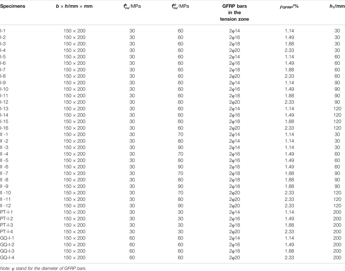
TABLE 1. The main parameters of specimens.
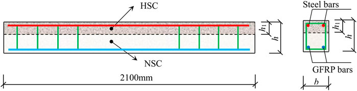
FIGURE 1. Reinforcement mode of specimens.
The linear elastic model was adopted as the constitutive model of GFRP bars, as shown in Figure 2. εfu and ffu represented the ultimate tensile strain and ultimate tensile strength of GFRP bars, respectively. The stress–strain relationship expression is shown in Eq. 1, and the mechanical properties of GFRP bars are shown in Table 2.
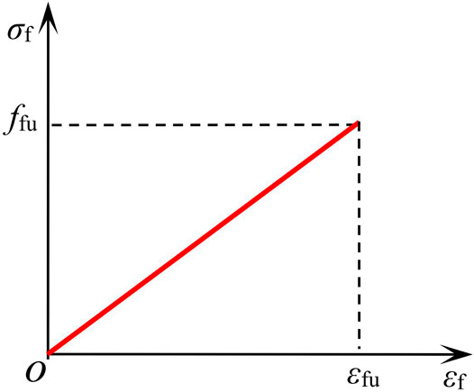
FIGURE 2. Constitutive model of GFRP bars.
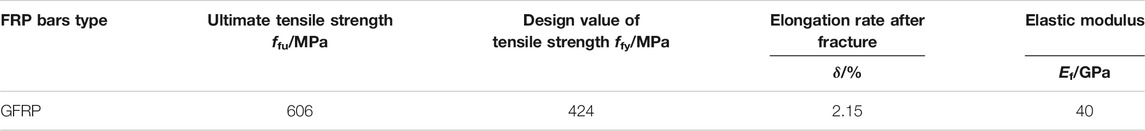
TABLE 2. Mechanical properties of GFRP bars.
where
The ideal double-broken line model was adopted as the elastic–plastic constitutive model of steel bars and stirrups, as shown in Figure 3. εy and fy were the yield strain and yield strength of the steel bars and stirrups, respectively.
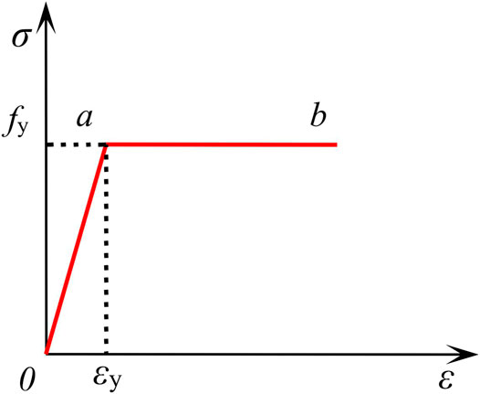
FIGURE 3. Constitutive model of steel bars.
The constitutive model of NSC was given by Teng et al. (Teng et al., 2007), Han (Han, 2007), Code for Design of Concrete Structures (GB 50010-2010, 2010), etc. The constitutive model of HSC was proposed by Ding et al. (Ding and Yu, 2008), and the comparison of different constitutive models is shown in Figure 4. Due to no axial force in the simply supported beam, the restraint effect of stirrups on concrete was not obvious, so the restraint effect was not considered in the concrete constitutive model. By comparison of different constitutive models, NSC adopted the constitutive model proposed in the Code for Design of Concrete Structures (GB 50010-2010, 2010), while HSC adopted Ding’s constitutive model. Plastic damage model of concrete was selected in finite element modeling of ABAQUS (Wang et al., 2019). The constitutive model of HSC was only listed here.
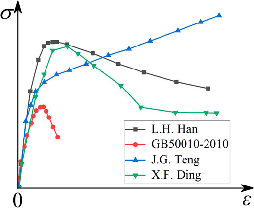
FIGURE 4. Constitutive model of concrete.
The stress–strain relationship of HSC under uniaxial compression:
where
The stress–strain relationship of HSC under uniaxial tension:
where
Based on ABAQUS software, the FEM of the beams consisting of gradient concrete and GFRP bars was established. In order to avoid stress concentration at the loading point, rigid gaskets were set at the ends of beams and three-point loading position. HSC, NSC, and gaskets were established by C3D8R solid element, while steel bars and GFRP bars were established by T3D2 three-dimensional truss element. Steel bars were embedded into concrete by embedded command. Spring element named Spring 2 was established between GFRP bars and concrete to realize bond slip, as shown in Figure 5A. GFRP bars and concrete adopted the same mesh generation, and spring elements were set at coincident nodes in X, Y, and Z directions. In order to simplify the calculation, the spring element which was vertical to GFRP bars was set with greater stiffness, and the calculated force and displacement of the coincidence nodes were written into the INP file of ABAQUS, thus the result considering the bond slip could be gotten. HSC and NSC were connected by binding. Besides, the displacement of gasket at the left end was constrained in X, Y, and Z directions (U1 = U2 = U3 = 0), and the displacement of gasket at the right end was constrained in Y and Z directions (U2 = U3 = 0). Hexahedral element was used for the whole mesh generation. The finite element models of each part and the whole beam are shown in Figure 5.
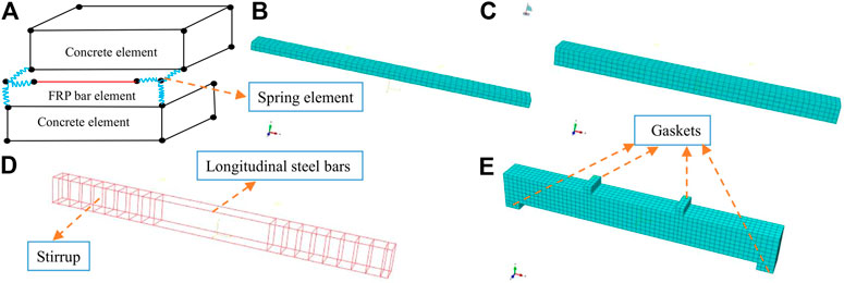
FIGURE 5. FEM of simply supported beams consisting of gratitude concrete: (A) spring element; (B) HSC; (C) NSC; (D) reinforcing cage; (E) overall mesh generation of simply supported beams.
In order to verify the rationality of the finite element modeling, the above modeling method was adopted. Considering the nonlinear constitutive model of materials and the bond slip between GFRP bars and concrete, and introducing the spring element, Five simply supported reinforced gradient concrete test beams (Zhou and Zheng, 2011a) and five simply supported concrete test beams with FRP bars (Zheng, 2008) were selected to carry out finite element simulation. The specific parameters of specimens are shown in Table 3. By finite element simulation the load–displacement curves of the simply supported beams were obtained. The comparison of the load–displacement curves of tests and simulation is shown in Figure 6.
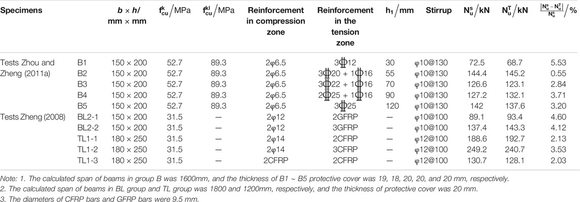
TABLE 3. Main parameters of 10 Specimens.
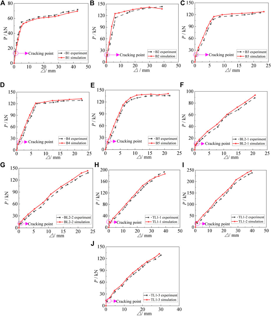
FIGURE 6. Comparison of simulation curves and experiment curves: (A) B1; (B) B2; (C) B3; (D) B4; (E) B5; (F) BL2-1; (G) BL2-2; (H) TL1-1; (I) TL1-2; (J) TL1-3.
It could be seen by comparison that the load–displacement curves obtained by simulation and test were in good agreement, and the rationality of the finite element modeling was verified. The comparative results of the ultimate load (
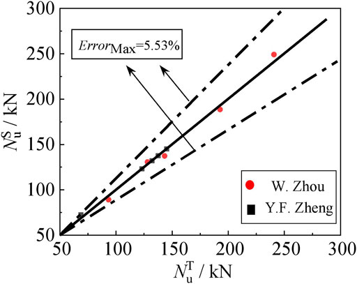
FIGURE 7. Comparison between
The failure process of the simulated specimens was similar to the test. Regarding the simply supported reinforced gradient concrete beams, the HSC in the compression zone was crushed, meanwhile the tensile steel bars yielded, and the failure belonged to ductile failure. The loading process of simply supported beams consisting of GFRP bars were divided into elastic stage and working stage with cracks. The failure patterns of specimens included two failure modes, that is, fracture of GFRP bars in tension zone and crush ability of concrete in compression zone. The stress cloud diagrams of partial specimens are shown in Figure 8.
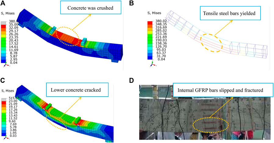
FIGURE 8. Failure modes of B1 and BL2-1 specimens: (A) concrete of simply supported beam B1 was crushed; (B) tensile steel bars of simply supported beam B1 yielded; (C) lower concrete of simply supported beam BL2-1 cracked; (D) internal GFRP bars of simply supported beam BL2-1 slipped and fractured.
The load–displacement curves of simply supported beams with different ρGFRP are compared as shown in Figure 9. The cracks first appear at the bottom of the specimens, and cracking points can be seen obviously in Figure 9. We can see from Figure 9A the ρGFRP of the specimens increases from 1.14 to 2.33%, the cracking load of the specimens keeps almost unchanged, while the ultimate bearing capacity (Nu) increases from 104.01 to 107.43 kN, and the normal-section flexural bearing capacity
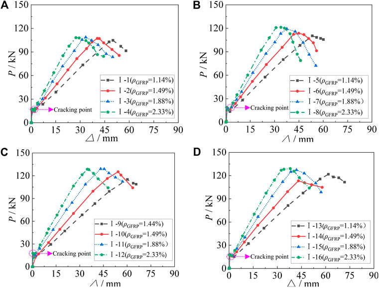
FIGURE 9. Comparison of load–displacement curves of simply supported beams with different ρGFRP:(A)h1 = 30 mm; (B)h2 = 60 mm; (C)h3 = 90 mm; (D) h4 = 120 mm.
The load–displacement curves of simply supported beams with different
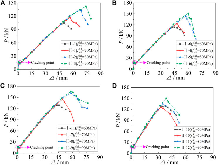
FIGURE 10. Comparison of load–displacement curves of simply supported beams with different
The load–displacement curves of simply supported beams with different h1 are compared as shown in Figure 11. The cracks first appear at the bottom of the specimens, and cracking points can be seen obviously in Figure 11. We can see from Figure 11A that h1 of the specimens increases from 30 to 120 mm, the cracking load of the specimens keeps almost unchanged, while Nu increases from 104.01 to 115.69 kN,
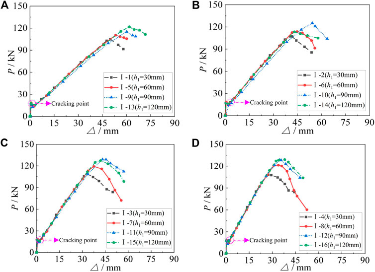
FIGURE 11. Comparison of load–displacement curves of simply supported beams with different h1: (A)ρGFRP = 1.14%; (B)ρGFRP = 1.49%; (C)ρGFRP = 1.88%; (D)ρGFRP = 2.33%.
The load–displacement curves of GFRP simply supported beams consisting of gradient concrete and NSC are compared as shown in Figure 12. The cracks first appear at the bottom of the specimens, and cracking points can be seen obviously in Figure 12. We can see from Figure 12A the cracking load of the specimens keeps almost unchanged, while the Nu increases from 79.85 to 116.01 kN and
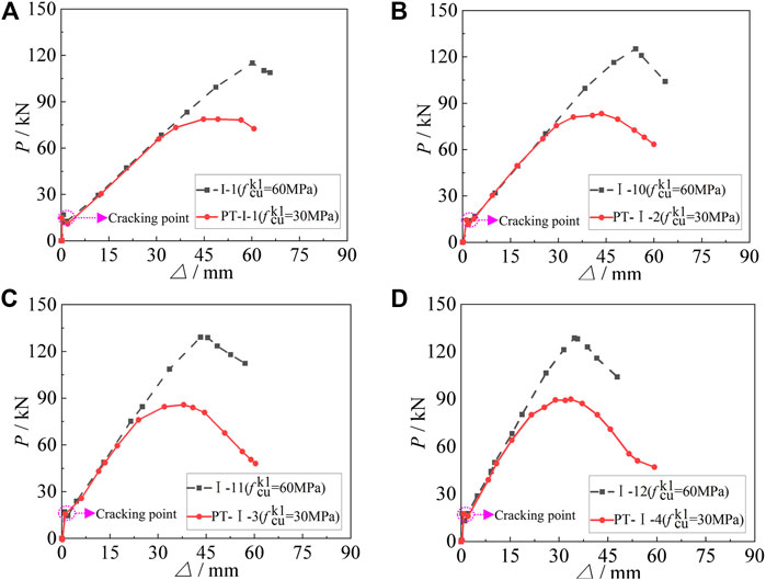
FIGURE 12. Comparison of load–displacement curves between simply supported beams consisting of HSC and NSC: (A)ρGFRP = 1.14%; (B)ρGFRP = 1.49%; (C)ρGFRP = 1.88%; (D)ρGFRP = 2.33%.
The load–displacement curves of GFRP simply supported beams consisting of gradient concrete and HSC are compared as shown in Figure 13. The cracks first appear at the bottom of the specimens, and cracking points can be seen obviously in Figure 13. We can see from Figure 13A compared with the specimens consisting of gradient concrete, the cracking load of full-section HSC is higher and Nu increases from 116.01 to 137.27 kN, and
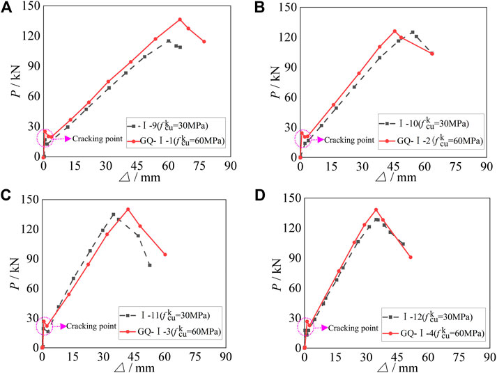
FIGURE 13. Comparison of load–displacement curves of GFRP simply supported beams consisting of gradient concrete and HSC: (A)ρGFRP = 1.14%; (B)ρGFRP = 1.49%; (C)ρGFRP = 1.88%; (D)ρGFRP = 2.33%.
We can see from the parameters analysis and the stress cloud diagram of some specimens (Figure 14) the failure of beams consisting of gradient concrete and GFRP bars is similar to that of beams with NSC and GFRP bars, which is divided into two stages: elastic stage and working stage with cracks. At the initial period of loading, the beams are in the elastic stage, and HSC in the compression zone mainly endures the compressive stress, and load–displacement curves keep straight. With the load increasing, cracks appear in the concrete at the bottom of beams under tension, and obvious inflection points appear in the load–displacement curves. Then the beam enters the working stage with cracks, where the stiffness of the beam is less than that at the elastic stage. Due that GFRP bars are elastic materials, the load–displacement curves of the simply supported beams from cracking to reaching ultimate bearing capacity keep straight, with an increase of load. After reaching ultimate bearing capacity, the curves begin to descend and HSC in the compression zone of simply supported beams is crushed, while the GFRP bars have not yet reached the ultimate strain.
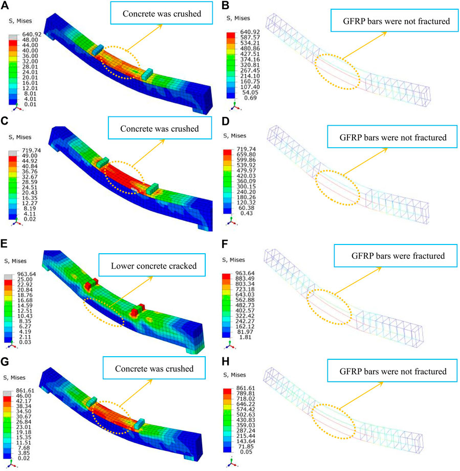
FIGURE 14. Stress cloud diagrams of specimens: (A) stress cloud diagram of concrete for specimen I-1; (B) stress cloud diagram of GFRP bars for specimen I-1; (C) stress cloud diagram of concrete for specimen II-1; (D) stress cloud diagram of GFRP bars for specimen II-1; (E) stress cloud diagram of concrete for specimen PT-I-1; (F) stress cloud diagram of GFRP bars for specimen PT-I-1; (G) stress cloud diagram of concrete for specimen GQ-I-1; (H) stress cloud diagram of GFRP bars for specimen GQ-I-1.
Due to that the stress–strain relationship of GFRP bars is linear; the failure types of simply-supported beams with GFRP bars are different from those of reinforced concrete beams. The failure modes of normal section of beams with GFRP bars include two types: mode I is that GFRP bars are fractured before the concrete is crushed, and mode II is that concrete is crushed before the GFRP bars are fractured, which are brittle failure modes. However, compared with the mode I, the failure signs of beams in the mode II are more obvious. Therefore, it is suggested that the GFRP beams with gradient concrete be designed as over-reinforced beams.
In this study, the following basic assumptions are adopted: 1) plane-section assumption. 2) The concrete in tension zone fails to resist tensile force, which is undertaken completely by GFRP bars. 3) It is confidential for interfacial bond between the GFRP bars and concrete. 4) The neutral axis of the beams is within the section of HSC in compression zone when the beams are damaged. 5) The expression proposed by the Code for Design of Concrete Structures (GB 50010-2010, 2010) is adopted as the constitutive model of HSC.
The stress and strain distribution of simply-supported beams section is shown in Figure 15. According to the principle of concrete stress equivalence, the effective height of HSC in compression zone is obtained as follows:
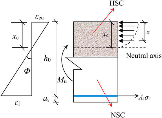
FIGURE 15. Stress and strain distribution of beam section.
According to the balance of force in Figure 15, Eq. 5 can be obtained:
According to the cross-section stress–strain coordination relationship, Eq. 6 can be obtained:
Substituting Eq. 6 into Eq. 5:
By rearranging the terms, we can deduce Eq. 8:
The height of concrete in compression zone can be obtained by solving Eq. 8:
The formula of the normal-section flexural bearing capacity for the gradient concrete beams can be obtained from the moment balance of the section:
where fc and εcu are the axial compressive strength and the ultimate compressive strain of HSC, respectively. Af and Ef are the area and the elastic modulus of GFRP bars in tensile zone, respectively. εf is the tensile strain of GFRP bars when concrete is crushed. β1 is the ratio of the height (x) of the compression zone to the height (xc) of the neutral axis, and its specific values may refer to Code for Design of Concrete Structures (GB 50010-2010, 2010).
According to Eq. 10, the flexural bearing capacity
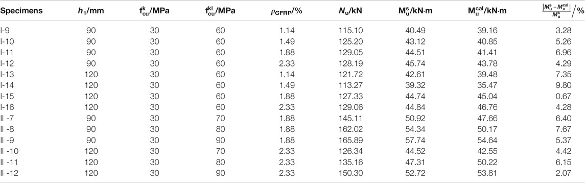
TABLE 4. The comparison of
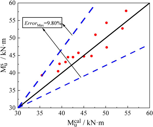
FIGURE 16. Comparison of
Based on the nonlinear constitutive models of materials and considering the bond slip between GFRP bars and concrete, analysis on the flexural behavior of simply supported beams consisting of gradient concrete and GFRP bars with different parameters is carried out by ABAQUS software. The conclusions are drawn as follows:
1) By numerical simulation of five simply supported RC beams with gradient concrete and five simply supported beams with NSC and GFRP bars, the mid-span load–displacement curves of them are obtained. By comparison between simulated results and experimental data, the maximum error is 5.53%, so both agree well. As a result, the rationality of the material constitutive model and method of finite element modeling is verified.
2) With ρGFRP increasing, the flexural bearing capacity of the simply supported beams can improve slightly, while the mid-span deflection decreases significantly. However, with
3) The cracking load of simply supported beams can be improved by using HSC in the whole section of the specimens. However, the use of HSC only in compression zone fails to delay the cracking of simply supported beams. The ultimate bearing capacity of beams with gradient concrete and GFRP bars is about 1.4 times as much as that of beams with GFRP bars and NSC. HSC is adopted only in the compression zone of the beams, which can not only achieve the purpose of significantly improving the normal-section flexural bearing capacity of the beams, but also effectively reduce the engineering cost of the beams.
4) The failure process of simply supported beams consisting of gradient concrete and GFRP bars is similar to that of simply supported beams with NSC and GFRP bars, which can be divided into two stages: elastic stage and working stage with cracks. The failure mode of simply supported beams belongs to compression failure of HSC in compression zone. In order to ensure that the compression failure of HSC happens in practical engineering, it is suggested that this kind of beams be designed as over-reinforced beams.
5) Based on the plane-section assumption, the calculation formula of normal-section flexural bearing capacity of this kind of simply supported beams is proposed through statistical regression analysis. The maximum error between theoretical solution and finite element numerical solution is 9.80%, which can meet the requirements of engineering precision.
The original contributions presented in the study are included in the article/Supplementary Material, further inquiries can be directed to the corresponding author.
JJ: finite element simulation and writing; RZ: finite element simulation and writing; CY: translation; LH: translation; HR: writing; LJ: writing. All authors contributed to the article and approved the submitted version.
All sources of funding received for the research being submitted. The authors are grateful for the financial support received from the National Natural Science Foundation of China (Grant No. 51178087); The Natural Science Foundation of Heilongjiang Province (Grant No. LH 2020E018); Opening Fund for Key Laboratory of The Ministry of Education for Structural Disaster and Control of Harbin Institute of Technology (Grant No. HITCE201908); The Social Science Foundation of Hebei Province (Grant No. HB20GL055), and Northeast Petroleum University Guided Innovation Fund (Grant No. 2020YDL-02).
The authors declare that the research was conducted in the absence of any commercial or financial relationships that could be construed as a potential conflict of interest.
Brian, U., Bennett, T., Sheikh, A. H., and Uddin, M. A. (2017). Large Deformation Analysis of Two Layered Composite Beams with Partial Shear Interaction Using a Higher Order Beam Theory. Int. J. Mech. Sci. 122, 331–340. doi:10.1016/j.ijmecsci.2017.01.030
Ding, X. F., and Yu, Z. W. (2008). Damage Constitutive Model for Concrete under Uniaxial Stress Conditions. J. Chang’an Univ. 28, 70–74. doi:10.19721/j.cnki.1671-8879.2008.04.016
Dong, Z. Q., and Wu, G. (2017). Calculation Method for the Maximum Crack Width of FRP Bar Reinforced Concrete Flexural Member Based on Experimental Data Analysis. China Civil Eng. J. 50, 1–8. doi:10.15951/j.tmgcxb.2017.10.001
Erfan, A. M., Hassan, H. E., Hatab, K. M., and El-Sayed, T. A. (2020). The Flexural Behavior of Nano Concrete and High Strength Concrete Using GFRP. Construction Building Mater. 247, 118664–118675. doi:10.1016/j.conbuildmat.2020.118664
Fan, X. H., Qin, W. H., Xie, P., Ni, L., and Gu, Z. (2020). Shear Force Capacity of Steel-Glass Fiber Composite Bar Reinforced Concrete Beams under Concentrated Load. J. Southeast Univ. (Natural Sci. Edition) 50, 623–629. doi:10.3969/j.issn.1001-0505.2020.04.004
GB 50010-2010 (2010). Code for Design of Concrete Structures. Beijing: China Construction Industry Press.
Han, L. H. (2007). Concrete Filled Steel Tube Structures: Theory and Practice. Beijing: Science Press.
Holschemacher, K., Iskhakov, I., Ribakov, Y., and Mueller, T. (2012). Laboratory Tests of Two-Layer Beams Consisting of Normal and Fibered High Strength Concrete: Ductility and Technological Aspects. Mech. Adv. Mater. Struct. 19, 513–522. doi:10.1080/15376494.2011.556840
Idris, Y., and Ozbakkaloglu, T. (2014). Flexural Behavior of FRP-HSC-Steel Composite Beams. Thin-Walled Struct. 80, 207–216. doi:10.1016/j.tws.2014.03.011
Iskhakov, I., and Ribakov, Y. (2007). A Design Method for Two-Layer Beams Consisting of Normal and Fibered High Strength Concrete. Mater. Des. 28, 1672–1677. doi:10.1016/j.matdes.2006.03.017
Iskhakov, I., and Ribakov, Y. (2008). Two-layer Pre-stressed Beams Consisting of Normal and Steel Fibered High Strength Concrete. Mater. Des. 29, 1616–1622. doi:10.1016/j.matdes.2007.04.013
Magnucki, K., Lewinski, J., and Magnucka-Blandzi, E. (2020). Bending of Two-Layer Beams under Uniformly Distributed Load - Analytical and Numerical FEM Studies. Compos. Struct. 235, 111777–111778. doi:10.1016/j.compstruct.2019.111777
Monetto, I., and Campi, F. (2017). Numerical Analysis of Two-Layer Beams with Interlayer Slip and Step-wise Linear Interface Law. Eng. Struct. 144, 201–209. doi:10.1016/j.engstruct.2017.04.010
Teng, J. G., Yu, T., Wong, Y. L., and Dong, S. L. (2007). Hybrid FRP-Concrete-Steel Tubular Columns: Concept and Behavior. Construct. Building Mater. 21, 846–854. doi:10.1016/j.conbuildmat.2006.06.017
Wang, P., Peng, G., Liu, M. M., Sun, S. P., and Cheng, Z. Q. (2019). Research on Damage Characteristics of Concrete under Biaxial Dynamic Compression Based on Energy Method. Ind. Construction 49, 98–102. doi:10.13204/j.gyjz201905018
Wang, Y. (2018). Flexural Behavior of Concrete Beams Reinforced with FRP Bars. Harbin: Harbin Institute of Technology.
Yang, L. D. (2014). Study on the Shear Performances of Heterogeneous-Overlapped-Composite RC. Xiamen: Huaqiao University.
Zhang, Z. M., Chen, G., and Wang, Z. (2020). Shear Bearing Capacity for Concrete Beams with FRP Reinforcement. J. Shanghai Univ. 26, 301–310. doi:10.12066/j.issn.1007-2861.2027
Zhao, Q. H., Liu, K., Wang, F., and Li, Y. K. (2020). Analyses on Flexural Behavior of GFRP-Reinforced Crumb Rubber Concrete Beams. Acta Materiae Compositae Sin. 11, 1–10. doi:10.13801/j.cnki.fhclxb.20201106.002
Zheng, Y. F. (2008). Experimental Studies and FEM Analysis of Concrete Beams Reinforced with FRP Bars. Jinan: University of Jinan.
Zhou, W., and Zheng, W. Z. (2012). Analysis of Ultimate Load-Capacity for Reinforced Gradient Concrete Beams Consisting of Normal and High Strength Concrete. J. Harbin Univ. Technol. 44, 17–22.
Zhou, W., and Zheng, W. Z. (2011b). Flexural Crack Width Calculation Method for Reinforced Gradient Concrete Beams of Normal and High Strength Concrete. China Civil Eng. J. 44, 42–49. doi:10.15951/j.tmgcxb.2011.12.014
Keywords: GFRP bars, simply supported beams with gradient concrete, constitutive model, finite element model, flexural bearing capacity
Citation: Ji J, Zhang R, Yu C, He L, Ren H and Jiang L (2021) Flexural Behavior of Simply Supported Beams Consisting of Gradient Concrete and GFRP Bars. Front. Mater. 8:693905. doi: 10.3389/fmats.2021.693905
Received: 12 April 2021; Accepted: 03 May 2021;
Published: 25 May 2021.
Edited by:
Huaping Wang, Lanzhou University, ChinaReviewed by:
Xiaomeng Hou, Harbin Institute of Technology, ChinaCopyright © 2021 Ji, Zhang, Yu, He, Ren and Jiang. This is an open-access article distributed under the terms of the Creative Commons Attribution License (CC BY). The use, distribution or reproduction in other forums is permitted, provided the original author(s) and the copyright owner(s) are credited and that the original publication in this journal is cited, in accordance with accepted academic practice. No use, distribution or reproduction is permitted which does not comply with these terms.
*Correspondence: Hongguo Ren, cmVuaG9uZ2d1bzc3MTEyNkAxNjMuY29t
Disclaimer: All claims expressed in this article are solely those of the authors and do not necessarily represent those of their affiliated organizations, or those of the publisher, the editors and the reviewers. Any product that may be evaluated in this article or claim that may be made by its manufacturer is not guaranteed or endorsed by the publisher.
Research integrity at Frontiers
Learn more about the work of our research integrity team to safeguard the quality of each article we publish.