 Kirill Keller
 David Grafinger
 Francesco Greco
95% of researchers rate our articles as excellent or good
Learn more about the work of our research integrity team to safeguard the quality of each article we publish.
Find out more
ORIGINAL RESEARCH article
Front. Mater. , 12 August 2021
Sec. Polymeric and Composite Materials
Volume 8 - 2021 | https://doi.org/10.3389/fmats.2021.688133
This article is part of the Research Topic 2021 Retrospective: Polymeric and Composite Materials View all 8 articles
As printed electronics is evolving toward applications in biosensing and wearables, the need for novel routes to fabricate flat, lightweight, stretchable conductors is increasing in importance but still represents a challenge, limiting the actual adoption of ultrathin wearable devices in real scenarios. A suitable strategy for creating soft yet robust and stretchable interconnections in the aforementioned technological applications is to use print-related techniques to pattern conductors on top of elastomer substrates. In this study, some thin elastomeric sheets—two forms of medical grade thermoplastic polyurethanes and a medical grade silicone—are considered as suitable substrates. Their mechanical, surface, and moisture barrier properties—relevant for their application in soft and wearable electronics—are first investigated. Various approaches are tested to pattern conductors, based on screen printing of 1) conducting polymer [poly(3,4-ethylenedioxythiophene) polystyrene sulfonate (PEDOT:PSS)] or 2) stretchable Ag ink and 3) laser scribing of laser-induced graphene (LIG). The electromechanical properties of these materials are investigated by means of tensile testing and concurrent electrical measurements up to a maximum strain of 100%. Performance of the different stretchable conductors is compared and rationalized, evidencing the differences in onset and propagation of failure. LIG conductors embedded into MPU have shown the best compromise in terms of electromechanical performance for the envisioned application. LIG/MPU showed full recovery of initial resistance after multiple stretching up to 30% strain and recovery of functionality even after 100% stretch. These have been then used in a proof-of-concept application as connectors for a wearable tattoo biosensor, providing a stable and lightweight connection for external wiring.
The investigation of materials and processes for obtaining flexible and stretchable conductors has been driven by both scientific curiosity and technological needs. Recently, it has been boosted by the requirements of novel applications in the fields of flexible/stretchable electronics, wearable sensors/devices, epidermal electronics, biointerfaces, soft robotics, prosthetics, actuators, and energy harvesting devices (Kaltenbrunner et al., 2013; Bandodkar et al., 2015; Liu et al., 2017; Cianchetti et al., 2018; Someya and Amagai, 2019; Yang and Deng, 2019; Yang et al., 2019; Ferrari et al., 2020b).
In principle, an “optimal” stretchable conductor would combine the mechanical properties of a typical elastomer material (such as silicone or natural rubber) with the electrical properties of a purely ohmic conductor, as a metal [e.g., resistivity of Cu, ρ = 15.4 nΩm (Kasap et al., 2017)]. Elastomers show elastic behavior up to very large strain with Young’s modulus within a typical range of E = 10 kPa-10 MPa. They are, however, good insulators, in contrast to metal conductors featuring large electrical conductivity. While the combination of these properties into a single material is very challenging if not impossible, several attempts have focused on materials systems having at least some combined electrical/mechanical features. A variety of approaches have been investigated so far, including conducting polymers and their composites (e.g., interpenetrated networks) with cross-linkable elastomers (Wang et al., 2017; Kayser and Lipomi, 2019); embedding evaporated metals (Au, Ag, Cu) into a stretchable polymer (Kim et al., 2011); nanocomposites of metal/carbon nanoparticles with elastomers (Akter and Kim, 2012; Araki et al., 2016; Yang et al., 2016; Lim et al., 2017; Wu et al., 2017); encapsulated liquid metal (i.e., eutectic GaIn alloys) by fabricating fluidic channels inside an elastomer matrix (Palleau et al., 2013); and printing of graphene/graphene oxide and other carbon-nanomaterials (Dang et al., 2017). In applications, the specific geometry of interconnect circuits (e.g., microfabricated serpentine structures) is often implemented to mitigate the damage effect of imposed strain on conductive tracks.
Most of the aforementioned approaches are based on additive manufacturing, i.e., deposition/patterning of a conductor into/onto a soft and stretchable matrix/substrate. Printing technologies have preeminent importance among these methods, as they can enable the realization of printed conductors over a large area, readily upscalable to high throughput mass production, as required. The specific main challenge in printing a conductor onto a highly deformable elastomeric substrate lies in the matching of the two phases in order to allow reliable functionality and no break or delamination while the material system is flexed or stretched. Matching of these two phases is crucial and challenging at all the different relevant scales, from nano to micro for hybrid nanocomposites up to macroscopic scale for printed or laminated conductors.
A specific application of stretchable conductors, ever-increasing in importance, is to be used as connectors for thin and soft electronic devices, and especially for conformable wearables. With the field of wearable and epidermal electronics growing at a steady pace, novel challenges for material science and engineering are emerging, recently reviewed (Heikenfeld et al., 2018; Gao et al., 2020; Ferrari et al., 2021). Here, combined with the necessary functionality and stretchability, new important requirements can come into play, such as a good match with elastic properties of the skin or other tissues, breathability, compatibility, and high stability at temperatures used for processing of other components.
Different printing methods, mostly inkjet and screen printing, have been proposed for producing flat, lightweight stretchable connectors. Aerosol-jet printing allows abandoning the substrate and producing flat serpentine-shaped stretchable wires on a sacrificial layer which is released upon wetting (Jing et al., 2019). Highly stretchable free-standing self-adhesive PU films produced with the so-called “bubble blowing method” with deposited AgNW show impressive performance; however, it is difficult to control the thickness and produce connectors larger than several cm (Yang et al., 2020).
Screen printing is a powerful method for the deposition of films and microstructures. It uses the mesh screen covered with photo emulsion on which the pattern is formed by masking the desired area before the exposure. After exposure, the untreated area is washed out while everything else remains. In screen printing, ink consists of key materials (e.g., conductive nanoparticles) dissolved in a solvent, often water, alcohols, and glycols. Most of the inks consist of the key component and the viscous carrier, usually a polymer binder or high molecular alcohols. Highly viscous ink is being transferred through the mesh after the pass of the squeegee. Depending on the mesh size, it is possible to obtain features of the specific size and thickness. Screen printing allows producing features with a resolution down to 20–50 μm. The overall quality and resolution of printing also depend on the size of the pattern and the ink composition, viscosity, and wettability. Apart from these “ink” based techniques which are typical of printed electronics, even 3D printing techniques have started to emerge for the production of soft electronics (Tian et al., 2017; Valentine et al., 2017; Yin et al., 2019). However, currently available extrusion-based 3D printers are not yet capable of obtaining conductors with the low thickness required for skin-conformable electronics.
On the other hand, laser scribing is emerging as a new method for the production of conductive materials from dielectric polymers (Ye et al., 2019). Fluence from a laser source operating in the IR or UV range is used to locally induce local heating necessary for photothermal pyrolysis of the polymer precursor. Typically a raster laser scribing is used to operate the patterned pyrolysis into the desired shape of conductors. Depending on the laser power and other rastering parameters (setting the laser fluence, i.e., energy per surface area), the precursor transforms into porous graphitic carbon structures, the so-called laser-induced graphene (LIG). It shows quite good resistivity, huge surface area, and good mechanical properties.
LIG can be readily produced from polyimide (PI) or other flexible (but not stretchable) thermoplastic sheets. Various approaches were proposed to solve the challenge to use LIG in stretchable conductors, including transfer of LIG into PDMS (Rahimi et al., 2015), embedding of PI precursor particles into a cross-linked elastomeric matrix (Parmeggiani et al., 2019), production of LIG from different elastic precursors (Li et al., 2020), or formulation of LIG/PU inks for screen printing (Tehrani et al., 2019). To overcome this issue and apply this material in conformable devices for wearable applications, our group has recently proposed the transfer of LIG onto an adhesive medical polyurethane (MPU) (Dallinger et al., 2020).
Despite the advancements of wearable and tattoo electronics, the wiring of these soft thin devices to external acquisition systems still poses several challenges, especially as regards their mechanical stability and establishment of good electrical contact. Several methods have been proposed to address these challenges (Ferrari et al., 2021), but not all of them can be realized with printing technologies to enable real mass-scale adoption.
In this work, in order to overcome the aforementioned challenges, we investigated various approaches toward the fabrication of reliable stretchable interconnects and external connectors for soft and wearable devices. To this aim, we selected some skin-compatible elastomeric films (silicones, polyurethanes) available in a form of film with different thicknesses and properties. These substrates were first investigated as regards their mechanical, surface, and moisture barrier properties; in the cases where this was deemed relevant, the effect of pre-/post-treatments (plasma, temperature) on their mechanical behavior and wettability was investigated as well.
In Figure 1, the schematics and organization of the present study are summarized. All the elastomeric substrates (silicones, polyurethanes) were first characterized as regards their thickness, surface (roughness, wettability), barrier (water transport), and mechanical properties. Then, stretchable conductors were fabricated by following two different strategies. Two selected candidate elastomeric substrates (silicone, TPU) were used in combination with two different screen-printed conductors: a stretchable silver ink (sAg) and a conducting polymer ink (PEDOT:PSS). A third substrate (adhesive medical polyurethane, MPU) was used as support for laser-scribed porous carbon tracks of Laser-Induced Graphene (LIG). The electromechanical behavior of these stretchable conductors was studied with tensile testing and compared, evidencing the pros and cons of the different approaches.

FIGURE 1. Schematics of the study. Top: illustration of stretchable conductor fabrication processes on selected substrates following two different strategies: screen printing and IR laser scribing. Bottom: summary of the key properties investigated.
In this work the following elastomer substrates were used:
• Silicone films (medical grade silicone rubber, Silpuran® 2030, thickness of 20 and 100 µm) were received from Wacker Chemie AG, Germany.
• Medical polyurethane (MPU) films (Fixomull Transparent, BSN Medical)
• TPU sheets were kindly provided by Mondi Inncoat (Germany) and prepared by A. Kelsch of Mondi Engineered Materials with a manual rod coating on two sides of siliconized 88 g Glassine with a release differential of 1:4.
Weak air plasma treatment was used for cleaning the surface of films from organic residuals and improvement of its wettability to facilitate better film formation during printing on it. TPU and silicone films were treated with plasma with the following parameters: t = 10 s, power = 40% (40 kHz 100 W, Diener Femto Plasma Cleaner, Germany), pressure = 0.3 mbar.
WVTR of TPU and MPU films were measured by covering the open neck of a 50 ml tube filled with water with a film membrane and letting it stay at constant humidity and temperature (RH 17%, 37°C) in a humidity chamber (Espec SH-222, Japan) for 7 days. Every day at the same time, tubes with water were weighed. WVTR was calculated by
where Δm is the mass loss, A is the membrane surface area, and τ is the period of time between two weightings (∼24 h).
Silicone and TPU film thickness were measured with a stylus profilometer KLA-Tencor D-500 (vertical resolution 0.38 Å, lateral resolution 100 nm). There was a minimum of three samples of each film selected and each sample was scanned three times in different parts (with the small stylus force of 0.5 mg). Before measurement, each film was transferred onto a silicon wafer. Because the glue layer of MPU is too soft and sticky for the tip of the profilometer, its thickness was measured with a Leica Wild M3B optical microscope equipped with a camera (minimum resolution 2.4 µm). MPU samples were cut into thin slices and arranged in a u-shape to keep them in place; cross-sectional images were acquired through the microscope camera and analyzed through the camera software.
The roughness of TPU film was extracted from the profilometer scan of the corresponding sample by calculating the arithmetic mean error from the measured profile (calculated by the built-in profilometer software).
Screen printing was performed on a custom manual screen printing press equipped with self-prepared screens. A schematic of screen printing methods is provided elsewhere (Board, 2003). Screens were masked with an array of 42 rectangular tracks (2 × 30 mm). Stretchable conductors were printed with stretchable silver (sAg) (CI-1036 by EMS, United States) and PEDOT:PSS (Orgacon EL-5015 by Agfa) inks. sAg ink was printed using 77 threads/cm and PEDOT:PSS with 100 threads/cm mesh screens. Printing was performed with a rubber squeegee held at an angle around 75° in a single pass on TPU and silicone films. Afterward, films were dried in an oven at T = 110°C for 1 h.
First, LIG was produced by laser scribing of a polyimide (PI) film precursor (thickness 50 μm, Kapton HN sheets, DuPont) attached with biadhesive tape to an aluminum plate (thickness 1 mm). The CO2 IR laser-cutter/engraver (Universal Laser Systems VLS 2.30, p = 30 W, λ = 10.6 µm) equipped with the HPDFO beam collimator (nominal beam size = 30 µm) was used. The following laser rastering parameters were set: power 11%, speed 10%, raster resolution 500 points per inch (PPI), image density 5, and a positive defocusing of 0.7 mm. After laser scribing, the LIG/PI still supported onto the Al plate was placed in the drying oven for 1 h at T = 110–180°C. Then, MPU was laser-cut from the paper side in the form of a stripe (5 × 30 mm). The paper liner was removed, exposing the polyacrylate glue layer which was attached onto LIG/PI and pressed manually. Pressure was applied to allow a good adhesion. The LIG/MPU bilayer was then obtained by peeling off from the PI sheet. SEM images of LIG/MPU were obtained with scanning electron microscope JEOL JSM-6490LV at an accelerating voltage of 10 kV.
Vertical interconnect access (VIAs) holes were laser-scribed on the second layer of MPU (laser parameters: raster mode, power 21%, speed 2.5%, 10 PPI, focus offset 0 mm) that was applied on top of LIG/MPU. The holes (>30 pcs., d ∼ 0.5 mm) were filled with a silver conductive paste (Leitsilber 200) to provide a connection to the LIG sandwiched between two layers of MPU. The sandwich connector was dried for 20 min at 65°C.
Based on some initial tests of printability, three types of samples with different combinations of screen-printed conductors/elastomer substrates were selected for electromechanical investigation. They were sAg on silicone film with t = 100 μm (sAg/silicone 100), sAg on TPU (sAg/TPU), and PEDOT:PSS on TPU (PEDOT:PSS/TPU). Other combinations of substrate/screen-printed conductors were excluded.
All samples were tested with a custom-made setup for electromechanical characterization of samples under tensile strain, described elsewhere (Dallinger et al., 2020). The tensile testing setup was composed of a Load Cell Futek LRF400 (maximum capacity 1.1 N) and an Amplifier Futek IAA100; the load value was read out with an Arduino microcontroller. The stretching speed was set to 0.53 mm/s. The stretching protocol consisted of five repeated cycles of elongation-relax at 5, 10, and 30% and 1 cycle at 100% strain on the same sample. Tests were repeated over at least three samples. A schematic of the actual mechanical cycles is provided in supporting information (Supplementary Figure 1). This device is equipped with a load cell which allows stressing the material at specific strain and (optionally) measuring the resistance at the same time. In the case of electromechanical tensile testing on stretchable conductors’ samples, the following parameters were extracted:
• R0: initial resistance of the sample, before the start of stretching cycles;
• R/R0 relaxed: the change of resistance between the stretching cycles at strain 0%, showing the quality of conductors recovery;
• R/R0 max: resistance change at the maximum strain in the corresponding stretching cycle.
In this work, we compared two kinds of elastomer substrates: a medical grade silicone rubber (two different thicknesses) and two different grades of polyurethane. The medical grade silicone rubber (see details in Materials and Methods) will be called “silicone” in the following, for brevity. It was chosen as an ideal silicone material for applications in stretchable electronics for wearables because it combines many excellent features: transparency, high resistance to heat, chemicals, and radiation, good gas permeability (including the water vapor), good electrical isolation, extremely high elongation at break (450%), good flexibility over a large temperature range (−40-180°C), and biocompatibility, among others (SILPURAN® Datasheet, 2021). Silicone films having a nominal thickness of 20 and 100 μm (±1 μm) were tested in this study. In the following, they will be referred to as silicone 20 and silicone 100, respectively.
Two types of polyurethane films were used: a thermoplastic polyurethane (TPU) film was provided by Mondi Engineered Materials (Austria), while the medical adhesive polyurethane (MPU) is available in commerce (see details in Materials and Methods). TPU consists of a thermoplastic polyurethane sheet supported onto a glassine paper liner on one side (Supplementary Figure 2), from where the TPU film can be simply peeled off. MPU is a commercially available stretchable, transparent, adhesive, breathable elastomeric film for the protection of wound dressing. MPU consists of several layers (see schematics in Supplementary Figure 2): plastic liner and paper carrier are removed prior to use, releasing a thin PU film coated with polyacrylate glue for providing adhesion to the skin. The released TPU film had a thickness of 25 ± 5 μm, while the released MPU had an overall thickness of 54 ± 6 μm (PU layer + polyacrylate glue layer), as determined by stylus profilometry and optical microscopy. One of the key properties of candidate substrates for stretchable conductors is their elastic modulus E, which is defined as
where F is the force, A is the cross section area, and ε is the strain in a tensile testing experiment. It is possible to extract the gradient of the stress from the linear part of the stress-strain curve. Different elastic regimes are observed at different strain ranges, often accompanied by nonlinear behavior, hysteresis, plastic deformation, and creep phenomena. Thus, the aforementioned figure E is often insufficient to properly describe the mechanics of polymer substrates under tensile deformation over the whole strain range of interest. Nevertheless, an estimation of E at different strains [e.g., as estimated from the low-strain region of the stress-strain curve (Figure 2A)] can enable a quick and meaningful comparison among different materials and provide hints for further considerations. Also, comparing the films of Young’s modulus at each cycle (Ec1, Ec2, and so on) during the measurement allows one to quantify the cyclic softening of the elastomer or to evidence the onset of irreversible deformations or damage. A comparison of E for the investigated materials at different strain ranges is provided in Table 1.
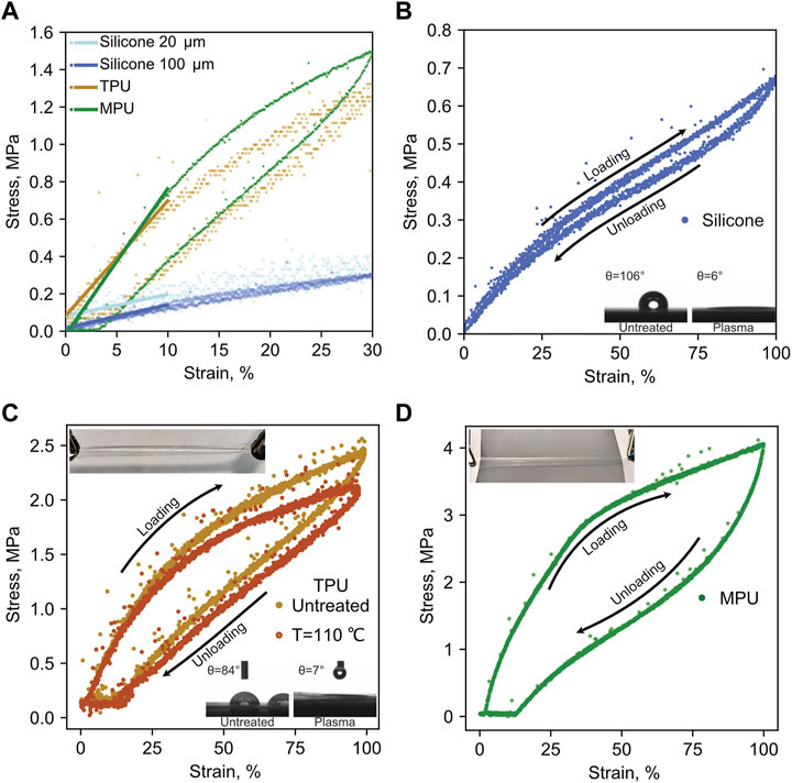
FIGURE 2. (A) Linear approximation of low-strain region (<ε = 10%) of stress-strain curve for all tested films, as extracted from the tensile test at εmax = 30%. (B) Stress-strain plot of silicone 100 film up to εmax = 100%; inset–water contact angles of pristine (untreated) and plasma-treated silicone. (C) Averaged strain-stress plot of pristine and thermally treated TPU up to εmax = 100%; top inset–photo of stretched TPU; bottom inset–water contact angles of pristine (untreated) and plasma-treated TPU. (D) Strain-stress plot of MPU up to εmax = 100%; top inset–photo of stretched MPU.

TABLE 1. Main properties of the studied substrate films.
All the samples were mechanically tested in a tensile setup according to the same protocol (see Materials and Methods). Both types of polyurethanes are stiffer compared to silicone or other typical elastomers (e.g., polydimethylsiloxane (PDMS), E= (0.57–3.7) MPa (Wang et al., 2014)) and show hysteresis in stress-strain curves. Moreover, after a few strain cycles even at low strain, they cannot restore their original length (Figure 2A). Some more data about remaining deformations, energy losses, and static load results of the studied films are presented in Supplementary Information (Supplementary Figure 3; Supplementary Table 1). It is visible from Figure 2A that MPU leads in terms of stiffness. Interestingly, removal of the adhesive with a solvent did not affect the elastic properties to a measurable extent in a low-strain (up to ε = 10%) region (data not shown).
Typical behavior of all the studied films during repeated tensile deformation at εmax = 100% is shown in Figures 2B–D. As anticipated, the low-strain region of TPU and MPU shows a linear behavior, while partial plastic deformation becomes visible for further increasing strain. Elastic moduli of all films were extracted from the linear approximation of the stress-strain half-cycle curve, which are shown in Figure 2A. However, at around ε > 60% for TPU and ε > 40% for MPU, the curves flatten out again, creating the possibility for another linear approximation and extraction of high-strain modulus Ec1 (ε > 70%) (Table 1). Also, TPU showed increased hysteresis compared to MPU, with an energy loss of 0.3 for TPU with respect to 0.19 for MPU after the first cycle. In contrast, silicone shows an almost perfect linear behavior in the range of ε < 30%, even though moderate softening is observed at higher strains. Despite small hysteresis at ε > 30%, silicone shows a complete elastic recovery of initial length upon relaxation. In a static load test, all films were stretched up to ε = 30% and held for 300 s. TPU and MPU were showing an exponential decrease of stress over time, while stress remained constant in the case of silicone (see Supplementary Figure 3). In particular, TPU and MPU showed a recovery time of τ1 ≈ 24 and 21 s, respectively. From this comparison, how the silicone materials show superior mechanical performance compared to polyurethanes emerges clearly, especially as regards elastic behavior over a very large range.
Together with mechanical behavior, another important aspect to take into account for substrates for stretchable conductors is their permeability to gases. Particularly relevant in the case of bioapplications and wearables is the so-called water vapor transmission rate (WVTR) of a polymer film. It is defined as the amount of water vapor transmitted @ T = 37°C through a polymer film membrane sealing a vial with saturated vapor pressure. This quantity obviously depends on the actual thickness of the film, which needs then to be specified, and it is related to its permeability P0. As regards wearables, in order for them to be breathable, it is mandatory that WVTR of substrates is higher than the estimated transepidermal water loss (TEWL) which in an adult amounts on average to 4–8 gm−2h−1 (or around 50–200 gm−2 per day) (Oestmann et al., 1993). Just recently, this so far overlooked property has been considered in designing new wearable devices (Miyamoto et al., 2017), and some systematic investigation and comparison among the used materials provided (Ferrari et al., 2020b). The WVTR of the different investigated materials is reported in Table 1. The values for silicones were taken from the products datasheets (SILPURAN® Datasheet, 2021) while the ones of MPU and TPU were experimentally assessed as described in Materials and Methods. The materials included in this study were selected based also on their breathability, and it is possible to see from the data in Table 1 that all of them can fulfill the requirement of WVTR > TEWL. However, the high permeability to water vapor could be regarded as a drawback in applications other than wearables or in case the used conductors are sensitive/not stable upon exposure to water vapor. In these latter cases, the use of more common silicone elastomers (such as PDMS or other silicone rubber materials) could be recommended, as they are more impervious to moisture. Typically, they show a WVTR of around 0.4 gm−2h−1 (100 μm thick film) (Ferrari et al., 2020b).
Furthermore, we took into consideration the surface properties of the candidate substrates. The morphology and resolution of printed features are greatly affected by the surface roughness and wettability of the substrate. Table 1 displays values of water contact angle θ of the studied films. Silicones have a very smooth but quite hydrophobic surface (θ ∼ 105°). On the other hand, TPU has a rough surface which affects the wettability (θ ∼ 84°); the latter can, in turn, adversely affect the morphology and quality of printed structures. The surface of TPU is rather rough and non-homogeneous, covered with some holes and bumps, probably as a result of lamination processing, as evidenced in optical microscopy and profilometry investigation (Supplementary Figure 4). Roughness is relatively high (on average among the samples of 5 μm). In order to overcome the limitations in printability related to poor wettability, a moderate plasma treatment was used on both silicones and TPU surfaces (Hemmilä et al., 2012). The inset in Figure 2C shows a dramatic change of contact angle of TPU after plasma treatment resulting in almost ideal wetting.
A plasma treatment on polymer films is known to affect their surface, deteriorating their elasticity (stiffening) and making them brittle and, in general, more prone to breaking under repeated mechanical exercise (Ren et al., 2008). Because of the mild plasma condition and short exposure time, enough to activate the surface, the films investigated here did not show any evident damage nor deterioration of their mechanical properties, as assessed by repeating the same mechanical tests on samples after plasma activation. An example is provided in supporting information for silicone samples. From the corresponding stress-strain plots (Supplementary Figure 5), it is clear that plasma treatment did not affect the mechanics of the silicone films in terms of their elastic moduli.
Since most of the screen-printed conductive inks require thermal post-treatment, our further point of investigation was the effect of thermal treatment on the mechanical properties of the TPU film. This is especially relevant in the foreseen application—printing of functional materials and conductors on PU films—since typically one or more thermal treatments are necessary after printing. To this aim, we repeated the same protocol for mechanical testing as seen above on TPU samples after treatment at 110°C for 1 h. Stress-strain plots and respective elastic modulus of untreated, thermally treated, and plasma-treated TPU samples are shown in Supplementary Figure 6. In order to better visualize the results, we averaged measurements for both types of samples (Figure 2C). The overall temperature effect is revealed in a slight softening of the film mostly at high strain (ε > 30%), but it is not impairing its use. The observed softening can be considered acceptable for the aforementioned applications. The thermal stability of silicone substrates is stated in the product datasheet (SILPURAN® Datasheet, 2021) and is not thus further investigated.
In this study, stretchable silver (sAg) and PEDOT:PSS screen printing inks formulations were chosen for deposition of stretchable conductors onto the selected substrates. According to a data sheet provided by the manufacturer, the sAg ink consists of silver nanoparticles embedded into a polyurethane binder matrix, helping it to sustain tensile stress with high recovery of conductivity whereas PEDOT:PSS ink is a dispersion of the conducting polymer PEDOT:PSS nanoparticles in ethanol and diethylene glycol. This principle difference in composition is expected to exhibit also different electromechanical behavior. The main properties of inks are summarized in Table 2. Silicone and TPU films were used as substrates for screen-printed stretchable conductors, and they were plasma-treated prior to printing to facilitate film formation. For silicone films, this was a critical step since without plasma activation sAg droplets transferred through the screen mesh merged into larger domes and disconnected from each other (Supplementary Figure 7). This resulted in deposited tracks with negligible conductivity. A uniform film was instead formed when screen printing on plasma-activated silicone surfaces. The printing on TPU was performed on an uncovered side of the TPU (upper exposed surface, highlighted in red in Supplementary Figure 2). The thermal curing conditions for both inks were set the same in order to avoid different thermal effects on the substrates.
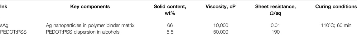
TABLE 2. Main properties of the screen printing inks.
Based on some initial tests of printability, three types of samples with different combinations of screen-printed conductors/elastomer substrates were selected for further investigation. They were sAg on silicone film with t = 100 μm (sAg/silicone 100), sAg on TPU (sAg/TPU), and PEDOT:PSS on TPU (PEDOT:PSS/TPU). Other combinations of substrate/screen-printed conductors were excluded. Despite the fact that sAg and PEDOT:PSS could be efficiently screen-printed onto silicone after plasma activation, the functionality of the PEDOT:PSS/silicone 100 upon stretching was limited to just εmax ∼ 2% (Supplementary Figure 8D), so this was not included in further study at higher strain. A similar behavior was observed on thinner sAg/silicone 20, where the failure happens already at εmax ∼ 1–2% of strain (Supplementary Figure 8C). Because of their adhesive and poorly wettable polyacrylate layer, MPU substrates were not used for screen printing but used for a different transfer strategy involving LIG conductors (see the following subsection).
Figure 3 summarizes and compares the results obtained with the aforementioned combinations of screen-printed conductors/elastomer substrates.
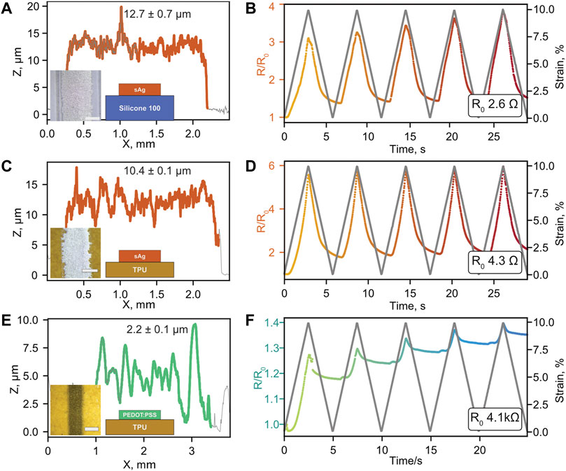
FIGURE 3. Profiles of screen-printed sAg/silicone 100 (A), sAg/TPU (C), and PEDOT:PSS/TPU (E); insets show the optical images of printed tracks and schemes of the printed inks on the various substrates (scale bar corresponds to 1 mm); thickness of each printed pattern estimated by stylus profilometry is specified above each profile. Resistance change over time of sAg/silicone 100 (B), sAg/TPU (D), and PEDOT:PSS/TPU (F) on TPU during five cycles of repeated stretching/relaxation for an applied maximum strain εmax = 10%. Resistance vs. strain plots of the same materials at various εmax is provided in supporting information (Supplementary Figures 8–10).
Figures 3A,B show the structure and electromechanical behavior of sAg/silicone 100 at εmax = 10%. The screen-printed track of sAg has a thickness of 12.7 ± 0.7 μm and a rather rough surface profile, as evidenced in Figure 3A. Except for the first cycle during which the conductor undergoes an irreversible change of its resistance in a relaxed state (R ∼1.5R0), it retains the maximum R/R0 < 4 at max stretching; it almost reversibly restores to values close to the initial R0 upon relaxation. Notably, the sAg/silicone has the lowest resistance in the series (R0 = 2.6 Ω). However, further elongation of sAg/silicone 100 at εmax = 30% led to the formation of cracks in the sAg layer (Supplementary Figure 7) at around ε ∼20%, and, in turn, to an abrupt jump of electrical resistance (loosing of connectivity). Partial connectivity was restored upon relaxation at around 10%, as the cracks closed back during the following cycles (Supplementary Figure 8B). Nevertheless, the composite conductor remained permanently impaired.
As mentioned above, PEDOT:PSS/silicone 100 showed an even worse behavior, with irreversible cracking already at around ε ∼2%. Observed effects probably resulted from incompatible chemistries between the silicone surface and the ink. Even though the ink coverage seems to be fine after plasma treatment, after drying, the film/substrate interface remains weak and easily breakable under applied stress. The hydrophobic nature of the silicone rubber and probable hydrophobic surface recovery over a short time [typically observed in silicones (Everaert et al., 1995)] prevents the good adhesion with the conductive layer of both inks. Moreover, as the profile of sAg on silicone 100 reveals (Figure 3B), the track forms a dome-like shape which also supports the proposed hypothesis.
Figures 3C,F show the results of electromechanical tests for stretchable conductors on TPU films over five cycles of resistance change during stress-relaxation. Very similar to silicones, sAg/TPU had very low R0 (around 4 Ω), given the similar thickness of the track (Figure 3C). sAg/TPU showed a good electromechanical performance, increasing its resistance only by 5–6 times at lower strains, resulting in R = 25 Ω when stretched up to εmax = 10%. The resistance change profile upon stress-relaxation is pretty reversible with a relaxed resistance R/R0 ∼ 2 which almost remained unvaried after the first cycle. This could be explained by a perfect combination of silver filler and polymer matrix of sAg, matched with TPU, which assures the reversibility of the process. Moreover, it should be noted that, given the results of static tests provided in Supplementary Figure 3, part of the resistance change after relaxation is ascribable to incomplete mechanical relaxation of TPU in the experimental timescale. Indeed, the actual stress/relaxation cycles imposed in these tests are too fast compared to the dynamics of the elastomer, having a relaxation time constant of around 24 s.
Nevertheless, during further tensile testing at εmax = 30% a breakage was observed, resulting in failure of the conductor for ε > 20%, as observed for sAg/silicone. Similarly, a partial recovery of connectivity is restored upon relaxation for ε < 10%. Overall, the electromechanical behavior of sAg on both silicone 100 and TPU can be considered very similar, apart from the difference in the elastic modulus of the two materials (Table 1).
Some differences among substrates were instead evidenced in the case of PEDOT:PSS. In contrast to sAg, PEDOT:PSS/TPU has much higher initial resistance (around 3.5–4 kΩ vs. 4 Ω for sAg/TPU). This is expected for the PEDOT:PSS layer, given its smaller thickness (Figure 3E; ∼2.2 vs. ∼12 μm of sAg) and its intrinsic lower conductivity (Figure 4). This double-fold effect is reflected in the different sheet resistance of the two screen-printed materials (Table 2). The resistance of PEDOT:PSS/TPU increased to around 1.4R0 upon five consecutive cycles of stretching to εmax = 10% (Figure 3F). After the first most destructive cycle, the resistance rose by ∼27% and was restored only by a third during relaxation. However, a continuous degradation of the performance after each cycle was observed. New cracks were formed at each subsequent stretch cycle, leading to a steady increase of R with an increase of repeating cycles. More strain cycles led to further degradation; however, the gradient of this change decreased over the number of cycles and reached an R/R0 = 3 and 15 for εmax = 30 and 100%, respectively (Supplementary Figures 9). This can be explained by irreversible crack formation inside the printed track since the used inks consist only of PEDOT:PSS dispersion with viscous additives and no stretchable polymer binders are used. As visible in Supplementary Figures 10, after new maximum stretching at a certain εmax was achieved (with new R0 upon relaxation) any further stretch at ε < εmax did not perturb the resistance, as no new cracks are formed. However, even after repetitive stretching at εmax = 100%, the PEDOT:PSS/TPU remained functional, with the maximum resistance around 450 kΩ at maximum stretch (εmax = 100%) and R0 (relaxed, ε = 0) of around 320 kΩ.
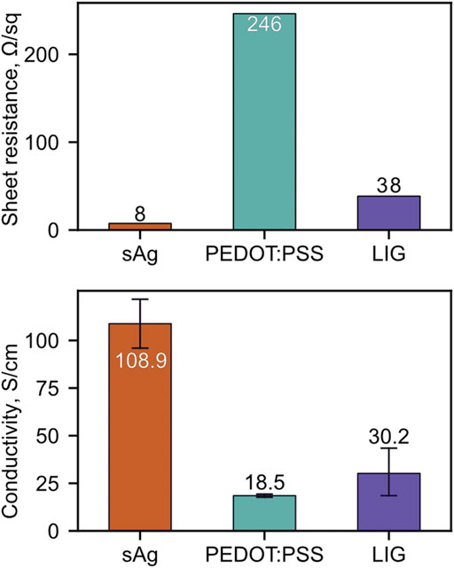
FIGURE 4. Sheet resistance (top) and conductivity (bottom) of the various materials investigated for stretchable conductors: sAg, PEDOT:PSS, LIG. Standard deviation of sheet resistance for all samples is less than 1 Ω. Laser-induced graphene as stretchable conductor.
This behavior of PEDOT:PSS tracks differs very much from the above-described one of sAg on the same TPU substrate. Moreover, these experiments identified an even more striking difference among PEDOT:PSS tracks screen-printed onto silicone and TPU. The difference in behavior, apart from the plastic deformation of TPU stripes, is caused by intrinsic features of printed material. PEDOT:PSS ink is a dispersion of polymer nanoparticles which forms a thin, planar, conformal structure on top of the substrate, better tolerating any partially irreversible destruction under tensile stress. The PEDOT:PSS layer is 5 times thinner than sAg ink and adapts conformally to the high roughness of the film, as visible in the profile reported in Figure 3E.
On the other hand, sAg ink consists of silver particles dispersed in a polymer binder matrix which tends to restore its original shape upon relaxation, but only over a limited range of elongation. In this case, a large resistance change is observed upon stretching, which is however quite totally recovered upon relaxation. This property could be interesting for realizing strain gauges, as done recently with other materials on top of similar substrates (Jang et al., 2019; Shaker et al., 2019).
It can be observed from both optical microscope pictures and profiles (Figure 3) that the edges of printed tracks are uneven and wavy, which is related to the quality of the used screen. The actual width of the PEDOT:PSS track is wider than the nominal (∼2.2 mm) and thinner compared to the stretchable silver one. The roughness of the TPU film is larger than the average thickness of the printed layer which leads to a very inhomogeneous track profile and even holes inside a line which results in worse electric properties. sAg tracks look much better, since the thickness is 5 times higher, and their roughness is not much affected by the substrate roughness. The width is close to nominal (∼1.95 mm).
Laser-Induced Graphene tracks were first scribed into a polyimide (PI) precursor sheet and then transferred onto MPU with a procedure described in the experimental section and similar to (Dallinger et al., 2020).
The laser rastering process responsible for photothermal pyrolysis resulted in tracks of the so-called “porous LIG” (LIG-P) characterized by a 3D porous structure with a thickness of around 8–10 μm (Dallinger et al., 2020), embedded into the PI sheet. The MPU film was attached to the PI sheet letting the polyacrylate glue layer adhere to the exposed LIG surface and then peeled off. A SEM picture of the porous LIG structure embedded into MPU is provided in Figures 5E,F. In Figure 4, the sheet resistance and conductivity values of LIG are provided for comparison with printed conductors. However, it is important to note that LIG is a porous material; therefore, the conductivity of LIG, as calculated with an average thickness of the porous layer containing voids, is certainly underestimated.
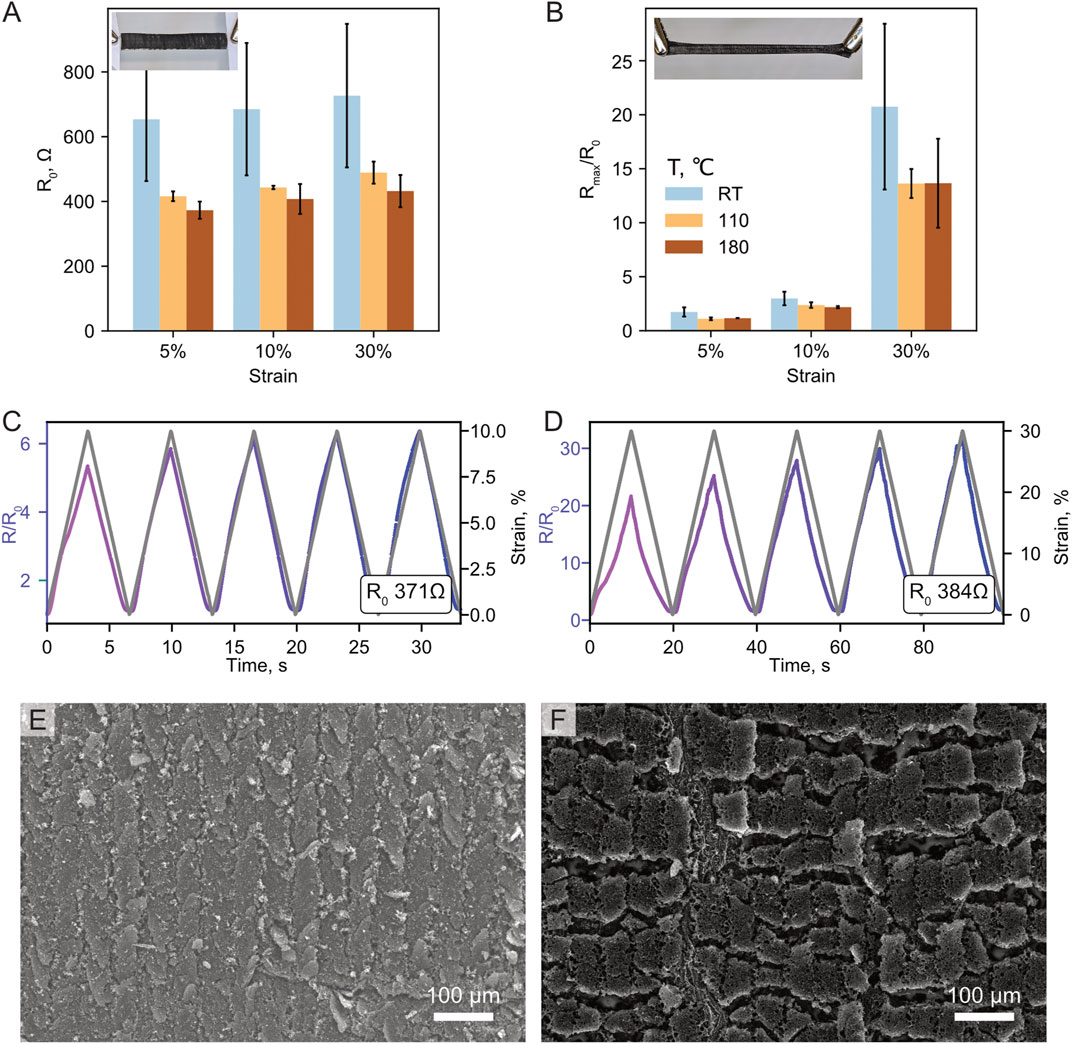
FIGURE 5. Effect of thermal annealing treatment on LIG/MPU initial resistance R0. Comparison of no annealing (T = RT), annealing at T = 110, 180°C for 60 min (A) (inset: LIG/MPU in relaxed state) and resistance change at maximum strain Rmax/R0(B) (inset: LIG/MPU manually stretched to ε ∼ 100%). Resistance change of LIG/MPU composite at εmax = 10% (C) and εmax = 30% (D) for a sample with annealing at T = 110°C; SEM image of the relaxed (E) and stretched (F) LIG/MPU.
Based on some initial investigations not reported here, it was found that a further thermal treatment on LIG before transfer to LIG/MPU could affect its final electromechanical properties, probably caused by a better transfer yield. For this reason, the effect of thermal annealing operated on LIG supported on PI at two different temperatures on the final performances of LIG/MPU stretchable conductors was investigated. On PI, we have not observed any changes in resistance (data not shown). However, a resistance change of transferred LIG with the temperature was observed (Figures 5A,B). A significant change is clearly visible in both R0 and Rmax/R0 ratio at 110°C but almost no change with subsequent heating up to 180°C. Probably, the temperature causes thermal expansion in the underlying PI and facilitates the transfer of the LIG onto MPU.
In Figures 5C,D, the electromechanical performance of LIG/MPU at εmax = 10 and 30% is displayed. The initial resistance R0 is not as low as the one of sAg printed tracks, but one order of magnitude lower than PEDOT:PSS conductor. Moreover, after each strain cycle, the LIG/MPU restored its initial resistance quite closely. At moderate strains (up to 10%), the LIG/MPU stretchable conductor showed much more predictive and reproducible resistance change between the cycles, except for the first cycle where some little irreversible changes were observed, mainly caused by plastic deformation of the MPU substrate discussed above. Another interesting feature of the LIG/MPU in contrast to the other conductors investigated in this study is the reversible restoring of functionality after connection failure at high strain (see Supplementary Figure 11). During elongation up to εmax = 100%, the failure occurred at around ε = 50% (higher than in previous cases discussed so far); connection failure was evidenced by the abrupt jump of resistance to MΩ range. During the subsequent relaxation, at around ε = 40%, the connection was restored and the resistance went back to a value comparable to the ones measured before the stretching. This interesting behavior is probably due to the peculiar structure of LIG. The porous nature of the LIG-flakes embedded into the glue layer of MPU promotes the formation of connection sites between the randomly distributed sheets of graphene which allows extending the strain range of operation and the lifetime of the stretchable conductor under repeated exercise [repeated stretching of LIG/MPU for 200 cycles at εmax = 30% showed stable performance of the stretchable conductor; please refer to supporting information of (Dallinger et al., 2020) for details].
One of the goals of this study was to identify materials and strategies to fabricate stretchable connectors for wearable biosensors, such as temporary tattoo electrodes (TTEs) (Ferrari et al., 2018; Ferrari et al., 2020a). TTEs are ultrathin, soft, and skin-conformable electrodes used for electrophysiological recordings on skin: electromyography (EMG), electrocardiography (ECG), electroencephalography (EEG), and bioimpedance measurements (Taccola et al., 2021). TTEs were printed with PEDOT:PSS which acts as a sensing material; its properties, fabrication, and different applications were profoundly discussed in a recent review (Ferrari et al., 2020b). These unperceivable biosensors allow for long-term recordings with exceptional ease of transfer and maximum comfort for the user, while showing signal acquisition performances comparable to state-of-the-art Ag/AgCl electrodes. Due to their ultralow thickness, they require an interface connection thin enough to not mechanically affect the temporary tattoo film and stretchable to compensate for stresses caused by the wiring to external amplification and acquisition devices. As evidenced in previous studies, the interface from soft ultraconformable tattoo film (typical thickness of around 500 nm, closely adhering to the skin) and the heavy and rigid macroscopic external wiring (detached from skin) is the place where a failure of connection or irreversible damage/breaking can most likely occur. This is due to the mismatch of mechanical properties and concentration of mechanical stress. Several strategies have been adopted, including printed PEDOT:PSS flat connectors on polyethylene naphthalate (PEN)/polyimide sandwich structures and 3D printed plastic clamps (Ferrari et al., 2020a), or printed Ag serpentine lines and a magnetic docking system (Taccola et al., 2021). However, none of these strategies relied on a truly soft, stretchable, lightweight connector.
Based on lessons learned in the investigation of elastomers and stretchable conductors reported in previous sections, we developed a novel design of a stretchable lightweight connector for the TTEs. As a proof of concept for application, a “sandwich” connector was assembled based on a LIG/MPU layer encapsulated with the MPU layer on top (see Figure 6). In the top layer of MPU, several little holes were laser-cut on both tracks of the sandwich. These little holes acted as vertical interconnect access (VIA) for insulated conductive tracks. The VIAs were then filled with a silver paste creating a robust connecting pad, suitable for wiring to external devices. Each hole has a size of ∼0.5 mm, so paste could freely fill the formed channels and intermix with the LIG porous structure. The VIAs provided a perfect electrical connection with the insulated LIG at the same time protecting its fragile porous structure from degradation. Furthermore, these connectors are currently tested in sEMG measurements, giving a good signal and stable comfortable coupling with TTE on the skin.
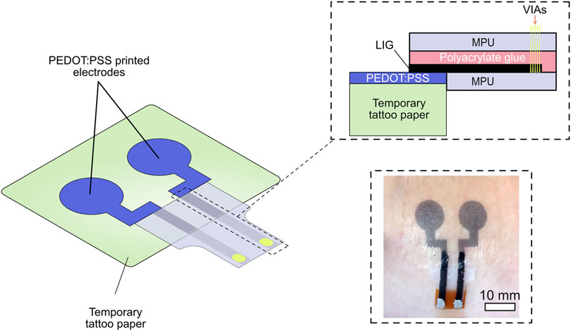
FIGURE 6. Scheme of “sandwich” connector and VIAs based on LIG/MPU and photo of printed TTEs for electrophysiological recordings on skin.
In this work, we have compared several types of stretchable connectors, including screen-printed conductors on silicone and polyurethane substrates and composite material based on laser-scribed graphene LIG embedded into a medical polyurethane adhesive. The mechanics of substrate films was investigated, revealing the viscoelastic behavior of PU films compared to the almost perfect reversible elasticity of silicone films. However, in terms of electromechanical performance, stretchable conductors on silicone showed the worst results. Poor ink to surface interaction, very weak adhesion, and low conformability of ink material to the substrate lead to irreversible crack formation even at a low level of stress despite surface modification. On the other hand, sAg/TPU showed better results, giving more reliable conducting structures, however only at moderate levels of stress. PEDOT:PSS/TPU showed better performances, being the only stretchable conductor among the others which is able to sustain elongation up to 100% without complete irreversible breakage of the connection.
LIG/MPU showed a reproducible resistance change between the stretching cycles and was able to restore the conductivity even after the failure of connection at high strains.
The application of stretchable conductors was demonstrated in a proof-of-concept sandwich connector. This design allows isolating the conducting material while providing a robust external connection through VIAs which are able to sustain moderate strain without losing the connection. This type of connector is a promising candidate for connecting the TTE with external acquisition devices for electrophysiological wearable applications.
The raw data supporting the conclusions of this article will be made available by the authors, without undue reservation.
FG and KK conceived the study. Experimental work was carried out mostly by KK and, in part, by DG. The manuscript was written by KK and FG. All authors reviewed and approved the manuscript before submission.
The authors declare that the research was conducted in the absence of any commercial or financial relationships that could be construed as a potential conflict of interest.
All claims expressed in this article are solely those of the authors and do not necessarily represent those of their affiliated organizations, or those of the publisher, the editors and the reviewers. Any product that may be evaluated in this article, or claim that may be made by its manufacturer, is not guaranteed or endorsed by the publisher.
The contribution by Annette Kelsch and Andrea Lackner at Mondi Engineered Materials (Austria) for preparing and providing the TPU films is acknowledged. The authors are thankful to Alexander Dallinger for providing SEM images of LIG.
The Supplementary Material for this article can be found online at: https://www.frontiersin.org/articles/10.3389/fmats.2021.688133/full#supplementary-material
Akter, T., and Kim, W. S. (2012). Reversibly Stretchable Transparent Conductive Coatings of Spray-Deposited Silver Nanowires. ACS Appl. Mater. Inter. 4, 1855–1859. doi:10.1021/am300058j
Araki, T., Mandamparambil, R., Bragt, D. M. P. van., Jiu, J., Koga, H., Brand, J. van. den., et al. (2016). Stretchable and Transparent Electrodes Based on Patterned Silver Nanowires by Laser-Induced Forward Transfer for Non-contacted Printing Techniques. Nanotechnology 27, 45LT02. doi:10.1088/0957-4484/27/45/45LT02
Bandodkar, A. J., Nuñez-Flores, R., Jia, W., and Wang, J. (2015). All-Printed Stretchable Electrochemical Devices. Adv. Mater. 27, 3060–3065. doi:10.1002/adma.201500768
Cianchetti, M., Laschi, C., Menciassi, A., and Dario, P. (2018). Biomedical Applications of Soft Robotics. Nat. Rev. Mater. 3, 143–153. doi:10.1038/s41578-018-0022-y
Dallinger, A., Keller, K., Fitzek, H., and Greco, F. (2020). Stretchable and Skin-Conformable Conductors Based on Polyurethane/Laser-Induced Graphene. ACS Appl. Mater. Inter. 12, 19855–19865. doi:10.1021/acsami.0c03148
Dang, W., Vinciguerra, V., Lorenzelli, L., and Dahiya, R. (2017). Printable Stretchable Interconnects. Flex. Print. Electron. 2, 013003. doi:10.1088/2058-8585/aa5ab2
Everaert, E. P., Mei, H. C. V. D., Vries, J. D., and Busscher, H. J. (1995). Hydrophobic Recovery of Repeatedly Plasma-Treated Silicone Rubber. Part 1. Storage in Air. J. Adhes. Sci. Technol. 9, 1263–1278. doi:10.1163/156856195X01030
Ferrari, L. M., Ismailov, U., Badier, J.-M., Greco, F., and Ismailova, E. (2020a). Conducting Polymer Tattoo Electrodes in Clinical Electro- and Magneto-Encephalography. npj Flexible Electron. 4, 1–9. doi:10.1038/s41528-020-0067-z
Ferrari, L. M., Keller, K., Burtscher, B., and Greco, F. (2020b). Temporary Tattoo as Unconventional Substrate for Conformable and Transferable Electronics on Skin and beyond. Multifunct. Mater. 3, 032003. doi:10.1088/2399-7532/aba6e3
Ferrari, L. M., Sudha, S., Tarantino, S., Esposti, R., Bolzoni, F., Cavallari, P., et al. (2018). Ultraconformable Temporary Tattoo Electrodes for Electrophysiology. Adv. Sci. 5. doi:10.1002/advs.201700771
Ferrari, L. M., Taccola, S., Barsotti, J., Mattoli, V., and Greco, F. (2021). “15 - Ultraconformable Organic Devices,” in In Organic Flexible Electronics Woodhead Publishing Series in Electronic and Optical Materials.. Editors P. Cosseddu, and M. Caironi (Sawston, UK: Woodhead Publishing), 437–478. doi:10.1016/B978-0-12-818890-3.00015-1
Gao, D., Parida, K., and Lee, P. S. (2020). Emerging Soft Conductors for Bioelectronic Interfaces. Adv. Funct. Mater. 30, 1907184. doi:10.1002/adfm.201907184
Heikenfeld, J., Jajack, A., Rogers, J., Gutruf, P., Tian, L., Pan, T., et al. (2018). Wearable Sensors: Modalities, Challenges, and Prospects. Lab. Chip 18, 217–248. doi:10.1039/C7LC00914C
Hemmilä, S., Cauich-Rodríguez, J. V., Kreutzer, J., and Kallio, P. (2012). Rapid, Simple, and Cost-Effective Treatments to Achieve Long-Term Hydrophilic PDMS Surfaces. Appl. Surf. Sci. 258, 9864–9875. doi:10.1016/j.apsusc.2012.06.044
Jang, E., Liu, H., and Cho, G. (2019). Characterization and Exploration of Polyurethane Nanofiber Webs Coated with Graphene as a Strain Gauge. Textile Res. J. 89, 4980–4991. doi:10.1177/0040517519844604
Jing, Q., Choi, Y. S., Smith, M., Ou, C., Busolo, T., and Kar-Narayan, S. (2019). Freestanding Functional Structures by Aerosol-Jet Printing for Stretchable Electronics and Sensing Applications. Adv. Mater. Tech. 4, 1900048. doi:10.1002/admt.201900048
Kaltenbrunner, M., Sekitani, T., Reeder, J., Yokota, T., Kuribara, K., Tokuhara, T., et al. (2013). An Ultra-lightweight Design for Imperceptible Plastic Electronics. Nature 499, 458–463. doi:10.1038/nature12314
Kasap, S., Koughia, C., and Ruda, H. E. (2017). “Electrical Conduction in Metals and Semiconductors,” in In Springer Handbook Of Electronic And Photonic Materials Springer Handbooks. Editors S. Kasap, and P. Capper (Cham: Springer International Publishing), 1. doi:10.1007/978-3-319-48933-9_2
Kayser, L. V., and Lipomi, D. J. (2019). Stretchable Conductive Polymers and Composites Based on PEDOT and PEDOT:PSS. Adv. Mater. 31, 1806133. doi:10.1002/adma.201806133
Kim, D.-H., Lu, N., Ma, R., Kim, Y.-S., Kim, R.-H., Wang, S., et al. (2011). Epidermal Electronics. Science 333, 838–843. doi:10.1126/science.1206157
Li, J. T., Stanford, M. G., Chen, W., Presutti, S. E., and Tour, J. M. (2020). Laminated Laser-Induced Graphene Composites. ACS Nano. 14(7):7911–7919. doi:10.1021/acsnano.0c02835
Lim, J.-E., Lee, S.-M., Kim, S.-S., Kim, T.-W., Koo, H.-W., and Kim, H.-K. (2017). Brush-paintable and Highly Stretchable Ag Nanowire and PEDOT:PSS Hybrid Electrodes. Scientific Rep. 7, 14685. doi:10.1038/s41598-017-14951-3
Liu, Y., Pharr, M., and Salvatore, G. A. (2017). Lab-on-Skin: A Review of Flexible and Stretchable Electronics for Wearable Health Monitoring. ACS Nano 11, 9614–9635. doi:10.1021/acsnano.7b04898
Miyamoto, A., Lee, S., Cooray, N. F., Lee, S., Mori, M., Matsuhisa, N., et al. (2017). Inflammation-free, Gas-Permeable, Lightweight, Stretchable On-Skin Electronics with Nanomeshes. Nat. Nanotechnology 12, 907–913. doi:10.1038/nnano.2017.125
Oestmann, E., Lavrijsen, A. P. M., Hermans, J., and Ponec, M. (1993). Skin Barrier Function in Healthy Volunteers as Assessed by Transepidermal Water Loss and Vascular Response to Hexyl Nicotinate: Intra- and Inter-individual Variability. Br. J. Dermatol. 128, 130–136. doi:10.1111/j.1365-2133.1993.tb15141.x
Palleau, E., Reece, S., Desai, S. C., Smith, M. E., and Dickey, M. D. (2013). Self-Healing Stretchable Wires for Reconfigurable Circuit Wiring and 3D Microfluidics. Adv. Mater. 25, 1589–1592. doi:10.1002/adma.201203921
Parmeggiani, M., Zaccagnini, P., Stassi, S., Fontana, M., Bianco, S., Nicosia, C., et al. (2019). PDMS/Polyimide Composite as Elastomeric Substrate for Multifunctional Laser-Induced Graphene Electrodes. ACS Appl. Mater. Inter. 11(36):33221–33230. doi:10.1021/acsami.9b10408
Rahimi, R., Ochoa, M., Yu, W., and Ziaie, B. (2015). Highly Stretchable and Sensitive Unidirectional Strain Sensor via Laser Carbonization. ACS Appl. Mater. Inter. 7, 4463–4470. doi:10.1021/am509087u
Ren, T. B., Weigel, T., Groth, T., and Lendlein, A. (2008). Microwave Plasma Surface Modification of Silicone Elastomer with Allylamine for Improvement of Biocompatibility. J. Biomed. Mater. Res. A 86A, 209–219. doi:10.1002/jbm.a.31508
Shaker, A., Hassanin, A. H., Shaalan, N. M., Hassan, M. A., and El-Moneim, A. A. (2019). Micropatterned Flexible Strain Gauge Sensor Based on Wet Electrospun polyurethane/PEDOT: PSS Nanofibers. Smart Mater. Struct. 28, 075029. doi:10.1088/1361-665X/ab20a2
SILPURAN® Datasheet (2021).. Available at: https://www.wacker.com/cms/en-de/products/brands/silpuran/silpuran.html (Accessed March 28, 2021).
Someya, T., and Amagai, M. (2019). Toward a New Generation of Smart Skins. Nat. Biotechnol. 37, 382–388. doi:10.1038/s41587-019-0079-1
Taccola, S., Poliziani, A., Santonocito, D., Mondini, A., Denk, C., Ide, A. N., et al. (2021). Toward the Use of Temporary Tattoo Electrodes for Impedancemetric Respiration Monitoring and Other Electrophysiological Recordings on Skin. Sensors 21, 1197. doi:10.3390/s21041197
Tehrani, F., Beltrán‐Gastélum, M., Sheth, K., Karajic, A., Yin, L., Kumar, R., et al. (2019). Laser-Induced Graphene Composites for Printed, Stretchable, and Wearable Electronics. Adv. Mater. Tech. 4, 1900162. doi:10.1002/admt.201900162
Tian, K., Bae, J., Bakarich, S. E., Yang, C., Gately, R. D., Spinks, G. M., et al. (2017). 3D Printing of Transparent and Conductive Heterogeneous Hydrogel–Elastomer Systems. Adv. Mater. 29, 1604827. doi:10.1002/adma.201604827
Valentine, A. D., Busbee, T. A., Boley, J. W., Raney, J. R., Chortos, A., Kotikian, A., et al. (2017). Hybrid 3D Printing of Soft Electronics. Adv. Mater. 29, 1703817. doi:10.1002/adma.201703817
Wang, Y., Zhu, C., Pfattner, R., Yan, H., Jin, L., Chen, S., et al. (2017). A Highly Stretchable, Transparent, and Conductive Polymer. Sci. Adv. 3, e1602076. doi:10.1126/sciadv.1602076
Wang, Z., Volinsky, A. A., and Gallant, N. D. (2014). Crosslinking Effect on Polydimethylsiloxane Elastic Modulus Measured by Custom-Built Compression Instrument. J. Appl. Polym. Sci. 131. doi:10.1002/app.41050
Wu, C., Jiu, J., Araki, T., Koga, H., Sekitani, T., Wang, H., et al. (2017). Biaxially Stretchable Silver Nanowire Conductive Film Embedded in a Taro Leaf-Templated PDMS Surface. Nanotechnology 28. doi:10.1088/0957-4484/28/1/01LT01
Yang, J. C., Mun, J., Kwon, S. Y., Park, S., Bao, Z., and Park, S. (2019). Electronic Skin: Recent Progress and Future Prospects for Skin-Attachable Devices for Health Monitoring, Robotics, and Prosthetics. Adv. Mater. 0, 1904765. doi:10.1002/adma.201904765
Yang, X., Li, L., Wang, S., Lu, Q., Bai, Y., Sun, F., et al. (2020). Ultrathin, Stretchable, and Breathable Epidermal Electronics Based on a Facile Bubble Blowing Method. Adv. Electron. Mater. 6 (11), 2000306. doi:10.1002/aelm.202000306
Yang, Y., and Deng, Z. D. (2019). Stretchable Sensors for Environmental Monitoring. Appl. Phys. Rev. 6, 011309. doi:10.1063/1.5085013
Yang, Y., Ding, S., Araki, T., Jiu, J., Sugahara, T., Wang, J., et al. (2016). Facile Fabrication of Stretchable Ag Nanowire/polyurethane Electrodes Using High Intensity Pulsed Light. Nano Res. 9, 401–414. doi:10.1007/s12274-015-0921-9
Ye, R., James, D. K., and Tour, J. M. (2019). Laser-Induced Graphene: From Discovery to Translation. Adv. Mater. 31, 1803621. doi:10.1002/adma.201803621
Keywords: stretchable conductors, elastomers, screen printing, laser-induced graphene, conducting polymers, wearable electronics
Citation: Keller K, Grafinger D and Greco F (2021) Printed and Laser-Scribed Stretchable Conductors on Thin Elastomers for Soft and Wearable Electronics. Front. Mater. 8:688133. doi: 10.3389/fmats.2021.688133
Received: 30 March 2021; Accepted: 12 July 2021;
Published: 12 August 2021.
Edited by:
Guilherme Mariz de Oliveira Barra, Federal University of Santa Catarina, BrazilReviewed by:
Shanshan Yao, Stony Brook University, United StatesCopyright © 2021 Keller, Grafinger and Greco. This is an open-access article distributed under the terms of the Creative Commons Attribution License (CC BY). The use, distribution or reproduction in other forums is permitted, provided the original author(s) and the copyright owner(s) are credited and that the original publication in this journal is cited, in accordance with accepted academic practice. No use, distribution or reproduction is permitted which does not comply with these terms.
*Correspondence: Francesco Greco, ZnJhbmNlc2NvLmdyZWNvQHR1Z3Jhei5hdA==
Disclaimer: All claims expressed in this article are solely those of the authors and do not necessarily represent those of their affiliated organizations, or those of the publisher, the editors and the reviewers. Any product that may be evaluated in this article or claim that may be made by its manufacturer is not guaranteed or endorsed by the publisher.
Research integrity at Frontiers
Learn more about the work of our research integrity team to safeguard the quality of each article we publish.