 Zhile Han
 Ninghao Wang2
 Xiaohua Jian
94% of researchers rate our articles as excellent or good
Learn more about the work of our research integrity team to safeguard the quality of each article we publish.
Find out more
ORIGINAL RESEARCH article
Front. Mater., 22 April 2021
Sec. Smart Materials
Volume 8 - 2021 | https://doi.org/10.3389/fmats.2021.663926
This article is part of the Research TopicNew Piezoelectric Materials and Devices: Fabrication, Structures, and ApplicationsView all 11 articles
In this study, an ultrasonic phased-array transducer was proposed, which could effectively improve the imaging performance by using 1–3 piezocomposite. The piezocomposite consists of PZT and epoxy, with a pitch of 70 μm, kerf of 20 μm, and thickness of 170 μm. The phased-array transducer has 64 elements; the size of each element is 85 μm × 1.3 mm; the pitch of the transducer is 100 μm; and the kerf between the elements is only 15 μm. To minimize the transducer size, the 1–3 composite uses an encase structure, which connects the upper surface of the composite directly to the flexible circuit board bonded to the lower surface as the ground electrode. The size of the final fabricated transducer is 2 mm × 7.4 mm, and the transducer is mounted on a 9 F (3 mm diameter) catheter, which can bend in four directions and is primarily used for intracardiac echocardiography (ICE). The acoustic and electrical properties of the transducer were tested, including impedance, echo sensitivity, center frequency (9 MHz), bandwidth (BW) (55%), and consistency. Finally, the wire phantom experiments were carried out to demonstrate the spatial resolutions and imaging performance. This study shows that this transducer with compact design and construction can bring higher performance for the single-use disposable ICE catheter.
Intracardiac echocardiography (ICE) has become a widely used imaging tool in the past decades (Hijazi et al., 2009). The visualization of the heart becomes possible due to the application of ICE and ICE has become an indispensable equipment for various percutaneous, interventional, and electrophysiological procedures (Bartel et al., 2014; Enriquez et al., 2018). ICE catheters can be divided into rotational catheters and phased-array catheters (Vitulano et al., 2015). Among them, the phased-array catheter has wider application potential because of its higher frequency range and ability of Doppler and color flow imaging. With the large-scale application of ICE, it is essential to develop a single-use disposable phased-array catheter with excellent performance and low cost (Bartel et al., 2014).
The miniaturized phased-array transducer has a complicated and challenging fabrication process because the pitch and the kerf must be small enough to avoid spurious modes. Currently, many researchers have focused their efforts on the development of miniaturized phased-array transducer (Bezanson et al., 2014; Chiu et al., 2014; Basij et al., 2019; Cabrera-Munoz et al., 2019). The current manufacturing process of the transducer is rather cumbersome. For example, sputtering Au/Cr layer needs to be performed multiple times to connect the ground of array elements (Cannata et al., 2006), and individual element electrodes are separated by removing the gold layer by using photolithography or Cr/Au etching and carefully aligned with the electrode patterns on the flexible circuit (Chen et al., 2014; Chiu et al., 2014), using conductive epoxy to bond the bent ground electrode on the circuit to the matching layer (Cabrera-Munoz et al., 2019). All these extra processes not only increase the cost of the transducer but also cause the instability of the electrical connection.
The active material is another critical restricting factor for the ICE phased-array probe. The piezoelectric ceramic (Cannata et al., 2008; Kim H. H. et al., 2010) and single crystal (Sung Min et al., 2003; Chen et al., 2012; Wong et al., 2017) have been widely used in array transducer applications. However, these two homogeneous materials will bring lateral mode to interfere between phased-array elements (Yang et al., 2012). Besides, the piezoelectric ceramic is hard to fulfill the requirements of high performance for the phased-array probe though it has stable performance and cost effective (Kim K. B. et al., 2010). In addition, the single crystal is limited by its delicate and expensive cost for disposable catheter applications (Luo et al., 2010). At the same time, 1–3 piezoelectric composite has minimum lateral mode interference, increased electromechanical coupling efficiency, and better acoustic matching (Brown et al., 2007). It is more suitable in the application of ICE phased-array probe.
In this study, a high-performance 1–3 composite is employed to realize an ICE 64-element phased-array transducer. The encase structure is adopted to minimize the transducer size and reduce the complexity of the fabrication process. The working frequency of the probe is chosen as 9 MHz to achieve a higher spatial resolution and ensure a penetration depth of at least 10 cm, which can cover most of the applications of ICE (Alkhouli et al., 2018). The design, fabrication, and characterization of the phased array are then presented. The wire phantom imaging experiments are carried out to demonstrate the spatial resolutions and imaging performance.
The 1–3 piezocomposite was processed by the “dice-and-fill” technique; a mechanical cutting saw (DAD3221, Disco Co., Tokyo, Japan) was used to cut kerfs into a piece of bulk piezoelectric ceramic; and the kerfs were backfilled with epoxy. In the 1–3 composite, the generation of spurious resonances within the designed operating bandwidth (BW) should be avoided. To avoid the problems with lateral modes, the pillars in the composite should have a width that is lower than half of the pillar height. The generation of the first two spurious Lamb wave mode frequencies, fL1 and fL2, can be predicted using the following equation:
where υ _phase is the phase velocity in the transverse direction across the piezocomposite and d is the pillar-to-pillar spacing within the composite. The phase velocity in low fractional ceramic-volume composites is predominantly determined by the shear wave velocity of the filler epoxy. To push the lateral modes outside the operating BW of the transducer, the composite in this study is designed with 50 μm height, 20 μm width (Brown et al., 2007), and 51% volume fraction. The composite was finally grounded to a thickness of 170 μm. The PZT-5H (3203HD, CTS [Tianjin] Electronics Company Ltd., Tianjin, China) was chosen as the active material of 1–3 composite because of its wide application and high price–performance ratio. A simulation model was built to analyze the piezoelectric characters of the 1–3 composite material, as shown in Figure 1, a part of the composite material structure was built, and its outer boundary was set as symmetric to simulate the whole characteristics of composite material.
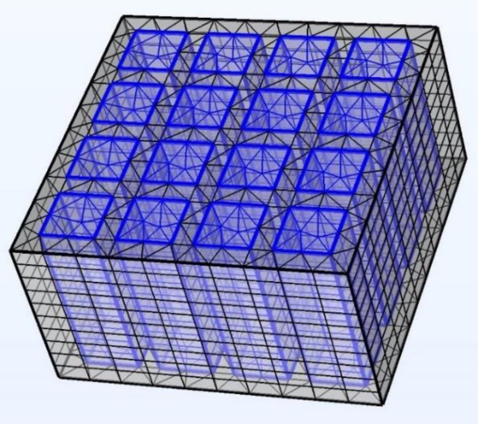
Figure 1. The simulation model of 1–3 piezoelectric material.
For the phased-array transducer with central frequency around 9 MHz, the element pitch should be less than λ (wavelength in water, 167 μm), which is 100 μm in our design, and the kerf is 15 μm. In order to make the distribution of the piezoelectric column in each array element as consistent as possible, the element pitch value needs to be designed to equal cutting kerf plus piezoelectric pillar width (Zhou et al., 2011, 2020; Zhang et al., 2020), and the composite material is diced in a direction parallel to the edge of the pillars. This traditional method limits the design of element size. When the material is diced parallel to the edge of the ceramic pillar, due to the epoxy bumps at the interface between the ceramic pillar and bulk epoxy caused by the differences in the mechanical properties of ceramic and polymers (Cochran et al., 2006; Boonruang et al., 2019), the bumps are easy to cause the fracture of the electrode Au/Cr layer, so a more suitable dicing method need to be designed.
In this study design, to make the distribution of the piezoelectric column in each array element as consistent as possible, it is necessary to cut the composite material along with a specific angle.
The specific angle is calculated as follows:
(1) Select a1 as the initiated centered position and draw a circle with a radius of 100 μm.
(2) Look for points that are most similar to a1. As shown in Figure 2A, point a2 has the same location features as point a1.
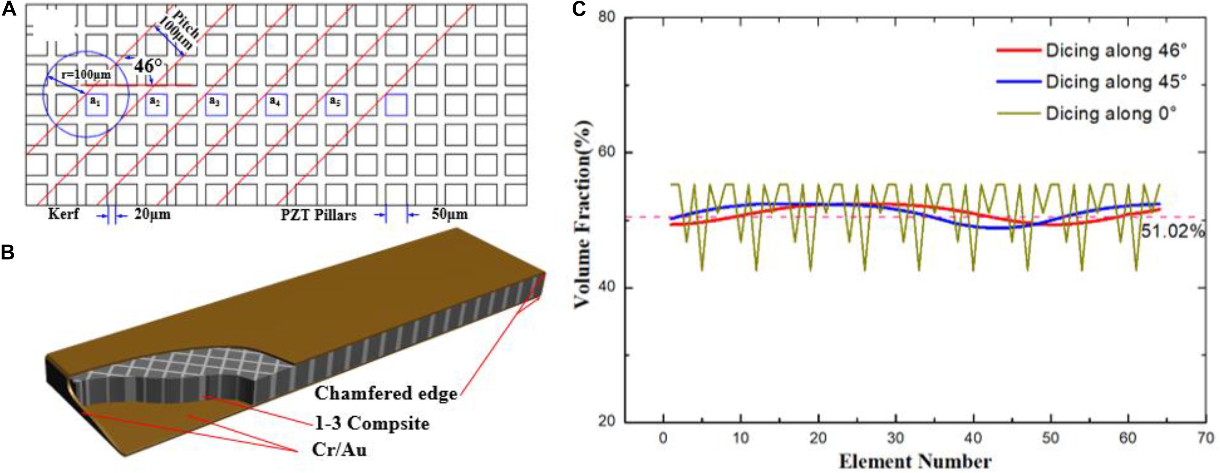
Figure 2. (A) Dicing methods, (B) model of 1–3 piezocomposite, and (C) volume fraction comparison of each element.
(3) Draw a tangent line to the circle along point a2. The angle between the tangent line and the horizontal direction is the specific dicing angle.
It is straightforward that the optimal angle can be calculated as 46°. After dicing the material and sputtering the Au/Cr layers on the surface of the 1–3 composite, the designed material was diced into a size of 1.3 × 7.4 mm, with an encase electrode layer structure, as shown in Figure 2B, which was connected along the short side from the upper surface to the lower surface.
Each element of the transducer has an area of 0.085 mm × 1.3 mm and is composed of several ceramic pillars and epoxy. The consistency of the array elements depends on the active volume of the pillars contained in each array element, and it can be calculated using AutoCAD software (Auto CAD 2012, Autodesk Inc., San Rafael, CA, United States), as shown in Figure 2C. Compared with the dicing method parallel to the edge of the pillar (0°) or the diagonal of the pillar (45°), the current method can achieve higher consistency, with a volume fraction of 50.95% ± 1.61% of piezoelectric ceramic.
The phased-array transducer was fabricated using a novel transducer technology, and it had a total active azimuth aperture of 6.4 mm and an active elevation aperture of 1.3 mm.
As shown in Figure 3, first, both sides of the encase structure of composite were cleaned by applying the acetone and reagent alcohol with a cotton swab, and then the structure was bonded using nonconductive epoxy (Epo-Tek 301, Epoxy Technology Inc., Billerica, MA, United States), to the polyimide matching layer and custom-designed flexible circuit (FPC), which was consisted of a polyimide base material and a layer of copper foil. After cured overnight at 50°C, the dicing process was performed by using a 15-μm width dicing saw from the FPC side and the depth of dicing was set to 0.12 μm into the center of the composite material. Finally, a compound mixed with epoxy resin and tungsten powder was employed as the backing layer; its weight ratio was 3:7; and after removing bubbles by vacuuming, the backing material was poured on the backside of the transducer and cured at 60°C for 12 h. It was cast on the acoustic stack. The Au/Cr layer on the upper surface of the composite as a ground electrode was connected to the FPC board bonded to the lower surface in order to lead out through the traces on the flexible circuit. The array design parameters and material properties are shown in Table 1. The acoustic impedances of the materials were measured through a pulse-echo method (Zhangjian et al., 2020).
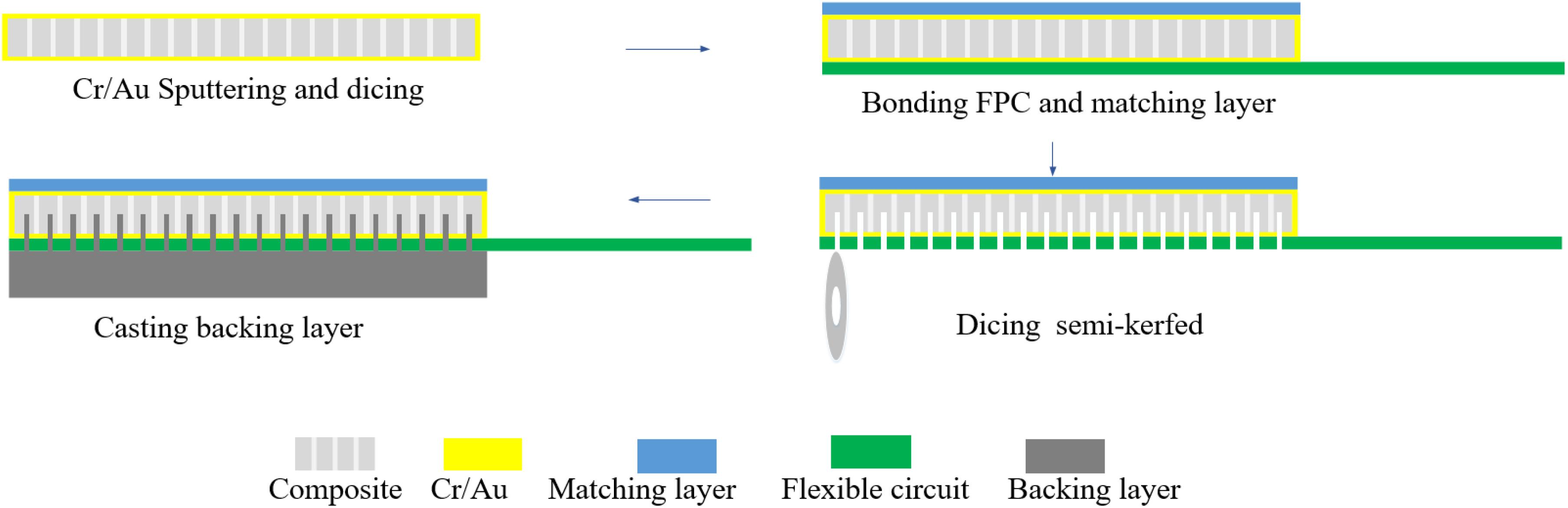
Figure 3. Fabrication process of the phased-array transducer.
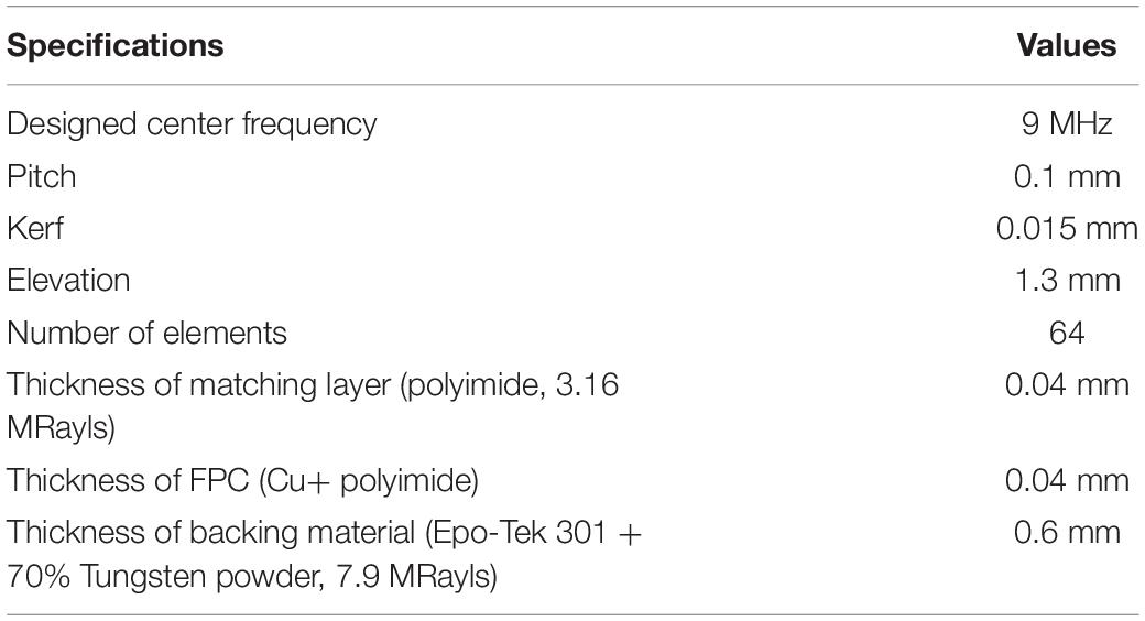
Table 1. Design parameters of the phased-array transducer.
The composite was diced in an oblique direction of 46°, which caused multiple pillars half-cut in each element although the material is composite. However, several phased-array transducers have been designed in many studies with the half-cut technology, and the beam performance test indicated that the focusing and steering ability was satisfactory (Zhang et al., 2011; Bezanson et al., 2014, 2020). Compared with wire bonding the array elements to the thickness dimension of flexible circuit boards or other methods, the acoustic stack with encase structure and the half-cut elements reduced the interconnect size, allowing for significantly reduced cost and complexity of manufacturing.
The acoustic stack was assembled at the distal end of an ICE catheter; the pads on the FPC end were welded to the 48 American Wire Gauge (AWG) coaxial cable inserted inside the catheter, as shown in Figure 4A; and the other end of the cable was connected to the breakout board of an imaging system by a customized connector.
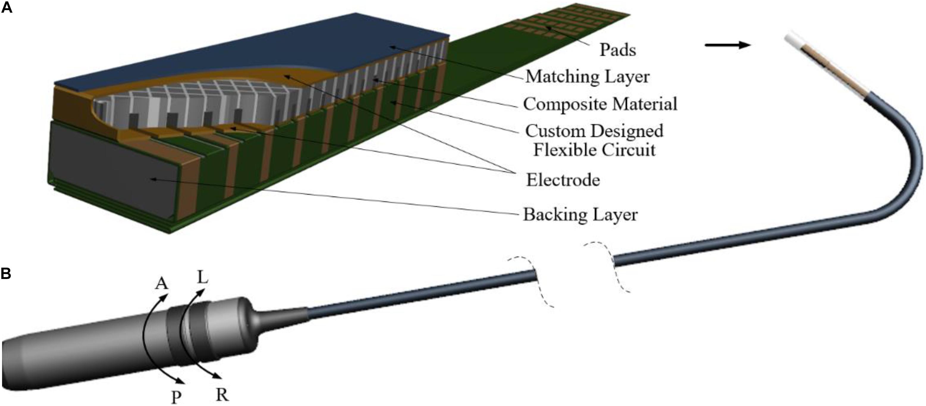
Figure 4. Model of (A) the phased-array transducer and (B) the ICE catheter.
The outside of the transducer except for the imaging window was cast with Pebax 2533 material for medical applications. The custom-designed catheter (ICE, Xinhuajia Technology Co., Shenzhen, China) was a long, thin, flexible multilayer plastic tubes, with four pull wires spaced apart 90° along the cross section connect the distal end to handle, and had an insertable length of 900 mm, as shown in Figure 4B. The catheter was manually manipulated by grasping the catheter handle and actuating each of the four degrees of freedom (left/right and anterior/posterior), and able to bend up to an angle of 160°, with a minimum bending radius of 27 mm.
The fabricated ICE transducer, as shown in Figure 5A, is the structure of 1–3 composite materials under a microscope, and Figure 5B shows a customized flexible circuit board, which is mainly composed of two parts, namely the transducer assembly part and the characteristic detection part, where the latter is used to test the characteristics of the transducer and will be removed in the subsequent process. Figure 5C shows the manufactured transducer, the remaining FPC board can be folded and cast with Pebax 2533 as protection, and the total structural size of the transducer is 3 mm in diameter, as shown in Figure 5D.
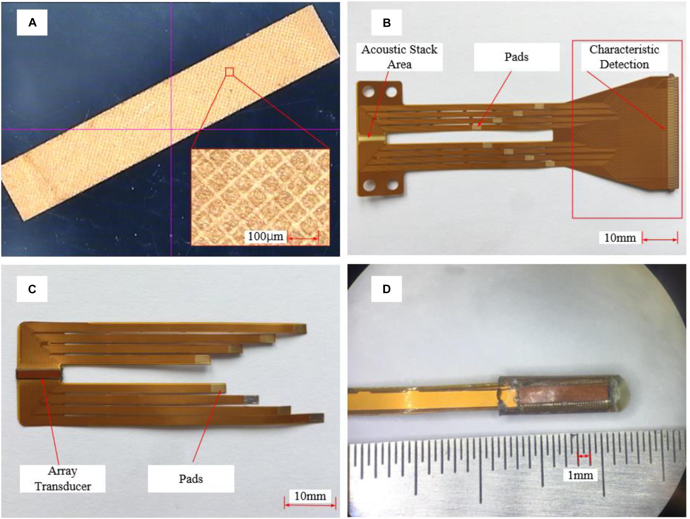
Figure 5. Photograph image of (A) 1–3 composite material, (B) FPC board, (C) fabricated transducer, and (D) probe cast with Pebax.
A bundle of 64 individual 48-AWG micro-coaxial cables with a total outer diameter of 1.9 mm is carefully soldered to the transducer as shown in Figure 6, and the other ends of the cables are divided into four groups where each group is soldered on a custom L-shaped circuit board, which can be connected to a commercial Verasonics Vantage 128 System (Vantage 128, Verasonics Inc., Kirkland, WA, United States).
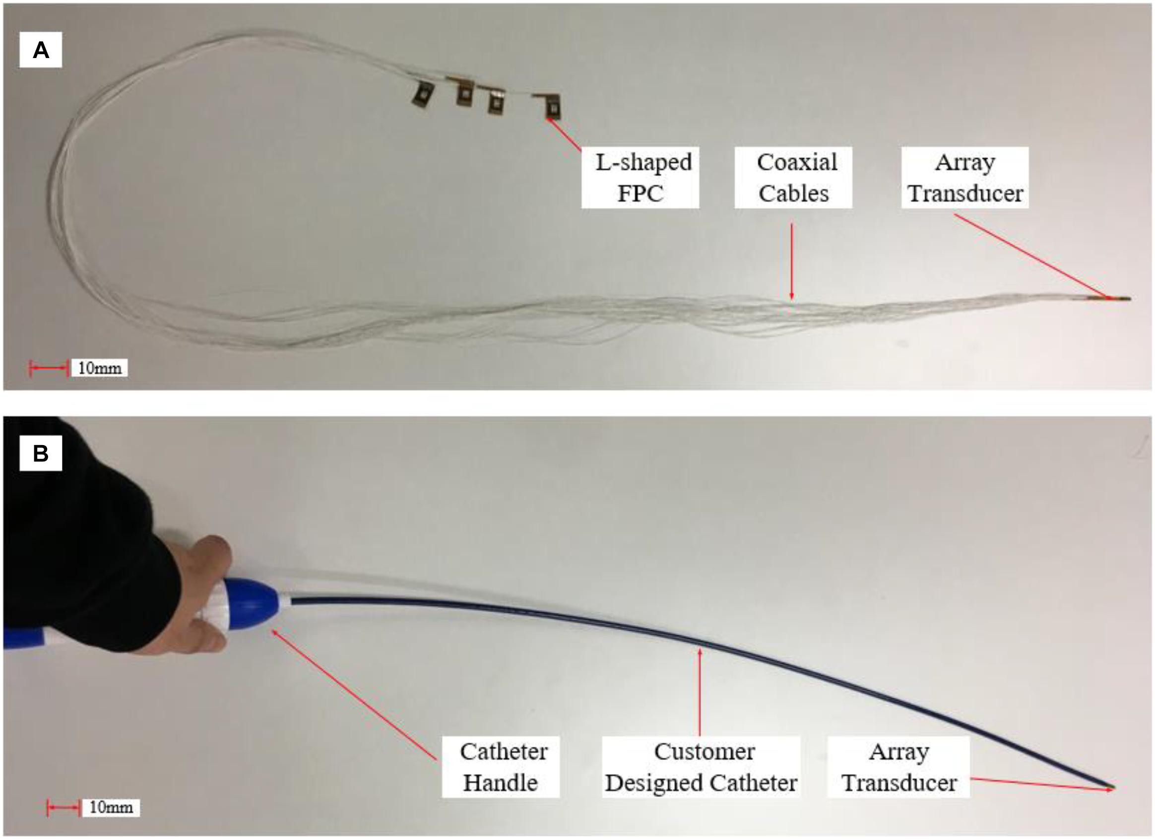
Figure 6. Photograph image of (A) ultrasound probe with cables and (B) ICE catheter.
The simulation result and the test result of the composite material are shown in Figure 7. The simulation impedance curves are almost the same as the measurement result. It can be noticed that the magnitude value of the simulation impedance curve is much larger than the measurement result, and the reason is due to that the area of the simulation model is much smaller than the tested area.
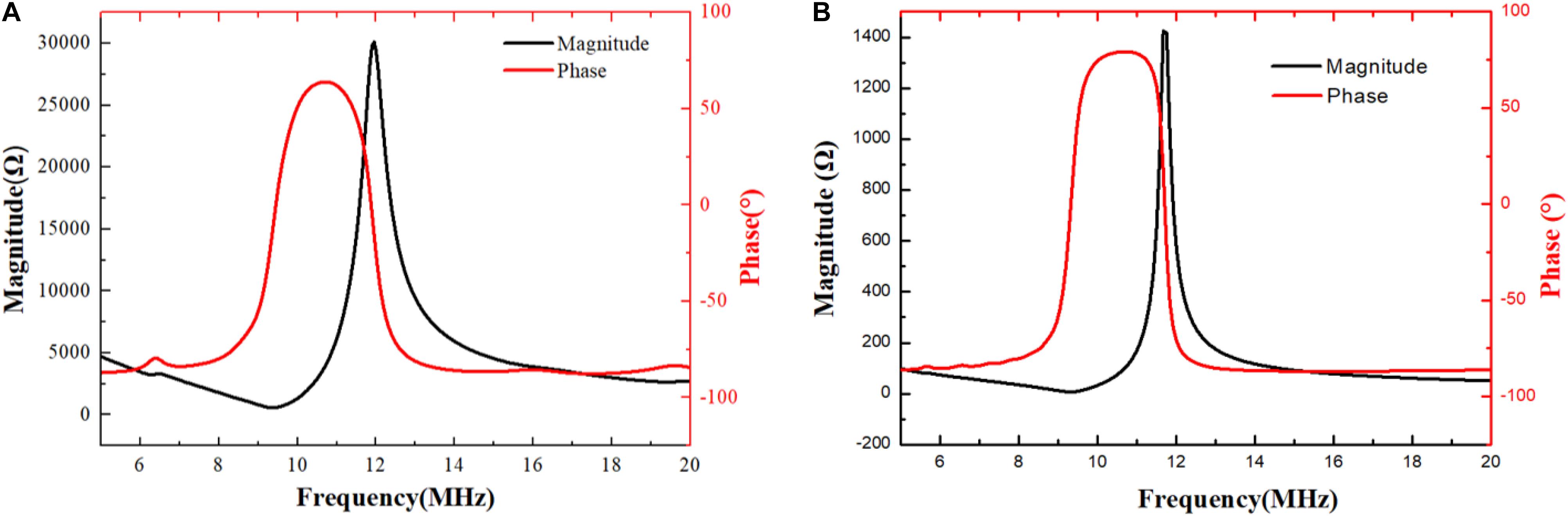
Figure 7. (A) Simulated and (B) measured impedance and phase of 1–3 composite.
According to the measured electrical impedance spectrum, the center frequency of the fabricated 1–3 composite is 10.2 MHz, and its electromechanical coupling coefficient (kt) is 0.66, which is higher than 0.55 of pure PZT-5H (CTS, 2021). Besides, according to the 1–3 composite thickness mode (Smith and Auld, 1991), the main piezoelectric properties of the 1–3 composite including longitudinal velocity, density, and acoustic impedance are listed in Table 2.
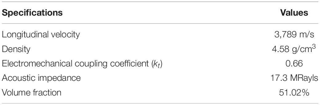
Table 2. Properties of 1–3 piezoelectric composite.
Each of the elements was repolarized in the polarizing fluid under an electric field of 2 kV/cm for 3 min using a high-voltage power supply before testing. Then the electrical impedance was measured using an impedance analyzer (E4991A, Keysight Technologies Inc., Santa Rosa, CA, United States) before connecting each element to the coaxial cable assembly; both the impedance magnitude and phase angle were recorded over the range of 5–15 MHz.
The measured values of all 64 elements are shown in Figure 8, and the average value and SD of electrical impedance at 9 MHz were 288.48 ± 27.24 Ω and 72.35° ± 2.92°, respectively. Since the electrical impedance was measured by connecting each pad on the transducer to the impedance analyzer, a 20-mm homemade electrical probe was used in the test and brought the smaller resonance peak located at around 6 MHz.
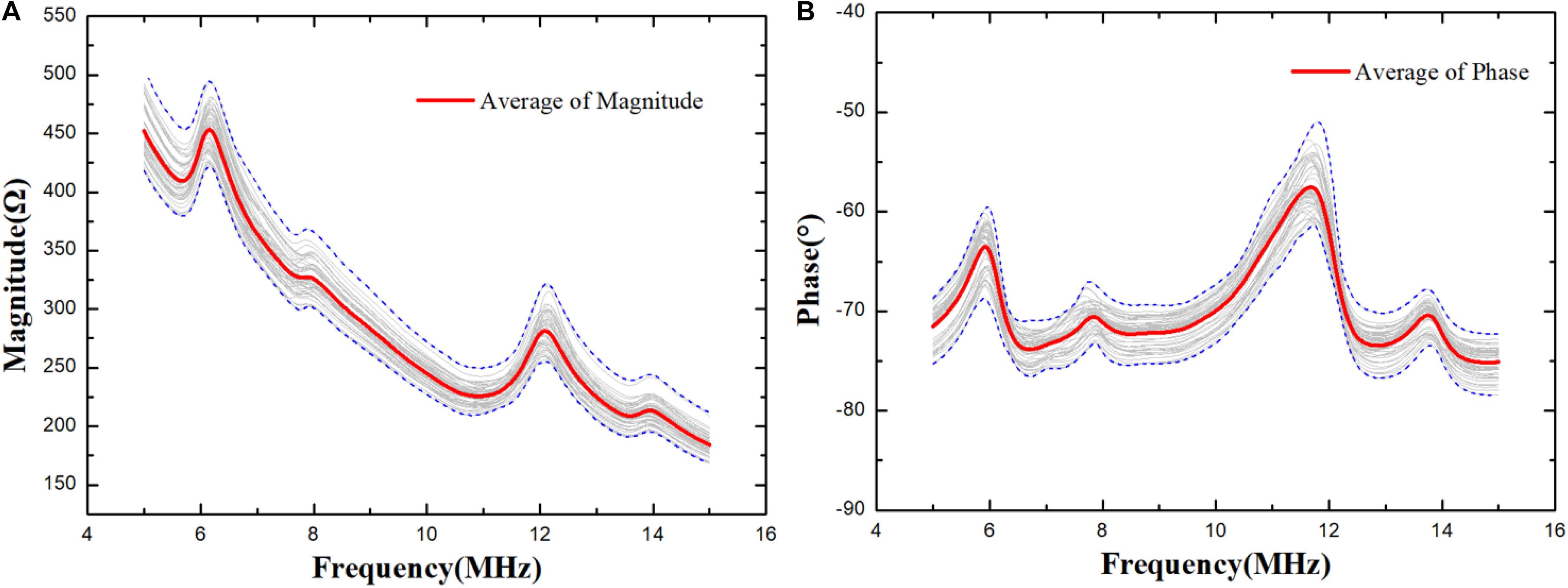
Figure 8. Electrical impedance (A) magnitude and (B) phase as a function of frequency for 64 elements.
After completing the cable welding and fabrication of the catheter, the pulse-echo response was performed in deionized water at room temperature for the characterization. A device (DPR 500, JSR Ultrasonics Inc., Pittsford, NY, United States) with a remote pulser RP-H4 was used to excite the elements of the transducer: the voltage amplitude of the pulser was set as 330 V, the PRF was 200 Hz, and the echo was received by the device with 0 dB gain. The waveforms were recorded and processed by an oscilloscope (DPO5034, Tektronix Inc., Beaverton, OR, United States). Each element was connected in series with a 1.2 μH inductor for impedance matching.
Figure 9A shows the measurement results of a representative array element, and the uniformity of the calculated center frequency (Fc), − 6 dB BW, and peak-to-peak sensitivity of the phased-array transducer are illustrated in Figure 9B, which are about 9 MHz, 55%, and 150 mV, respectively. It can be found that the acoustic performance of the phased array exhibits a good uniformity. In Figure 9A, ringing and bumpy spectrum are observed, and it might be caused by the FPC layer between the backing and composite materials. A single matching layer may also lead to insufficient BW.
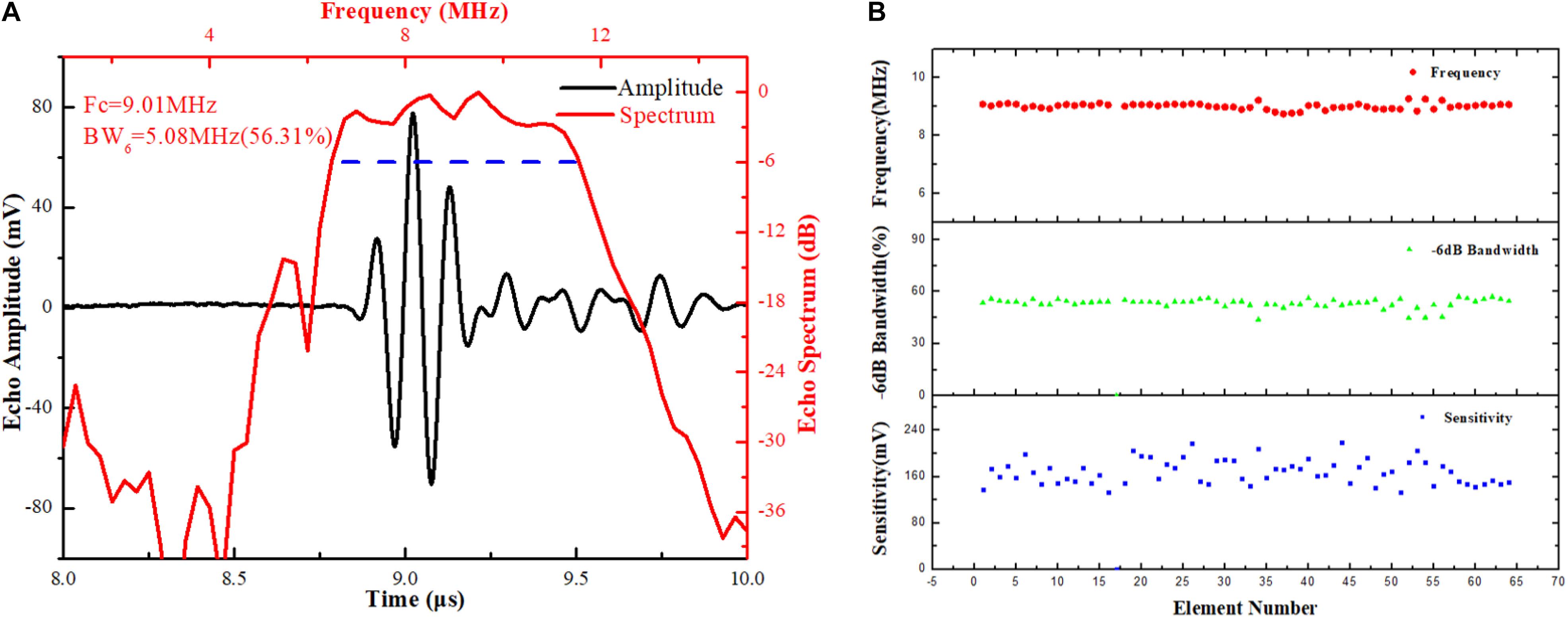
Figure 9. Measured (A) pulse-echo response performance of element 17 and (B) frequency, bandwidth, and sensitivity of the pulse-echo signal for each element.
For the two-way insertion loss (IL) measurement, the transducer was excited with a 5-Vpp, four-cycle sinusoidal tone-burst signal at 9 MHz, and the reflected echo was received from a polished steel reflector. The echo signal (Vo) was measured by the oscilloscope with a 1 MΩ coupling, and the driving signal (Vi) was then measured with a 50 Ω coupling. The measured value was corrected for loss due to attenuation in water (2.2×10⁻⁴dBmm−1×MHz2) and reflection from the steel target (0.6 dB) (Cannata et al., 2006). The IL was calculated using the following equation:
where fc is the center frequency and d is the distance between the transducer and steel reflector. The IL value of the array is measured to be 39.1 dB, which is somewhat higher than other reported transducers, and this might be due to the relatively low g33 coefficient of piezoelectric composite material (Dias and Das-Gupta, 1994). Besides, it is not easy to obtain high sensitivity by monolayer matched layer. The sensitivity can be improved by increasing the piezoelectric volume ratio and adopting multilayer matching.
For the cross-talk measurement, a 5-Vpp, 20-cycle sinusoidal tone-burst signal generated by a function generator (33250A, Keysight Technologies Inc.) was used to excite one representative element (element 23) in the phased array with a frequency range from 3 to 15 MHz in steps of 2 MHz. The voltages across the first, second, and third adjacent elements were measured and the cross talk was calculated as reference (Cannata et al., 2006).
The measured cross talk is shown in Figure 10. As shown in the figure, the maximum cross-talk values at the center frequency were −34.5, −36.4, and −38.9 dB for the first, second, and third adjacent elements respectively. Considering the simplicity of array design and construction, these values are considered satisfactory (Lukacs et al., 2006).
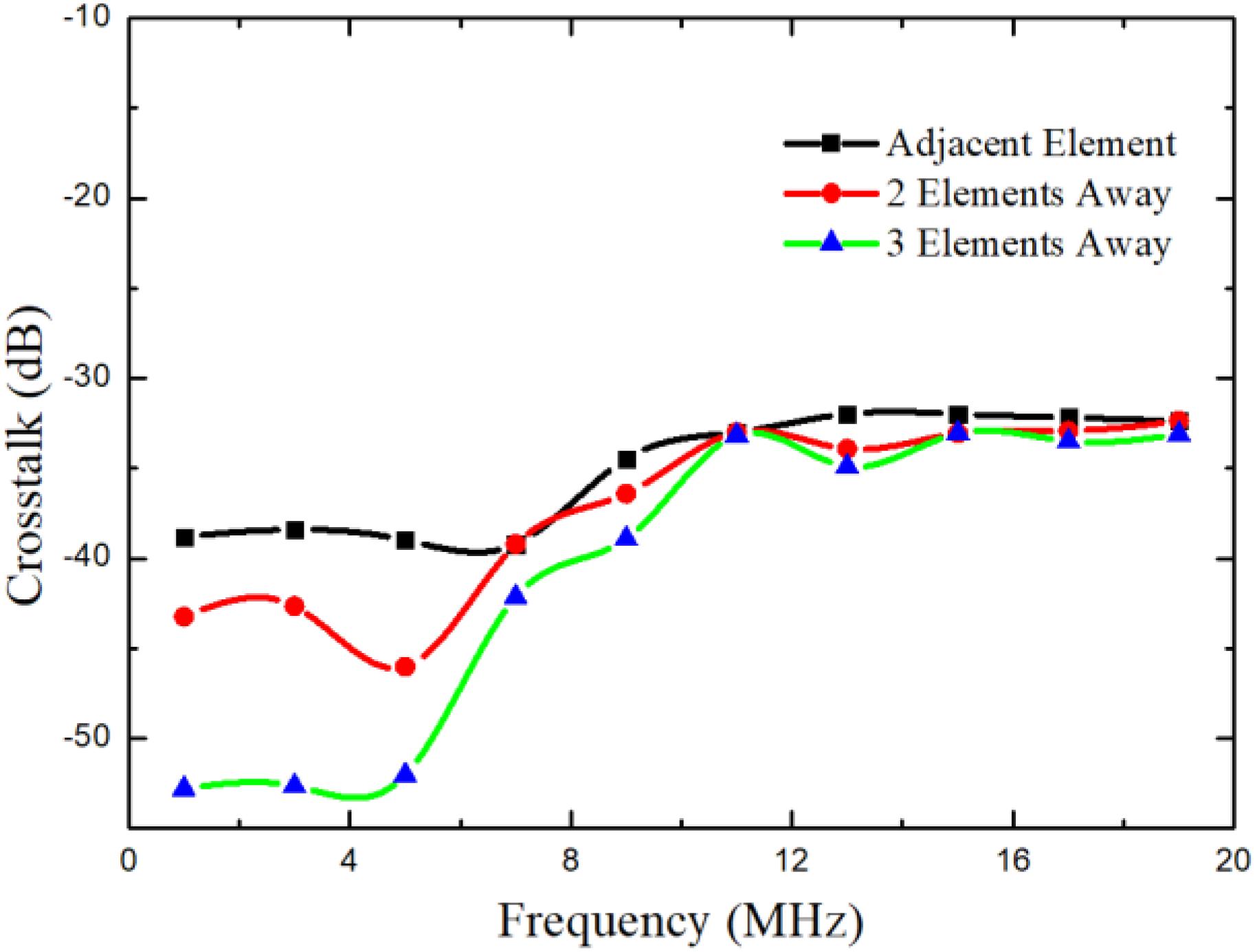
Figure 10. Measured cross talk for the array.
The cross talk decreased fast in the lower frequency and almost no change in the higher frequency. This phenomenon may be caused by the parasitic capacitance formed by the array elements. The parasitic capacitance is a high-pass filter for the cross talk.
The long wire electrode binding and flexible circuit affected the electrical impedance characteristics of the transducer, resulting in the lower value of peak-to-peak voltage in the measurement. The electrical impedance curve can be used to analyze the impact of wire (Jian et al., 2018) and the FPC board.
The one-way azimuthal directivity response of the phased-array transducer was measured by exciting the one-array element (element 23) using the pulser/receiver DPR500. The element was rotated around an axis with a precise rotating device (QRP02, Thorlabs, Newton, NJ, United States) in a step of 3°, along its center and length, and the amplitudes of the response were acquired at discrete angular positions by a hydrophone (NH0200, Precision Acoustic, Dorset, United Kingdom) with 0.2 mm diameter. For the transducer, the measurement of − 6 dB directivity was ± 30°, as shown in Figure 11, which can serve satisfactorily in the performance of phased-array beam. Similar results were reported with directivity of approximately ±25° for a 2–2 composite phased array (Bezanson et al., 2014; Cabrera-Munoz et al., 2019).
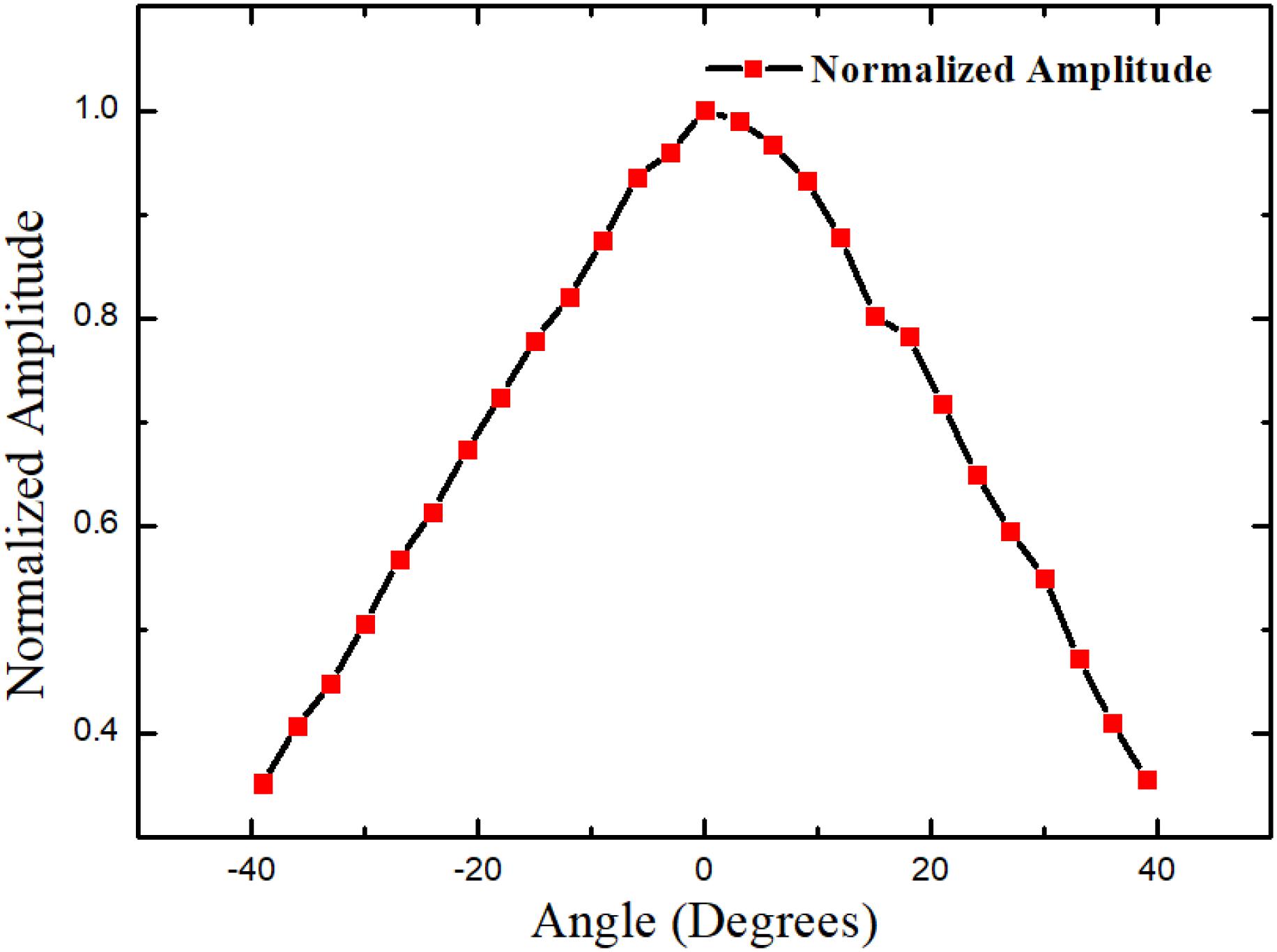
Figure 11. Measured one-way directivity of element 23.
The authors utilized Verasonics Vantage 128 System to determine the imaging capability of the phased array. The probe is driven by a single-cycle sinusoidal tone-burst signal with an amplitude of 50 V, and the DELAY-AND-SUM (DAS) beamforming method is used in the system, which is the most basic digital beamformer for medical ultrasound imaging (Friis and Feldman, 1937; Mailloux, 1982), and the phantom images are presented in a 50-dB dynamic range. The catheter can operate at frequencies of 6.5–11.5 MHz.
To evaluate the performance, the custom-made wire phantoms were used to carry out the image tests. The lateral resolution and axial resolution were detected by wire phantom (Foster et al., 2002) at the central frequency of 9 MHz of the catheter. We can calculate the theoretical spatial resolution using the following equations based on pulse-echo response:
where PL is the − 6 dB spatial pulse length of the received echo and the measured value is 217 μm, and the theoretical axial spatial resolution RA is 108.5 μm.
where F# is the F number of the transducer (1.9) and λ is the sound wavelength in the medium (167 μm in water); therefore, the theoretical lateral spatial resolution RL is 317 μm.
The 50-μm diameter wires phantom was immersed in a tank and imaged with gray scale in a 50-dB dynamic range as shown in Figure 12. The spread functions of A wire image axial and lateral line were plotted and are shown in Figure 13.
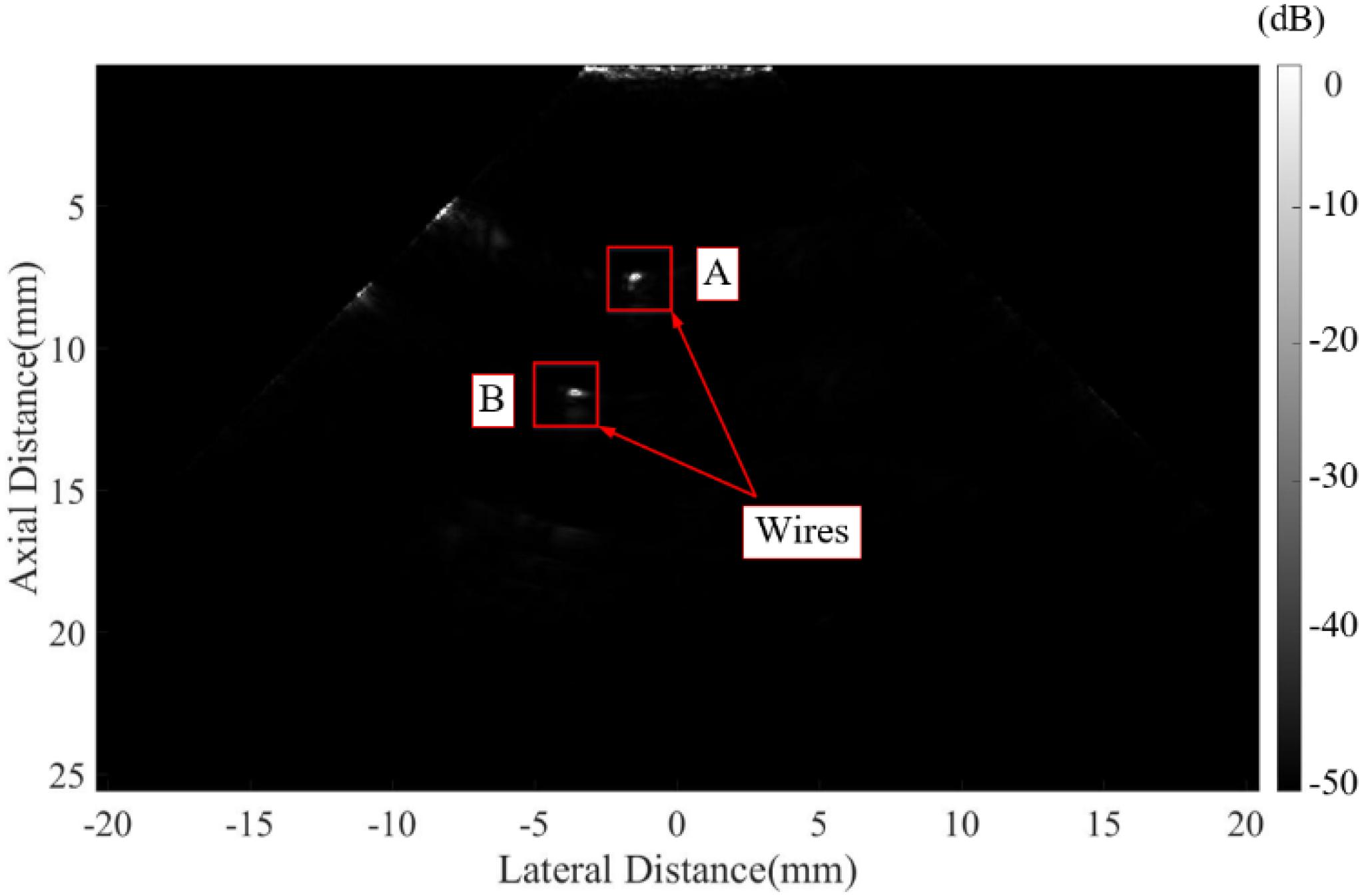
Figure 12. Image of wire phantom.
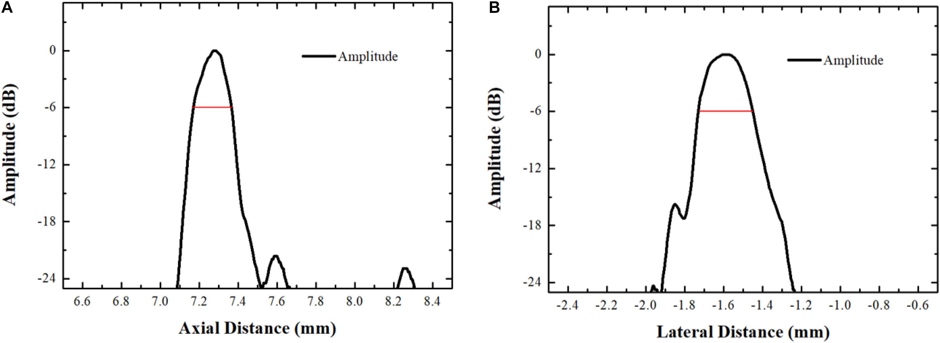
Figure 13. (A) Axial and (B) lateral line spread functions.
The measured axial and lateral resolutions at −6 dB are 188 and 321 μm, respectively, and the lateral value is close to its theoretical value, but the axial value has a large deviation because the wire is difficult to be placed in the theoretical focus position.
Figure 14 shows an ultrasonic image of a phantom with 10 evenly 10-mm-spaced tungsten wires immersed in a tank with deionized water, and it is clear to find that the wire at a penetration depth of 100 mm can be easily observed with reasonable image quality. The SNR of the wires image was analyzed according to the RF data acquired by the Vantage system, which is higher than 30 dB. The spatial resolutions and penetration performance are satisfactory and can meet the requirements of ICE imaging.
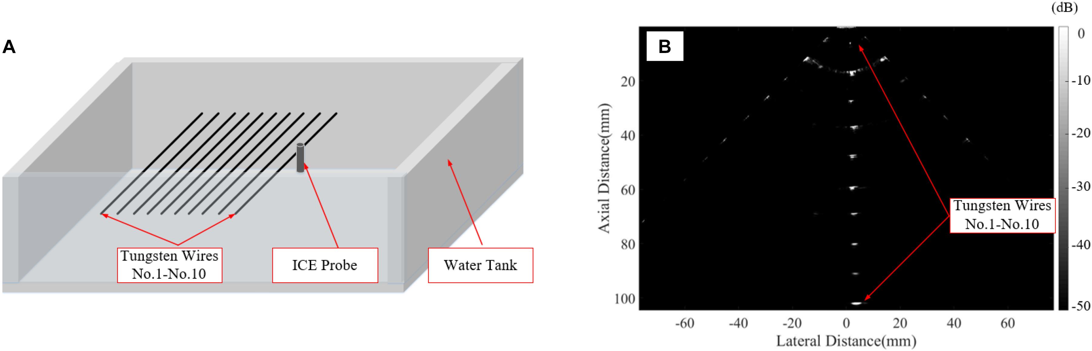
Figure 14. (A) The image of wires phantom and (B) the wire phantom images of penetration depth.
A commercial phantom (KS107BG, Institute of Acoustics, Beijing, China), as shown in Figure 15A, was also employed in the experiment. It can be observed from Figure 15B that the wires in the distal area have a superior resolution (<0.5 mm), which shows that the transducer has an excellent beam steering performance.
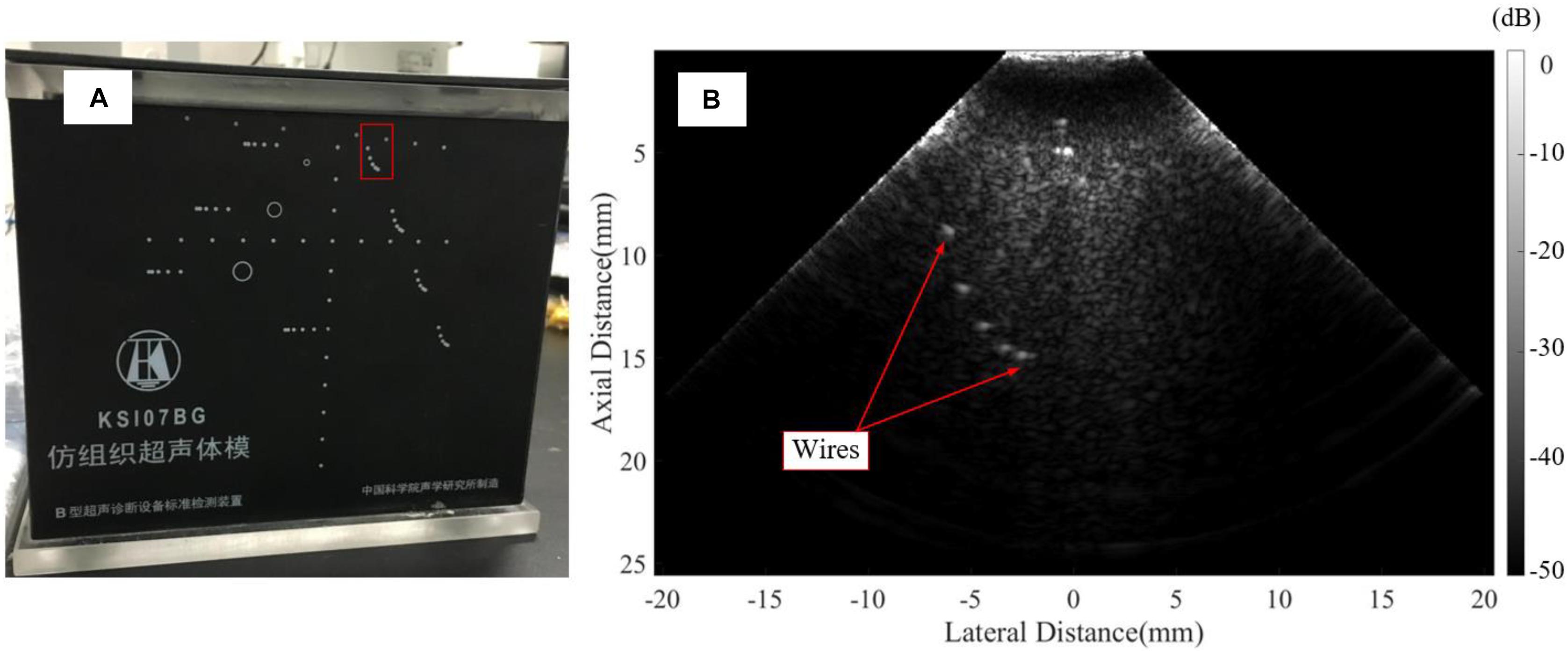
Figure 15. (A) A commercial phantom (KS107BG, Institute of Acoustics, Beijing, China), and (B) The commercial wire phantom image.
This study described the development of a 1–3 piezocomposite-based phased-array transducer fit inside of a four-direction steerable ICE catheter. The dice-and-fill technique was used to produce the 1–3 piezocomposite material, and an encase structure and half-cut methods were developed to reduce the complexity of the fabrication process. Utilizing fabricated 1–3 piezocomposite, a transducer with a size of 2 mm × 7.4 mm with a central frequency of 9 MHz and −6 dB BW of 55% was prototyped. According to the echo and wire phantom experiments, the basic performance of the phased array was excellent. The experimental results suggest that a novel fabricated process of 1–3 composite phased array is competent for the single-use disposable ICE catheter in the future.
The original contributions presented in the study are included in the article/supplementary material, further inquiries can be directed to the corresponding authors.
ZH, ZL, XJ, and YCu conceived and designed the research work. NW, ZL, and YCh analyzed the data. ZH and XZ performed the experiments. All authors contributed to the article and approved the submitted version.
This work was supported in part by the National Key Research and Development Program of China (Grant Nos. 2019YFC0120500 and 2018YFC0116201), the Funds of Youth Innovation Promotion Association, Chinese Academy of Sciences (Grant Nos. Y201961, 20A122062ZY, and YJKYYQ20180031), and Funds of Suzhou Science and Technology Project (SS202062).
The authors declare that the research was conducted in the absence of any commercial or financial relationships that could be construed as a potential conflict of interest.
Alkhouli, M., Hijazi, Z. M., Holmes, D. R. Jr., Rihal, C. S., and Wiegers, S. E. (2018). Intracardiac echocardiography in structural heart disease interventions. JACC Cardiovasc. Interv. 11, 2133–2147. doi: 10.1016/j.jcin.2018.06.056
Bartel, T., Müller, S., Biviano, A., and Hahn, R. T. (2014). Why is intracardiac echocardiography helpful? Benefits, costs, and how to learn. Eur. Heart J. 35, 69–76. doi: 10.1093/eurheartj/eht411
Basij, M., Yan, Y., Alshahrani, S. S., Helmi, H., Burton, T. K., Burmeister, J. W., et al. (2019). Miniaturized phased-array ultrasound and photoacoustic endoscopic imaging system. Photoacoustics 15:100139. doi: 10.1016/j.pacs.2019.100139
Bezanson, A., Adamson, R., and Brown, J. A. (2014). Fabrication and performance of a miniaturized 64-element high-frequency endoscopic phased array. IEEE Trans. Ultrason. Ferroelectr. Freq. Control 61, 33–43. doi: 10.1109/TUFFC.2014.6689774
Bezanson, A., Garland, P., and Brown, J. (2020). “A comparison study between high-frequency kerfless and fully-kerfed ultrasonic phased arrays,” in Proceedings of the 2020 IEEE International Ultrasonics Symposium (IUS) (Las Vegas, NV: IEEE), 1–5.
Boonruang, A., Thongchai, T., Button, T., and Cochran, S. (2019). “Microfabrication of 1-3 composites with photolithographically defined electrode patterns for kerfless microultrasound arrays,” in Proceedings of the 2019 IEEE International Ultrasonics Symposium (IUS) (Glasgow: IEEE), 1746–1749.
Brown, J. A., Foster, F. S., Needles, A., Cherin, E., and Lockwood, G. R. (2007). Fabrication and performance of a 40-MHz linear array based on a 1-3 composite with geometric elevation focusing. IEEE Trans. Ultrason. Ferroelectr. Freq. Control Vol. 54, 1888–1894. doi: 10.1109/TUFFC.2007.473
Cabrera-Munoz, N. E., Eliahoo, P., Wodnicki, R., Jung, H., Chiu, C. T., and Williams, J. A., et al. (2019). Fabrication and characterization of a miniaturized 15-MHz side-looking phased-array transducer catheter. IEEE Trans. Ultrason. Ferroelectr. Freq. Control 66, 1079–1092. doi: 10.1109/tuffc.2019.2906134
Cannata, J. M., Williams, J. A., Chang-Hong, H., and Shung, K. K. (2008). “Development of high frequency linear arrays using interdigital bonded composites,” in Proceedings of the2008 IEEE Ultrasonics Symposium (Beijing: IEEE), 686–689.
Cannata, J. M., Williams, J. A., Qifa, Z., Ritter, T. A., and Shung, K. K. (2006). Development of a 35-MHz piezo-composite ultrasound array for medical imaging. IEEE Trans. Ultrason. Ferroelectr. Freq. Control Vol. 53, 224–236. doi: 10.1109/TUFFC.2006.1588408
Chen, R., Cabrera-Munoz, N. E., Lam, K. H., Hsu, H. S., Zheng, F., Zhou, Q., et al. (2014). PMN-PT single-crystal high-frequency kerfless phased array. IEEE Trans. Ultrason. Ferroelectr. Freq. Control Vol. 61, 1033–1041. doi: 10.1109/tuffc.2014.2999
Chen, R., Wu, J., Ho Lam, K., Yao, L., Zhou, Q., Tian, J., et al. (2012). Thermal-independent properties of PIN-PMN-PT single-crystal linear-array ultrasonic transducers. IEEE Trans. Ultrason. Ferroelectr. Freq. Control Vol. 59, 2777–2784. doi: 10.1109/TUFFC.2012.2519
Chiu, C. T., Williams, J. A., Kang, B. J., Abraham, T., Shung, K. K., and Kim, H. H. (2014). “Fabrication and characterization of a 20 MHz microlinear phased array transducer for intervention guidance,” in Proceedings of the 2014 IEEE International Ultrasonics Symposium (Chicago, IL: IEEE), 2121–2124.
Cochran, S., MacLennan, D., Button, T. W., Hughes, H., Ponting, M., and Sweet, J. (2006). “P3Q-1 ultra precision grinding in the fabrication of high frequency piezocomposite ultrasonic transducers,” in Proceedings of the 2006 IEEE Ultrasonics Symposium (Vancouver, BC: IEEE), 2353–2356.
CTS (2021). Piezoelectric Polycrystalline (PZT) Components and Wafers. Available online at: www.ctscorp.com/wp-content/uploads/CTS-Corporation-Piezoelectric-Polycrystalline-PZT-Components-and-Wafers.pdf).
Dias, C. J., and Das-Gupta, D. K. (1994). “Electroactive polymer-ceramic composites,” in Proceedings of the 1994 4th International Conference on Properties and Applications of Dielectric Materials (ICPADM)), Vol. 1, (Brisbane, QLD: IEEE), 175–178.
Enriquez, A., Saenz, L. C., Rosso, R., Silvestry, F. E., Callans, D., Marchlinski, F. E., et al. (2018). Use of intracardiac echocardiography in interventional cardiology: working with the anatomy rather than fighting it. Circulation 137, 2278–2294. doi: 10.1161/circulationaha.117.031343
Foster, F. S., Zhang, M. Y., Zhou, Y. Q., Liu, G., Mehi, J., Cherin, E., et al. (2002). A new ultrasound instrument for in vivo microimaging of mice. Ultrasound Med. Biol. 28, 1165–1172. doi: 10.1016/s0301-5629(02)00567-7
Friis, H. T., and Feldman, C. B. (1937). A multiple unit steerable antenna for short-wave reception. Bell Syst. Tech. J. 16, 337–419. doi: 10.1002/j.1538-7305.1937.tb00425.x
Hijazi, Z. M., Shivkumar, K., and Sahn, D. J. (2009). Intracardiac echocardiography during interventional and electrophysiological cardiac catheterization. Circulation 119, 587–596. doi: 10.1161/circulationaha.107.753046
Jian, X., Li, Z., Han, Z., Xu, J., Liu, P., Liu, Y., et al. (2018). the study of cable effect on high-frequency ultrasound transducer performance. IEEE Sens. J. 18, 5265–5271. doi: 10.1109/JSEN.2018.2838142
Kim, H. H., Hu, C., Park, J., Kang, B. J., Williams, J. A., Cannata, J. M., et al. (2010). “Characterization and evaluation of high frequency convex array transducers,” in 2010 IEEE International Ultrasonics Symposium (San Diego, CA: IEEE), 650–653.
Kim, K.-B., Hsu, D. K., Ahn, B., Kim, Y.-G., and Barnard, D. J. (2010). Fabrication and comparison of PMN-PT single crystal, PZT and PZT-based 1-3 composite ultrasonic transducers for NDE applications. Ultrasonics 50, 790–797. doi: 10.1016/j.ultras.2010.04.001
Lukacs, M., Yin, J., Pang, G., Garcia, R. C., Cherin, E., Williams, R., et al. (2006). Performance and characterization of new micromachined high-frequency linear arrays. IEEE Trans. Ultrason. Ferroelectr. Freq. Control 53, 1719–1729. doi: 10.1109/TUFFC.2006.105
Luo, L., Zhao, X., and Luo, H. (2010). “Chapter 7 - single crystal PZN-PT, PMN-PT, PSN-PT, and PIN-PT-based piezoelectric materials,” in Advanced Piezoelectric Materials (Second Edition), ed. K. Uchino (Sawston: Woodhead Publishing), 271–318. doi: 10.1016/b978-0-08-102135-4.00007-2
Mailloux, R. J. (1982). Phased array theory and technology. Proc. IEEE 70, 246–291. doi: 10.1109/PROC.1982.12285
Smith, W. A., and Auld, B. A. (1991). Modeling 1-3 composite piezoelectrics: thickness-mode oscillations. IEEE Trans. Ultrason. Ferroelectr. Freq. Control 38, 40–47. doi: 10.1109/58.67833
Sung Min, R., Hyung Ham, K., Ho, J., Seduk, K., and Sang-Goo, L. (2003). “A 128 channel 7.5 MHz linear array ultrasonic probe using PMN-PT single crystal,” in Proceedings of the IEEE Symposium on Ultrasonics, 2003, Vol. 781, (Honolulu, HI: IEEE), 782–785.
Vitulano, N., Pazzano, V., Pelargonio, G., and Narducci, M. L. (2015). Technology update: intracardiac echocardiography - a review of the literature. Med Devices 8, 231–239. doi: 10.2147/mder.S49567
Wong, C. M., Chen, Y., Luo, H., Dai, J., Lam, K. H., and Chan, H. L. (2017). Development of a 20-MHz wide-bandwidth PMN-PT single crystal phased-array ultrasound transducer. Ultrasonics 73, 181–186. doi: 10.1016/j.ultras.2016.09.012
Yang, H. C., Cannata, J., Williams, J., and Shung, K. K. (2012). Crosstalk reduction for high-frequency linear-array ultrasound transducers using 1-3 piezocomposites with pseudo-random pillars. IEEE Trans. Ultrason. Ferroelectr. Freq. Control 59, 2312–2321. doi: 10.1109/tuffc.2012.2456
Zhang, J. Y., Xu, W. J., Carlier, J., Ji, X. M., Nongaillard, B., Queste, S., et al. (2011). “Fabrication and characterization of half-kerfed LiNbO3-based high-frequency (>100MHz) ultrasonic array transducers,” in Proceedings of the 2011 IEEE International Ultrasonics Symposium) (Orlando, FL: IEEE), 1727–1730.
Zhang, Q., Li, Y., Liu, J., Huang, J., Tan, Q., Wang, C., et al. (2020). A PMN-PT composite-based circular array for endoscopic ultrasonic imaging. IEEE Trans. Ultrason. Ferroelectr. Freq. Control 67, 2354–2362. doi: 10.1109/TUFFC.2020.3005029
Zhangjian, L., Zhile, H., Xiaohua, J., Weiwei, S., Yang, J., and Yaoyao, C. (2020). Pulse-echo acoustic properties evaluation method using high frequency transducer. Meas. Sci. Technol. 31:125011. doi: 10.1088/1361-6501/aba0d8
Zhou, D., Cheung, K. F., Chen, Y., Lau, S. T., Zhou, Q., Shung, K. K., et al. (2011). Fabrication and performance of endoscopic ultrasound radial arrays based on PMN-PT single crystal/epoxy 1-3 composite. IEEE Trans. Ultrason. Ferroelectr. Freq. Control 58, 477–484. doi: 10.1109/TUFFC.2011.1825
Keywords: 1–3 composite, phased array, intracardiac echocardiography, high frequency, miniature transducer
Citation: Han Z, Wang N, Li Z, Zhu X, Chen Y, Jian X and Cui Y (2021) Phased-Array Transducer for Intracardiac Echocardiography Based on 1–3 Piezocomposite. Front. Mater. 8:663926. doi: 10.3389/fmats.2021.663926
Received: 04 February 2021; Accepted: 01 April 2021;
Published: 22 April 2021.
Edited by:
Zeyu Chen, Central South University, ChinaReviewed by:
Benpeng Zhu, Huazhong University of Science and Technology, ChinaCopyright © 2021 Han, Wang, Li, Zhu, Chen, Jian and Cui. This is an open-access article distributed under the terms of the Creative Commons Attribution License (CC BY). The use, distribution or reproduction in other forums is permitted, provided the original author(s) and the copyright owner(s) are credited and that the original publication in this journal is cited, in accordance with accepted academic practice. No use, distribution or reproduction is permitted which does not comply with these terms.
*Correspondence: Yaoyao Cui, Y3VpeXlAc2liZXQuYWMuY24=; Xiaohua Jian, amlhbnhoQHNpYmV0LmFjLmNu
Disclaimer: All claims expressed in this article are solely those of the authors and do not necessarily represent those of their affiliated organizations, or those of the publisher, the editors and the reviewers. Any product that may be evaluated in this article or claim that may be made by its manufacturer is not guaranteed or endorsed by the publisher.
Research integrity at Frontiers
Learn more about the work of our research integrity team to safeguard the quality of each article we publish.