 Guanghao Chu
 Bin Zhou1,2
 Guangbin Shao
 Longqiu Li
94% of researchers rate our articles as excellent or good
Learn more about the work of our research integrity team to safeguard the quality of each article we publish.
Find out more
ORIGINAL RESEARCH article
Front. Mater. , 18 May 2021
Sec. Smart Materials
Volume 8 - 2021 | https://doi.org/10.3389/fmats.2021.661593
This article is part of the Research Topic Four-dimensional (4D) Printing View all 11 articles
Four-dimensional (4D) printed structures are usually designed with reduced stiffness to enlarge the deformation response and weaken the loading capacity in actuated states. These actuators are suitable for non-persistent loads, such as is involved in grabbing action by a 4D printed claw. However, reduced stiffness cannot support continuous external loads during actuation. To tackle the trade-off between deformation and loading capacity, we propose herein a design using alternate actuation to attain competent loading capacity in different deformed states. In this alternate design, each unit consists of two actuated components featuring the same deformation but reciprocal stiffness, which provides the overall structural stiffness required to attain competent loading capacity during the entire deformation process. The two components are programmed to have the deformation behavior and are stimulated by thermal-expansion mismatch between polylactic acid (PLA) and carbon-fiber-reinforced PLA. An actuator featuring alternate components was designed and 4D printed to contrast its loading capacity with that of the traditional design. Experiments demonstrate a significantly improved loading capacity during actuation. This work thus provides a designing strategy for 4D printed actuators to retain competent loading capacity during the entire deformation process, which may open promising routes for applications with continuous external loads, such as 4D printed robotic arms, walking robots, and deformable wheels.
Four-dimensional (4D) printing is a creative manufacturing technology that combines three-dimensional (3D) printing technology with smart materials or structures, where the shape, property, or functionality for 4D structures can be programmed and controlled in space and time (Momeni et al., 2017; Kuang et al., 2018). The structures can be manufactured by using 3D printing technology such as fused filament fabrication (Cheng et al., 2020), direct ink writing (Yuan et al., 2017), stereolithography (Ge et al., 2016), or polyjet (Ding et al., 2018), all of which can change their morph or function by optical stimulation (Liu et al., 2017), electrical stimulation (Bar-Cohen et al., 2017; Zhao et al., 2019), variations in humidity (Gladman et al., 2016; Lee et al., 2020), magnetic stimulation (Kim et al., 2018), thermal variations (Ge et al., 2014; Ding et al., 2017), etc.
The internal properties of materials can change before, during, and after the environmental stimulation. The deformation process of the structure may be destroyed when the external load exceeds the stiffness of the component (Shi et al., 2020). Therefore, one of the most important issues in 4D printing is the loading capacity and deformation force in different actuated states. Most research focuses on characterizing the response of 4D printed structures made of the proposed materials and elucidating the associated principles. These 4D printing studies fall into three categories: The first is to use shape memory polymer materials with desirable mechanical properties. For example, Akbari et al. (2018) enhanced the recovery force by combining active hinges with flexible elastic hinges that store elastic strain energy during programming. A 50 g weight was placed on an actuator to demonstrate the recovered shapes of the deployable structure under load. Xin et al. (2020) showed that the recovery force of the active sandwich structures can exceed 300 mN. The structure in this study is appealing in terms of its high loading capacity during deformation, but only one-way deformation has been achieved under an external load. The second category of 4D printed structures can deform reversibly but cannot guarantee the deformation process under continuous loads. The arched strip presented by Mao et al. (2016) had a loading capacity of 250 mN in the cooling state, which endowed it with single-state stiffness through a multi-material design. Yuan et al. (2021) reported a 500 g loading capacity at various temperatures for a 3D structure constructed by a multi-material, direct 4D printing. In addition, the origami structure printed by Zhang et al. (2020) can withstand 200 g after deformation. The goal of both studies was to investigate the stiffness of 4D printed structures after drying. Yang et al. (2017) measured the thermal deformation of composite materials when the temperature is below the glass-transition temperature and found that the maximal deformation and deformation force for carbon fiber-PLA specimens are 7 mm and 100 mN, respectively, with the structure deformed in a single direction. Finally, the third category of 4D printed structures uses thin-film materials such as liquid crystal elastomer (LCE). Kotikian et al. (2018) and López-Valdeolivas et al. (2018) demonstrated the contraction of LCE with loads of 5 and 20 g, respectively, in the tensile direction. However, the LCE structure is not sufficiently stiff in the other directions.
As mentioned above, existing studies focus on the structural stiffness of a single actuated state or on the deformation force in a one-way process of 4D printing but ignores the loading capacity during the entire deformation process. The key problem in changing shape under continuous loads is the relationship between actuated internal forces and structural stiffness. The internal forces caused by environmental stimulation can change the shape of 4D printed structures by overcoming structural stiffness. However, this internal force is generally small, so that 4D printed structures are not expected to be stiff during deformation. This explains why current 4D printed structures with significant deformation usually have low stiffness during actuation: it is caused by a decrease in the modulus of the smart material due to an externally induced deformation (Shiblee et al., 2018; Chen et al., 2020) or by a reduced stiffness of the deformation area due to a hinge structure (Zhu et al., 2018). The end result is that the structure is unable to carry loads at certain points in the deformation process. To improve loading capacity during the entire deformation process and maintain deformation behavior, there are two ways to solve this issue. On the one hand, we can propose a method to improve internal forces and, on the other hand, we can propose a design that avoids the conflicts between deformation behavior and structural stiffness.
We propose a design strategy that involves connecting two actuated components in parallel so that the 4D printed structure offers sufficient loading capacity during the reversible deformation process. By alternately heating the parallel components, the endpoint of each component has the same deformation path but the opposite stiffness. The structure can thus carry continuous loads during two-way deformations but with high stiffness in each state. The actuator component is driven by a current joule heating for a 4D printed carbon fiber reinforced composite structure. We investigate this design by using a multilayer composite structure that changes shape in response to thermal stimuli (Momeni et al., 2017). We develop a design method and printing process for this thermal mismatch principle and extend the design method to arbitrary curved structures. Next, we compare the alternate-actuated structure with traditional designs to demonstrate the advantages of the proposed design in terms of deformation capacity under continuous loads. We also design a walking robot to further demonstrate the multi-directional loading capability of the alternate actuation design. This study thus proposes a method to retain the mechanical properties of 4D printed structures subjected to various deformed states and provides a useful strategy for 4D printed structures to function under continuous loads.
We designed a 4D printed composite structure for two layers, one layer composed of thermoplastic resin and the other layer composed of continuous fiber composite material, as shown in Figure 1A. During heating, the 4D printed structure bends and then, upon cooling, recovers its initial state. We fabricated a composite structure by using a six-axis parallel manipulator (Zhang et al., 2019a) with coaxial nozzles (Qiao et al., 2019), based on the polylactic acid (PLA, JG Maker Corp. in China) as matrix material and continuous carbon fiber (TORAY Corp. in Japan) as reinforcement. Current-driven joule heating was provided by carbon fiber to actuate the 4D printed structure (Wang et al., 2018a). Thus, we could drive different actuated units in multiple areas of the same structure at different times to produce a variety of deformations.
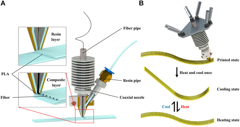
FIGURE 1. 4D printed structure consisting of a composite layer and a resin layer. (A) Two-layer structure model and printing schematic. (B) Three different states of 4D printed structure showing their transformations.
During printing, the structure was observed in three different states: the printed state, cooling state, and heating state (see Figure 1B). The printed state is the state of the structure after being printed. Due to the rapid cooling, the printed structure is undeformed and has no inherent thermal stress. Any thermal stress is attributed to the difference in thermal expansion coefficients between the continuous fiber composite material and the thermoplastic resin. Later, an additional heat cycle is applied to release the residual stress inside the printed structure (Wang et al., 2018b). When heating, the residual stress is released to offset any deformation causing by thermal expansion mismatch. As the material cools, the structure enters the cooling state by bending toward the side of resin layer, which does not affect without the influence for the residual stress. Finally, a potential difference is applied across the carbon fiber in the composite layer to drive a current and transform the cooling state into the heating state. Once the potential difference is removed, the material cools and re-enters the cooling state. The heating state is like the printed state, and the change in bending angle between the cooling state and heating state depends on the design parameters of the structure and on the actuation.
The structural stiffness decreases as the temperature increases because of the temperature dependence on the mechanical properties of the matrix materials (Zhang et al., 2019b). At excessively high actuating temperature, 4D printed structures cannot provide a high loading capacity during the actuated state. With low actuating temperature, the structural deformation becomes too small to provide any function as an actuator. Therefore, traditional designs have trouble simultaneously producing the desired mechanical properties and deformation properties of 4D printed structures.
Figure 2A introduces an alternate design for actuation. The structure for deformation is split into at least two groups of parallel beam structures, namely, beams A and B. The two beam groups have the same endpoints in the opposite actuated status. In other words, the endpoints of beam A at low temperature are the same as those of beam B at high temperature, and vice versa. We alternately heated the fiber drive circuit in beams A and B to ensure that the low-temperature beam always provides sufficient stiffness to support the load.
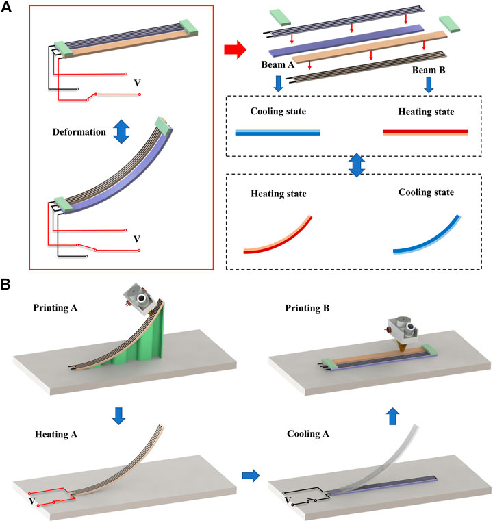
FIGURE 2. Design of alternate-actuated structure for (A) two groups of beam structures and (B) printing process.
We designed the printing paths for beams A and B in the heating state. Next, we predicted the cooling state of beam A and designed the printing paths for the structure that connects the cool state of beam A to the hot state of beam B. Herein, we equate the printed state with the heating state of beam B to simplify the complexity of design and printing.
We used a multi-axis fused filament fabrication printing device to create the designed structure and connected the deformable components by using the fabrication process shown in Figure 2B. The main steps are as follows:
1) Appropriate support is designed and printed with pure resin, following which we print the heating state of beam A and then remove the support after beam A cools.
2) We interrupt the printing process and energize the internal fibers. When heating, any residual stress in beam A is released.
3) We disconnect the heating power and wait for beam A to cool to room temperature. As it cools, the deformed beam A enters the cool state.
4) We print the heating state of beam B and connect beam B to the cool state of beam A to finish the fabrication of the alternate-actuated structure.
Currently, the two parallel components deform in the same way under opposite actuation conditions. Beams A and B both provide benefits for bending in the same direction to retain the deformation performance while improving the structural loading capacity.
The design goal of the alternate-actuated structures is to ensure that the endpoint of beam A in the cool state is the same as that of beam B in the heating state and vice versa. And the end trajectories of the beam A and beam B should be similar when shape changing, to reduce interference as the structure deforms. Therefore, the different states of the 4D printed structure need to be defined in advance.
We control the bending direction by adjusting the fiber orientation and present a mathematical model to predict the deformation amplitude. The bending angle
where
The three parameters a, b, c depend on the sectional structure, yielding
where
It can be obtained from the formula that the material properties, actuation parameters and structural design parameters affect the deformation behavior of a single actuator. The bending performance correlates positively to the actuation temperature and the length of the strip, whereas the bending angle is independent of strip width. The influence from the sectional structure is more complicated. It can be found that the thickness distribution of the fiber layer and the resin layer, the volume fraction of the fiber bundle, and the arrangement density of the fibers all affect the cross-sectional morphology. This part is greatly affected by the printing process, which is not discussed in this article.
To predict the deformation, we apply a dynamic thermomechanical analysis (DMA) to the polymer matrix material to determine the glass-transition temperature and the storage modulus as a function of temperature. For this, we use the DMA tester model NETZSCH DMA 242 from TA Instruments (New Castle, DE, United States). The temperature of the samples cut to 20 mm × 5 mm × 1 mm was increased from 20 to 95°C at a rate of 5°C per min. Figure 3A shows the temperature dependence of the storage modulus and
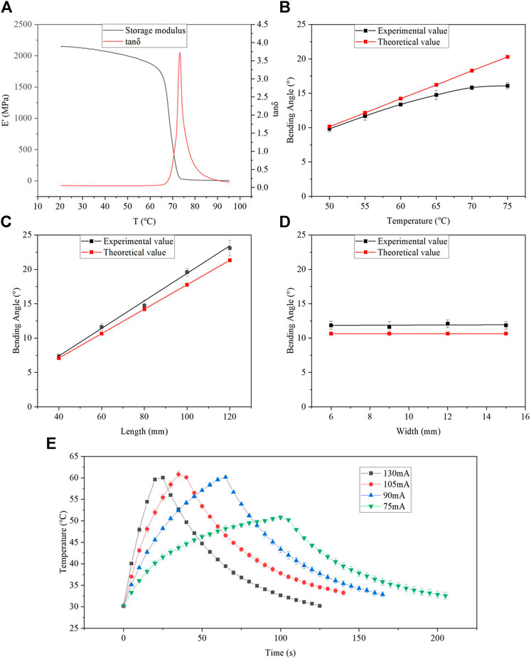
FIGURE 3. (A) Results of DMA test of matrix material. Characterization of bending angle as a function of (B) actuation temperature, (C) design length, (D) design width. (E) Temperature as a function of time for various actuation currents.
We demonstrate the accuracy with which the theoretical model predicts the experimental results. The test samples are designed as long strip structures with the same cross section as in the theoretical model. The fibers in the composite layer were arranged lengthwise in the structure. The thickness and the distance between adjacent fibers were fixed at 1.5 mm, and the volume fraction of fibers in the composite material is calculated to be 5%. We move the nozzle at speed of 0.005 m/s to complete the printing of PLA matrix and fiber-reinforced composite material at 210°C. The single printing path has a line width of 1.5 mm and a layer height of 0.5 mm. The fiber material printed into the resin matrix is 1 K Toray carbon fiber. During printing, we embedded thermal elements to better control the temperature and the accuracy of the 4D printing through a temperature-control feedback circuit. Figure 3B shows the bending angle as a function of temperature. The theoretical prediction is obtained from Eqs 1–4 combined with the DMA test parameters and the actual structure parameters. The experimental results were obtained by using Image J to measure the bending angle of the sample. We used a structure size of 60 mm × 6 mm × 1.5 mm. It is apparent from this result that the bending angle has a significant positive correlation with the actuation temperature. When the temperature is less than 70°C, the margin of error between the experimental and theoretical results remains within 10%. At higher temperatures, the experimental results depart significantly from theory, which is attributed to the fact that gravity affects the experiment when the sample softens above the glass-transition temperature. Figures 3C,D show the relationship between bending angle and structural design parameters. The experimental results obtained at 60°C confirm the positive correlation between the bending angle and the length of the strip. Then shown in Figure 3D, the bending angle does not change with the width of the strip. All experimental data fall within 10% of the theoretical results.
Figure 3E shows the temperature during actuation by different currents. The sample size is 60 mm × 9 mm × 1.5 mm, and the ambient temperature is 20°C. During heating, the heating rate gradually decreases with increasing temperature so that the sample may reach thermal equilibrium with the help of external heat dissipation. During natural cooling, the cooling rate of the sample gradually reduces as the temperature decreases until the temperature reaches the ambient temperature. The variations in temperature during heating and cooling both go from fast to slow, which is advantageous to maintain consistent deformation for the parallel components of composite structure. A driving current of 80 mA proved best to ensure synchronous deformation. Both the heating and cooling phases were designed as 1 min with temperature variation between 35 and 60°C.
To confirm that the design strategy is suitable for complex structural design, arbitrary curved components now replace simple strips or beams in the alternate-actuated structure. The key is to ensure that the deformation endpoints follow consistent paths for both components.
This study used geometric analysis to summarize the general design. The beam structure with a single fiber orientation is divided into n segments of unequal arcs. As presented in Figure 4,
Let
In the same way, the coordinates of the end of the structure after deformation can be expressed using Eqs 5–7. The new
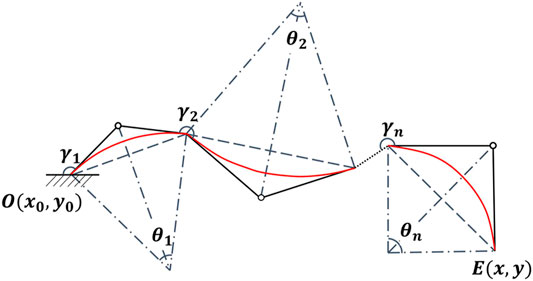
FIGURE 4. Geometric decomposition of 4D deformed beam into n arc segments.
We consider the sample shown in Figure 5A to demonstrate the proposed design method. The sample consists of two different parallel components, with diverse shape in opposite actuated state. We split each component into the length of the two curves where
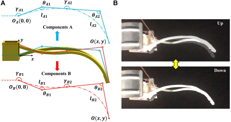
FIGURE 5. Results of complex sample consisting of two parallel components. (A) Geometric analysis of parallel components. (B) Actual deformation of sample.
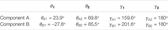
TABLE 1. Design parameters of each parallel components.
The deformed sample is shown in Figure 5B. And the print process, cross-sectional images and deformation video are shown in Supplementary Figures S2, S3; Supplementary Video S1. The deformation along the y axis was measured by using ImageJ and is about 5.1 mm, which is 92% compared to the design value. The main reason for the reduced deformation is the uneven thickness caused by insufficient printing accuracy. In addition, the rigid connection at the end of the structure also has negligible effect on the deformation.
To compare the loading capacity of the alternate actuation design with that of traditional designs, we tested reversible variations in shape under a hanging load. When actuating with a 90 mA current, the structural deformation and recovery both last 60 s. Figure 6A shows how the traditional sample swings up under a 10 g load. The sample was designed with parallel beams which the fiber arrangements for two parallel components are on the same side. Figure 6C shows the results for the bending angle first heating and then cooling under different loads, both of the heating phase and cooling phase are 60 s. The black, red and blue curves correspond to bending performance under 0, 10, and 100 g loads. The results show that the bending curve early recover at 40 s instead of 60 s. It means that the load capacity of the structure at 40 s is no longer able to carry 10 g load because the stiffness decreases due to rising temperature. The curve under a load of 100 g also shows the destruction of deformation behavior when the structure is heated in 0∼60 s. Additionally, the structure has additional reverse deformation when they recover under the 10 and 100 g load. In the heating phase, the structure is irreversibly deformed under the influence of load, so the deformation at the end of heating is much smaller than the no-load deformation. But in the cooling phase, the structure in high temperature state is subjected to a small force in the direction of recover because of the irreversibly deformed. Therefore, recovery of the structure is less affected by the load, the recovery angle is similar as the no-load bending angle. The difference in deformation between heating and cooling caused this additional reverse deformation. In summary, the traditional deformation structure cannot be used under more than 10 g load because of the influence of early recovery during heating and additional reverse deformation during cooling.
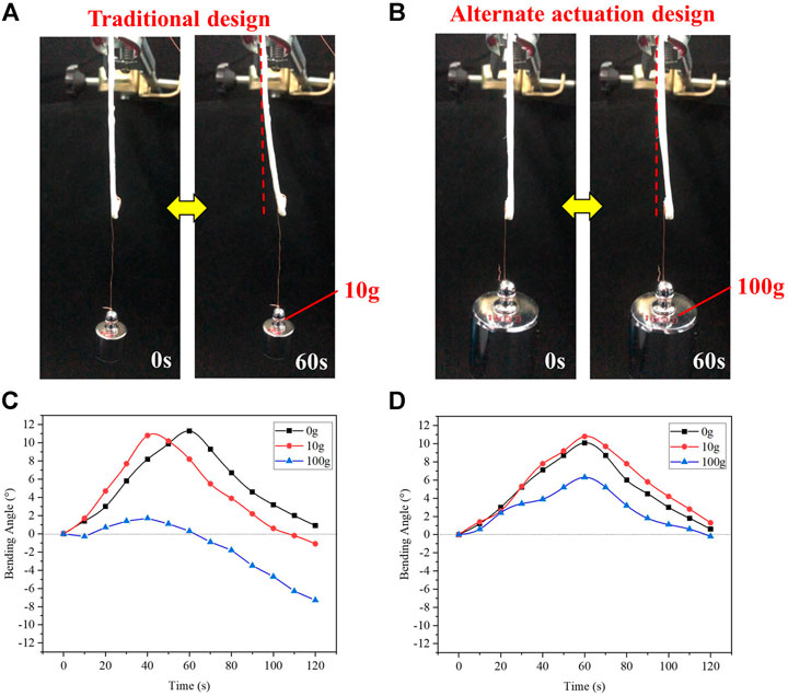
FIGURE 6. Comparison of deformation under load of traditional design and alternate-actuation design. (A) Traditional structure deformed under 10 g load. (B) Alternate-actuated structure deformed under 100 g load. (C) Bending angle as a function of time for traditional structure under different continuous loads. (D) Bending angle as a function of time for alternate-actuated structure under continuous loads.
Figure 6B shows the alternate-actuated structure swing under a 100 g load. The overall configuration of the alternate-actuated structure is the same as that of the traditional structure, but the fibers are on the opposite surfaces of the two parallel components. Figure 6D shows the deformation of the alternate-actuated structure under different loads, where the black, red, and blue curves are deformation under no load, a 10 g load, and a 100 g load, respectively. The alternate-actuated structure still swings up and down under the 100 g load without early recovery during heating and additional reverse deformation during cooling, which demonstrates that the load capacity in reversible deformation process of this structure is an order of magnitude greater than that of the traditional actuated structure. Because the dual parallel beam design allows one beam to be hot while the other is cold during the entire deformation, one beam remains in the cooling state to provide sufficient structural stiffness. The alternate-actuated structure reveals no significant mechanical defects during the two-way deformation process. The bending angle of the alternate-actuated structure is the same under no load and the 10 g load as the traditional actuated structure, and the deformation is reduced by about 50% at 100 g comparing with no-load deformation. To summarize, the alternate-actuated structure presents no significant mechanical performance defects in the two-way deformation process. It deforms reversibly under a load more than tenfold greater than what is possible with the traditional design.
Given the ability to change shape under continuous loads, the alternate-actuated structures have significant potential for use in robotic arms, load-moving devices, and posture adjustments. Figure 7A shows a walking robot that we designed to further demonstrate the potential of this technology. Each robot has six deformable legs divided into walking legs and supporting legs. The two legs in the middle are the walking legs, while the others are supporting legs. The walking legs carry the weight of the robot body and provide forward and backward propulsion during the swing phase. Therefore, the walking legs must offer sufficient structural stiffness in two-way deformations. Therefore, we designed the walking legs using the alternate-actuated parallel structure to ensure successful swinging under continuous loads in different directions.
FIGURE 7. Demonstration of walking robot. (A) Design model. (B) Photograph of walking robot. (C) Four steps in a gait cycle of walking robot. (D) Forward and backward motion of walking robot.
Figure 7B shows the fabricated walking robot. Each leg is controlled by a separate circuit to allow independent actuation. Figure 7C shows the gait of the robot, where one gait cycle requires four steps: Firstly, the support legs are heated and gradually lose their capacity to support weight. The center of gravity of the walking robot thus shifts down. The two walking legs contact the ground to maintain the structural stability together with the support legs. Secondly, the walking legs swing back. The friction force exerted on the walking legs is greater than that on the support legs, so the walking robot is pushed in the opposite direction. Thirdly, the support legs cool and gradually recover their deformation and structural stiffness, so the center of gravity of the walking robot rises and the walking legs lose contact with the ground. Finally, the walking legs recover their shape when hanging in the air and are prepared for the next stride. The total time for a gait cycle is approximately 180 s, which includes 30 s for step A, 60 s for step B, and 90 s for steps C and D. Step D, when the walking legs lose contact with the ground, starts 30 s after step C and ends at the same time as step C.
Figure 7D shows the forward and backward motion of the walking robot. The robot moves forward by 12 mm over 9 min in three gait cycles and then moves backward by 16 mm over 13 min in four gait cycles. The results show that a single gait cycle translates the robot by about 4 mm, whether the robot moves forward or backward. These results demonstrate that the alternate-actuated structures can undergo two-way deformation under continuous load and that two-way deformation produces a similar driving force. Video of the robot walking is shown in Supplementary Video S2.
The main reason of the slow walking speed is that the walking robot takes 1 min for each deformation of the walking legs. The deformation of the walking legs with the alternate-actuated structure includes the heating phase and cooling phase of the two groups of parallel components at the same time, the heating and cooling speed should be matched to ensure the consistency of their end position. It takes 1 min for the components from the actuated temperature to environment temperature, so the deformation time of the walking legs are 1 min. In order to improve the walking speed of the robot, an air-cooling system or a fluidic cooling microchannel can be integrated to reduce cooling phase in the future.
In addition, the usable range of the alternate-actuated structures are not limited to the deformation principle described herein. It can be expanded to other deformations that involve variations in structural stiffness, such as thermally driven deformations of LCE composite structures (Roach et al., 2018), photothermally driven deformation (Hua et al., 2018), and wetting- or drying-driven deformation (Baker et al., 2019).
This study proposes an alternate-actuation design to provide reversible, two-way deformation without stiffness attenuation under continuous loads. We use the design to print an actuator based on thermal mismatch to demonstrate that the deformation of two parallel components is the same for opposite actuation conditions. We develop a mathematical model to predict with 90% accuracy the bending angle for the 4D printed structure. We also propose a design strategy for the complex parallel components consisted with arbitrary curve components. The actual deformation of the parallel components is within 8% of the design value. The alternate-actuated structure can carry loads during the entire reversible deformation, and it offers a tenfold increased loading capacity compared with the traditional design. Finally, we design a walking robot to demonstrate the use of the alternate-actuation design for forward and backward translation. We use the alternate-actuation design on the swing legs and demonstrate that the legs swing normally under the multi-directional continuous loads. Thus, the robot legs deform reversibly under continuous loads, which is promising for applications involving soft robots, smart actuators, and artificial muscles.
The original contributions presented in the study are included in the article/Supplementary Material, further inquiries can be directed to the corresponding author.
GC, GS, and DZ contributed to the conception of the study; GC led the experiments with assistance from BZ and wrote the manuscript; LL, GS, and DZ. contributed significantly to analysis and manuscript preparation; All authors provided feedback.
Financial support from Key-Area Research and Development Program of Guangdong Province, China (Grant No. 2020B090923003) is gratefully acknowledged.
The authors declare that the research was conducted in the absence of any commercial or financial relationships that could be construed as a potential conflict of interest.
The Supplementary Material for this article can be found online at: https://www.frontiersin.org/articles/10.3389/fmats.2021.661593/full#supplementary-material
Akbari, S., Sakhaei, A. H., Kowsari, K., Yang, B., Serjouei, A., Yuanfang, Z., et al. (2018). Enhanced Multimaterial 4D Printing with Active Hinges. Smart Mater. Struct. 27 (6), 065027. doi:10.1088/1361-665X/aabe63
Baker, A. B., Bates, S. R. G., Llewellyn-Jones, T. M., Valori, L. P. B., Dicker, M. P. M., and Trask, R. S. (2019). 4D Printing with Robust Thermoplastic Polyurethane Hydrogel-Elastomer Trilayers. Mater. Des. 163, 107544. doi:10.1016/j.matdes.2018.107544
Bar-Cohen, Y., Carrico, J. D., and Leang, K. K. (2017). Fused Filament 3D Printing of Ionic Polymer-Metal Composites for Soft Robotics. EAPAD. 2017, 10163. doi:10.1117/12.2259782
Chen, D., Liu, Q., Han, Z., Zhang, J., Song, H., Wang, K., et al. (2020). 4D Printing Strain Self‐Sensing and Temperature Self‐Sensing Integrated Sensor-Actuator with Bioinspired Gradient Gaps. Adv. Sci. 7 (13), 2000584. doi:10.1002/advs.202000584
Cheng, C.-Y., Xie, H., Xu, Z.-y., Li, L., Jiang, M.-N., Tang, L., et al. (2020). 4D Printing of Shape Memory Aliphatic Copolyester via UV-Assisted FDM Strategy for Medical Protective Devices. Chem. Eng. J. 396, 125242. doi:10.1016/j.cej.2020.125242
Ding, Z., Weeger, O., Qi, H. J., and Dunn, M. L. (2018). 4D Rods: 3D Structures via Programmable 1D Composite Rods. Mater. Des. 137, 256–265. doi:10.1016/j.matdes.2017.10.004
Ding, Z., Yuan, C., Peng, X., Wang, T., Qi, H. J., and Dunn, M. L. (2017). Direct 4D Pprinting via Aactive Ccomposite Mmaterials. Sci. Adv. 3 (4), e1602890. doi:10.1126/sciadv.1602890
Ge, Q., Dunn, C. K., Qi, H. J., and Dunn, M. L. (2014). Active Origami by 4D Printing. Smart Mater. Struct. 23 (9), 094007. doi:10.1088/0964-1726/23/9/094007
Ge, Q., Sakhaei, A. H., Lee, H., Dunn, C. K., Fang, N. X., and Dunn, M. L. (2016). Multimaterial 4D Printing with Tailorable Shape Memory Polymers. Sci. Rep. 6, 31110. doi:10.1038/srep31110
Gladman, A. S., Matsumoto, E. A., Nuzzo, R. G., Mahadevan, L., and Lewis, J. A. (2016). Biomimetic 4D Printing. Nat. Mater. 15 (4), 413–418. doi:10.1038/nmat4544
Goo, B., Hong, C.-H., and Park, K. (2020). 4D Printing Using Anisotropic Thermal Deformation of 3D-Printed Thermoplastic Parts. Mater. Des. 188, 108485. doi:10.1016/j.matdes.2020.108485
Hua, D., Zhang, X., Ji, Z., Yan, C., Yu, B., Li, Y., et al. (2018). 3D Printing of Shape Changing Composites for Constructing Flexible Paper-Based Photothermal Bilayer Actuators. J. Mater. Chem. C. 6 (8), 2123–2131. doi:10.1039/c7tc05710e
Kim, Y., Yuk, H., Zhao, R., Chester, S. A., and Zhao, X. (2018). Printing Ferromagnetic Domains for Untethered Fast-Transforming Soft Materials. Nature. 558 (7709), 274–279. doi:10.1038/s41586-018-0185-0
Kotikian, A., Truby, R. L., Boley, J. W., White, T. J., and Lewis, J. A. (2018). 3D Printing of Liquid Crystal Elastomeric Actuators with Spatially Programed Nematic Order. Adv. Mater. 30 (10), 1706164. doi:10.1002/adma.201706164
Kuang, X., Roach, D. J., Wu, J., Hamel, C. M., Ding, Z., Wang, T., et al. (2018). Advances in 4D Printing: Materials and Applications. Adv. Funct. Mater. 29 (2), 1805290. doi:10.1002/afdm.20180529010.1002/adfm.201805290
Lee, A. Y., Zhou, A., An, J., Chua, C. K., and Zhang, Y. (2020). Contactless Reversible 4D-Printing for 3D-To-3d Shape Morphing. Virtual Phys. Prototyping 15 (4), 481–495. doi:10.1080/17452759.2020.1822189
Liu, Y., Shaw, B., Dickey, M. D., and Genzer, J. (2017). Sequential Self-Folding of Polymer Sheets. Sci. Adv. 3 (3), e1602417. doi:10.1126/sciadv.1602417
López-Valdeolivas, M., Liu, D., Broer, D. J., and Sánchez-Somolinos, C. (2018). 4D Printed Actuators with Soft-Robotic Functions. Macromol. Rapid Commun. 39 (5), 1700710. doi:10.1002/marc.201700710
Mao, Y., Ding, Z., Yuan, C., Ai, S., Isakov, M., Wu, J., et al. (2016). 3D Printed Reversible Shape Changing Components with Stimuli Responsive Materials. Sci. Rep. 6, 24761. doi:10.1038/srep24761
Momeni, F., M.Mehdi Hassani.N, S., Liu, X., and Ni, J. (2017). A Review of 4D Printing. Mater. Des. 122, 42–79. doi:10.1016/j.matdes.2017.02.068
Qiao, J., Li, Y., and Li, L. (2019). Ultrasound-assisted 3D Printing of Continuous Fiber-Reinforced Thermoplastic (FRTP) Composites. Additive Manufacturing. 30, 100926. doi:10.1016/j.addma.2019.100926
Roach, D. J., Kuang, X., Yuan, C., Chen, K., and Qi, H. J. (2018). Novel Ink for Ambient Condition Printing of Liquid Crystal Elastomers for 4D Printing. Smart Mater. Struct. 27 (12), 125011. doi:10.1088/1361-665X/aae96f
Shi, Y., Wu, H., Yan, C., Yang, X., Chen, D., Zhang, C., et al. (2020). Four-dimensional Printing – the Additive Manufacturing Technology of Intelligent Components. Chin. J. Mech. Eng-en. 56 (15), 1–25. doi:10.3901/jme.2020.15.001
Shiblee, M. N. I., Ahmed, K., Khosla, A., Kawakami, M., and Furukawa, H. (2018). 3D Printing of Shape Memory Hydrogels with Tunable Mechanical Properties. Soft Matter. 14 (38), 7809–7817. doi:10.1039/c8sm01156g
Tian, X., Wang, Q., and Li, D. (2020). Design of a Continuous Fiber Trajectory for 4D Printing of Thermally Stimulated Composite Structures. Sci. China Technol. Sci. 63 (4), 571–577. doi:10.1007/s11431-019-1485-5
Wang, Q., Tian, X., Huang, L., Li, D., Malakhov, A. V., and Polilov, A. N. (2018a). Programmable Morphing Composites with Embedded Continuous Fibers by 4D Printing. Mater. Des. 155, 404–413. doi:10.1016/j.matdes.2018.06.027
Wang, G., Cheng, T., Do, Y., Yang, H., Tao, Y., Gu, J., et al. (2018b). Printed Paper Actuator. CHI. 18 569, 1–12. doi:10.1145/3173574.3174143
Yang, C., Wang, B., Li, D., and Tian, X. (2017). Modelling and Characterisation for the Responsive Performance of CF/PLA and CF/PEEK Smart Materials Fabricated by 4D Printing. Virtual Phys. Prototyping 12 (1), 69–76. doi:10.1080/17452759.2016.1265992
Yuan, C., Roach, D. J., Dunn, C. K., Mu, Q., Kuang, X., Yakacki, C. M., et al. (2017). 3D Printed Reversible Shape Changing Soft Actuators Assisted by Liquid Crystal Elastomers. Soft Matter. 13 (33), 5558–5568. doi:10.1039/c7sm00759k
Yuan, C., Wang, F., and Ge, Q. (2021). Multimaterial Direct 4D Printing of High Stiffness Structures with Large Bending Curvature. Extreme Mech. Lett. 42, 101122. doi:10.1016/j.eml.2020.101122
Zhang, D., Zhang, G., and Li, L. (2019a). Calibration of a Six-axis Parallel Manipulator Based on BP Neural Network. Ind. Robot. 46 (5), 692–698. doi:10.1108/ir-12-2018-0248
Zhang, Y. F., Zhang, N., Hingorani, H., Ding, N., Wang, D., Yuan, C., et al. (2019b). Fast‐Response, Stiffness‐Tunable Soft Actuator by Hybrid Multimaterial 3D Printing. Adv. Funct. Mater. 29 (15), 1806698. doi:10.1002/adfm.201806698
Zhang, Q., Kuang, X., Weng, S., Zhao, Z., Chen, H., Fang, D., et al. (2020). Rapid Volatilization Induced Mechanically Robust Shape-Morphing Structures toward 4D Printing. ACS Appl. Mater. Inter. 12 (15), 17979–17987. doi:10.1021/acsami.0c02038
Zhao, S. C., Maas, M., Jansen, K., and van Hecke, M. (2019). 3D Printed Actuators: Reversibility, Relaxation, and Ratcheting. Adv. Funct. Mater. 29 (51), 1905545. doi:10.1002/adfm.201905545
Keywords: 4D printing, design method, alternate actuation, loading capacity, reversible deformation
Citation: Chu G, Zhou B, Shao G, Zhang D and Li L (2021) Four-Dimensional Printing of Alternate-Actuated Composite Structures for Reversible Deformation under Continuous Reciprocation Loading. Front. Mater. 8:661593. doi: 10.3389/fmats.2021.661593
Received: 31 January 2021; Accepted: 03 May 2021;
Published: 18 May 2021.
Edited by:
Yusheng Shi, Huazhong University of Science and Technology, ChinaReviewed by:
Yanjie Wang, Hohai University, ChinaCopyright © 2021 Chu, Zhou, Shao, Zhang and Li. This is an open-access article distributed under the terms of the Creative Commons Attribution License (CC BY). The use, distribution or reproduction in other forums is permitted, provided the original author(s) and the copyright owner(s) are credited and that the original publication in this journal is cited, in accordance with accepted academic practice. No use, distribution or reproduction is permitted which does not comply with these terms.
*Correspondence: Longqiu Li, bG9uZ3FpdWxpQGhpdC5lZHUuY24=
Disclaimer: All claims expressed in this article are solely those of the authors and do not necessarily represent those of their affiliated organizations, or those of the publisher, the editors and the reviewers. Any product that may be evaluated in this article or claim that may be made by its manufacturer is not guaranteed or endorsed by the publisher.
Research integrity at Frontiers
Learn more about the work of our research integrity team to safeguard the quality of each article we publish.