
94% of researchers rate our articles as excellent or good
Learn more about the work of our research integrity team to safeguard the quality of each article we publish.
Find out more
ORIGINAL RESEARCH article
Front. Mater. , 28 May 2021
Sec. Smart Materials
Volume 8 - 2021 | https://doi.org/10.3389/fmats.2021.659441
This article is part of the Research Topic Four-dimensional (4D) Printing View all 11 articles
 Kai Liu1,2
 Qingqing Zhang2
 Chenyang Zhou2
 Yusheng Shi3
 Ce Sun4
 Huajun Sun1,2,4*
 Changxia Yin4
 Jiaming Hu2Shuyu Zhou2Yuzhen Zhang2Yu Fu2
Lead zirconate titanate (PZT) piezoelectric composites used in transducers were fabricated via direct ink writing (DIW) combined with furnace sintering and resin impregnation. A ceramic slurry with a volume fraction of 52 vol% and suitable viscoelasticity was prepared. After post-process, the PZT ceramic specimens showed a nanoscale grain size with a density of 7.63 g/cm3, accounting for 97.8% of the theoretical density. The effects of different printing rod spacing on the electrical properties of composites were evaluated and lucubrated. Finally, an underwater acoustic transducer was assembled by using the PZT piezoelectric composites fabricated by the above method. The electrical signal generated by the underwater acoustic transducer changed autonomously with the acoustic stimulation, which indicated the application mode of 4D printing in functional devices in the future.
Underwater acoustic transducer is a kind of functional device that can convert acoustic and electrical signals into each other and its core component is piezoelectric composite material (Tian et al., 2021; Li et al., 2006; Rouffaud et al., 2015). Compared with 0–3, 1–3 and, 2–3 piezoelectric composites, 3–3 ceramic/polymer composites have a bi-continuous architecture comprising an active ferroelectric ceramic phase and a passive flexible polymer phase, which possess high hydrostatic pressure sensitivity and good coupling properties with water, thereby improving the bandwidth and transmitting and receiving sensitivity of the transducer (Newnham et al., 1978; Tressler et al., 1999; Bowen and Topolov, 2003). But traditional fabricating methods, such as the self-assembly method (Liu et al., 1996), the gel-casting method, the cutting-filling method (Viganò et al., 2017) and so on, have certain disadvantages like low material utilization, long production cycles and limited product complexity (Woodward et al., 2015).
Additive manufacturing (AM) technology has the advantage of being easy to prepare complex structural parts, including direct ink writing (DIW), digital light processing (DLP), selective laser sintering (SLS) and other methods. The principle of DIW is to extrude viscoelastic ink from the needle head to form rod-shaped fibers. As the needle head moves, the rod-shaped fibers are deposited into a specific pattern (Revelo and Colorado, 2018; Coppola et al., 2021). DLP technology is to project patterned ultraviolet light onto the photocurable material to cure each single layer, and form a specific shape through the superimposition of layers (Wang et al., 2019; Li et al., 2021). In SLS technology, a laser is used to melt the binder and bond the ceramic powder to form (Kai et al., 2020). Compared with the DLP and SLS processes, the DIW process has the advantages of simple forming equipment, easy preparation of slurry, and high solid content of the printed green body (An et al., 2020). Recently, AM process combined with smart materials is also called 4D printing and piezoelectric materials are a typical type of smart materials (Kong et al., 2014; Kuang et al., 2019). Therefore, this research belongs to the category of 4D printing ceramics. Some researchers have tried to investigate 4D printing of ceramics in recent years. Liu et al. (2018) took the lead in researching ceramic 4D printing, where DIW was used to print a special precursor for ceramics. Firstly, the main structure was printed on a prestressed elastic substrate. When the prestress of the substrate disappears, the main structure is deformed accordingly and became a preset shape. After heating treatment, the required ceramic body was obtained. In this research, “shape change” of ceramic components is realized by using the elasticity of the composites in 4D printing. Grinberg et al. (2018) combined barium titanate (BTO) material with fused deposition technology, and BTO piezoelectric composites were 4D printed for making sensors, which can be implanted into the human body to achieve the function and effect of real-time detection of the force between prosthesis bones. However, there is a lack of exploration of the performance changes caused by the special structure of piezoelectric composites. Zeng et al. (2020) printed 1–3 BTO piezoelectric composite with honeycomb structure through 4D printing by combining BTO material with DLP technology. The structure can increase the acoustic performance of the piezoelectric ceramic, realize the function of ultrasonic sensing. However, due to the limitation of the piezoelectric composite structure, the voltage efficiency is only 0.1%. Compared with BTO ceramics, lead zirconate titanate (PZT) ceramics also have a higher piezoelectric coefficient and are more suitable to be used as a transducer matrix material (Palmero and Bollero, 2020). Chen et al. (2017) and Yan et al. (2018) prepared PZT piezoelectric ceramics columnar array through DLP technology and assembled PZT-based ultrasonic sensors with good sensing effects. However, due to the high acoustic impedance of piezoelectric ceramics, it is not easy to match the acoustic impedance of water, which limits the underwater application of the ultrasonic transducer. At present, there are few studies on the performance and functional changes of 4D printed PZT piezoelectric composites transducer. Through editing the structure and composition of piezoelectric composites freely. 4D printing of electroactive materials including piezo-composites will present a revolutionary significance of fabricating more excellent and flexible piezoelectric materials.
This research aims to present 4D printing of PZT composites transducer based on the DIW process. PZT slurry with high solid content was designed and prepared and the influence of dispersant on the rheological properties of the slurry was explored. Multiple sets of piezoelectric ceramic skeletons were prepared, and the extruded rod fibers were arranged at different intervals. The electrical properties of the piezoelectric composites with different rod spacing were discussed. Finally, the output voltage evolution stimulated by the vibration of acoustic waves was presented in an underwater environment.
Figure 1 shows the fabricating route of underwater acoustic transducers. The PZT ceramic skeleton was printed by DIW method, and epoxy resin was filled into the skeleton to prepare piezoelectric composites. and then the piezoelectric composites were prepared into an underwater acoustic transducer.
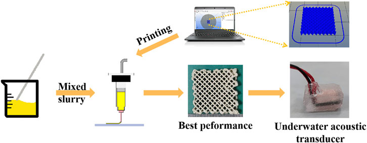
FIGURE 1. The fabricating route of underwater acoustic transducers.
First, the raw PZT powder was ball milled to refine the particle size. Trisodium citrate was added as a dispersant into ethanol to prepare a premixed solution. The surfaces of the particles were quickly wetted by dispersants, which increased the energy barrier between the particles in order to eliminate the agglomeration (Walton et al., 2020). After ball milling, the mixture was filtered and dried. Finally, the PZT powder with a particle size of d50: 523 nm was obtained as shown in Figure 2. After powder preparation, a 10 wt% polyvinyl alcohol (PVA) aqueous solution containing PZT powder was prepared. The solution also contains a certain amount of ammonium polyacrylate (PAA-NH4) or sodium polyacrylate homopolymer (PAAS) as dispersant, and 1.75 wt% glycerin as lubricant. After stirring, the slurry was aged for 2 h before printing.

FIGURE 2. SEM micromorphology of PZT powder.
The model was sliced by the slicing software (Ultimaker Cura 4.1) to generate a Gcode file and the movement of the printer needle head is controlled by the program including layer information. The slurry was extruded from the syringe system and the power was supplied by an air pump with a pressure of 0.2 MPa. Figure 3 shows the direct ink writing 3D printing device and its sketch map. The height of the syringe is 115 mm, and its moving speed is set to be 8 mm/s.
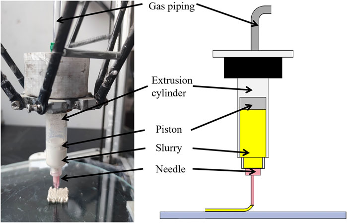
FIGURE 3. Direct ink writing 3D printing device and sketch map.
A suitable extrusion needle head is extremely important in the printing process. The smaller the needle head size is, the greater pressure is needed for extrusion. Inversely, if the size of the needle head is too large, it might result in poor printing accuracy. The height of the layer is also an important parameter of printing. If the layer height is too low, the needle head will walk in the previously extruded slurry and cause accumulation. If the height of each layer is too high, the slurry stacking will be misaligned. The diameter of the needle used in this study was 0.6 mm and the height of the printing layer was 0.3 mm, so that it exists no excess drags or accumulation on each extruded fiber.
The stacking directions of the rods between the layers were perpendicular to each other and the size of the woodpile structure designed by 3D modeling software was set to be 20 × 20 × 5 mm. Due to the viscoelasticity of the slurry, a gap could be formed between the rods in the height direction, and the shape of the model maintained. Since there were few volatile substances in the slurry, the green body shrunk insignificantly after drying.
The debinding and sintering of the green body were carried out separately to prevent the piezoelectric properties of PZT ceramics from being reduced due to lead volatilization. First, the green body was burned in air to fully discharge the organic phase, and then it underwent a high temperature sintering in a lead-rich environment. The debinding curve was developed by analyzing the TG-DSC curve in Figure 4.
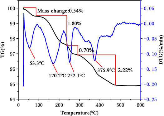
FIGURE 4. Thermal decomposition curve of the green body in the air.
As can be seen from the figure, the decomposition of the organic phase in the ceramic is substantially completed when the temperature reached 700°C. The debinding process was designed to heat up to 700°C at a heating rate of 1°C/min, which could avoid the cracks during the debinding process. By holding the temperature at 170, 250, 375, and, 600°C for 1 h separately, the organic phase can fully react with oxygen and be discharged. The whole debinding process is shown in Figure 5. The sintering process was carried out in a sealed crucible, and sufficient PZT powder was used to surround the printed body, thereby providing lead-rich vapor. The sintering temperature increased from room temperature to 1250°C at a rate of 3°C/min, and kept it for 4 h, so that the crystal grains could grow sufficiently. Finally, the sintered body was cooled to room temperature in the furnace.
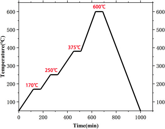
FIGURE 5. Debinding temperature-time curve.
E51 epoxy resin and curing agent were mixed uniformly according to the mass ratio of 4:1, and the polished ceramic skeleton was immersed in the mixture. The epoxy resin can be cured within 1 h at 50°C. The shrinkage during the curing process will produce mechanical stress, which will combine the epoxy resin with the ceramic skeleton. At the same time, due to the porous property of ceramic skeleton, the combination of epoxy resin and ceramic skeleton can be very stable. After the resin was cured, the top and bottom surfaces of the piezoelectric composite were polished to make them parallel, and the ceramic part of the composites was exposed on the surface.
The top and bottom surfaces of samples were both coated with low-temperature silver slurry and then dried at 110°C for 30 min to form the silver electrode. The sample was connected to a dielectric strength tester and immersed in polymethyl silicone oil which was heated to 80°C. Then the sample was polarized under a 2.5 kV/mm polarization field strength for 30 min. After that, it was deposited at room temperature for 24 h until the discharge was completed before performance testing.
A laser particle size analyzer (Mastersizer 2000) was used to measure the particle size distribution of the ball milled PZT powder. In addition, the MCR101 dynamic shear rheometer was used to measure the rheological properties of the slurry. The German Netzsch STA449F5 thermogravimetric analyzer was used to heat the sample to 600°C at a heating rate of 10°C/min to measure the weight loss of the printed body. Scanning electron microscope (SEM) was used to observe the cross section of the sintered part. The surface and cross-sectional morphology of the polished piezoelectric composites was observed by an optical microscope. The structural composition was investigated by X-ray diffractometer (Empyrean). The longitudinal piezoelectric strain coefficient (d33), dielectric constant (εr) and dielectric loss (tanδ) were investigated by piezometer (ZJ-3 quasi-static d33 tester) and Novocontrol test system (Concept 80, Germany). Three samples were made for each group of variables, and performance tests were performed on each sample three times. The average of the above test results was used as the final value.
The printability of the slurry is mainly determined by its rheological behavior. In DIW process, a non-Newtonian fluid slurry with viscoelasticity is usually needed. The viscous component allows the slurry to be smoothly extruded through the needle head, while the elastic component gives the extruded filament shape-retention ability and sufficient mechanical strength to support the weight of the subsequent layer (Revelo and Colorado, 2018). Using the synergistic hydrogen bonds between some macromolecules and polymer chains formed by in-situ polymerization, high-strength hydrogels with non-Newtonian fluid characteristics can be constructed in the slurry. Using PVA as a macromolecular template, PVA-PAA gel can be obtained by in-situ polymerization of acrylic acid (AA). The gel has a three-dimensional grid structure (Lewis, 2010), which can be bound with PZT powder to enhance the elastic strength of the slurry and reduce the viscosity of the slurry (Chen et al., 2017; Rac. et al., 2019; Wu et al., 2020).
PVA and acrylic additives were added to the slurry as binder and dispersant respectively, and the influence of the type and content of the dispersant on the viscosity of the slurry was investigated. First, the influence of two dispersants (PAA-NH4 and PAAS) on the viscosity of the slurry was explored. Rheological properties of PZT slurry with the same mass fraction were compared under the conditions of no dispersant, 1.25% PAA-NH4, 1.25% PAAS and the mixture of two dispersants. Figure 6A shows the curve of shear stress versus shear rate, which is close to the shape and direction of the shear rate-shear stress curve of classical shear thinning fluid. It shows that the slurries with different types of dispersants all have shear thinning behavior characteristics. Compared to the viscosity levels of each slurry in Figure 6B, it can be seen that PAA-NH4 reduces the viscosity of the slurry significantly better than other dispersants. When two dispersants are added at the same time, due to the large amount of PVA-PAA gel formed in the slurry, the amount of three-dimensional grid increases, which makes the viscosity of the slurry increase instead.
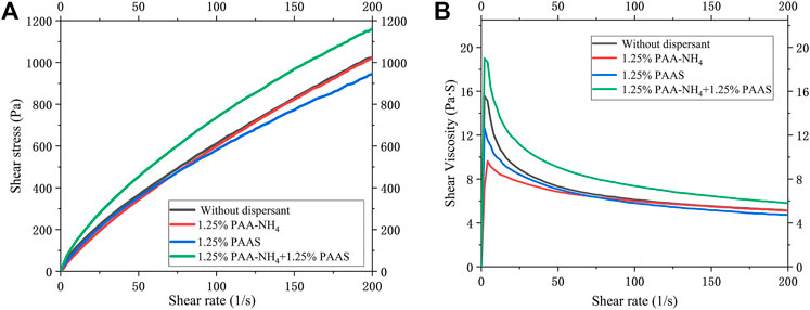
FIGURE 6. (A) Variation curve of stress versus shear rate of PZT slurry with different dispersants; (B) Variation curve of viscosity versus shear rate of PZT slurry with different dispersants.
Furthermore, PAA-NH4 was used as a dispersant to explore the most suitable addition amount. The rheological properties of the slurry in the range of 0.75∼2% of the dispersant added were measured, and the results are shown in Figure 7A. It can be seen that the slurries with different add amounts of dispersant all have shear thinning behavior, and the initial viscosity is not much different.
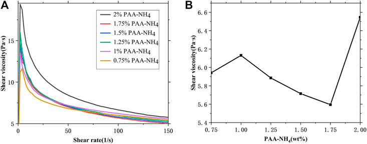
FIGURE 7. (A) Shear rate-shear viscosity change curve of gradient dispersant content; (B) Viscosity change curve of gradient slurry concentration at 105 s−1 shear rates.
According to the actual situation in the extrusion process, rheological data with practical significance was selected for comparison within the appropriate shear rate range. The shear rate γ of the fluid passing through the conical needle can be calculated by the following formula (M’Barki et al., 2017; Nan et al., 2018).
In the formula, Q is the volume flow and R is the radius of the needle. In the printing process, we used a needle with a diameter of 0.60 mm and a printing speed of 8 mm/s. Therefore, according to this formula, the extrusion force during the extrusion process was equivalent to a shear rate of 104.92 s−1 applied to the slurry. The rheological data of the shear viscosity flow curve when the shear rate of the gradient dispersant slurry was 105 s−1 was collected, as illustrated in Figure 7B. At this shear rate, the slurry with 2 wt% PAA-NH4 has the highest viscosity. This is because a large amount of gel grid has generated in the slurry, and the shear force required to destroy the grid structure is also greater. The slurry added with 1.75 wt% of PAA-NH4 has a lower viscosity, so the extrusion effect of the slurry is the best under this dispersant content.
The phase and microstructure of ceramics at different sintering temperatures were analyzed. The cross-sections SEM images of the samples sintered at different sintering temperatures are shown in Figure 8. It can be seen from the figure that when the sintering temperature is 1240°C, the crystal grains are not fully grown. And there is a liquid phase between the grain boundaries, resulting in a small crystal grain size with a maximum size of 9.98 μm. When the temperature is raised to 1250°C, the grain size increases (the maximum size is 19.1 μm), and the grain boundaries are clear. The actual density of the sintered sample is 7.63 g/cm3 and the relative density is 97.8%. As the temperature further increased, the small crystal grains grew further, but when the temperature raised to 1270°C, the grain boundaries were remelted due to the high temperature, resulting in unclear grain boundaries.
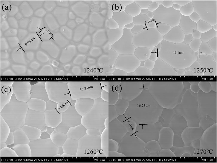
FIGURE 8. Cross-section morphology and grain size of samples sintered at (A) 1240°C, (B) 1250°C, (C) 1260°C and (D) 1270°C.
It can be seen from Figure 9 that when the sintering temperature is 1240°C and the heat preservation time is 4 h, the phase structure of ceramics has split peaks in the range of 2θ = 21∼22.5° and 43∼45°, which shows that the ceramic is in the quasi-homotype phase boundary area where the tripartite phase and the tetragonal phase coexist. And the phase diagram has a split peak at 2θ = 32°, indicating that the ceramic has a pyrochlore phase structure when the firing temperature is low, and a tripartite perovskite structure can’t be formed. However, as the temperature increased to 1250∼1270 C, the pyrochlore phase structure in the sintered body is eliminated, and the pure tripartite perovskite structure is formed. From the results of grain growth and phase analysis, 1250∼1260°C is the best sintering temperature range.
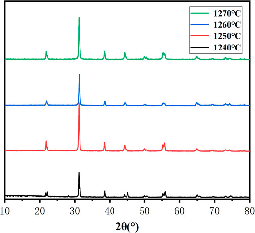
FIGURE 9. X-ray diffraction pattern of ceramics sintered at 1240, 1250, 1260 and 1270°C.
The influence of structural parameters on the properties of piezoelectric composites was discussed by changing rod spacing of the ceramic skeleton. The filling density was respectively set to 20, 23, 26, and 29%, and the printing effect of the piezoelectric ceramic skeleton is shown in Figures 10A–H. After filling the resin, an optical microscope was used to measure the distance between the piezoelectric composite rods, and the corresponding rod spacing was 1.34, 1.20, 0.86, 0.66 mm, as shown in Figures 10I–L. Since the overall structure shrinks uniformly after sintering, the size in Figure 10N can be used to calculate the rod diameter and layer height shrinkage. Through calculation, the diameter shrinkage rate of the rod is 30%. After the prepared 3–3 piezoelectric composite was polished and polarized, its piezoelectric constant (d33) and relative dielectric constant (ɛr) were tested. These performance test data were used to characterize the influence of the distance between the rods on the performance of the piezoelectric composites.
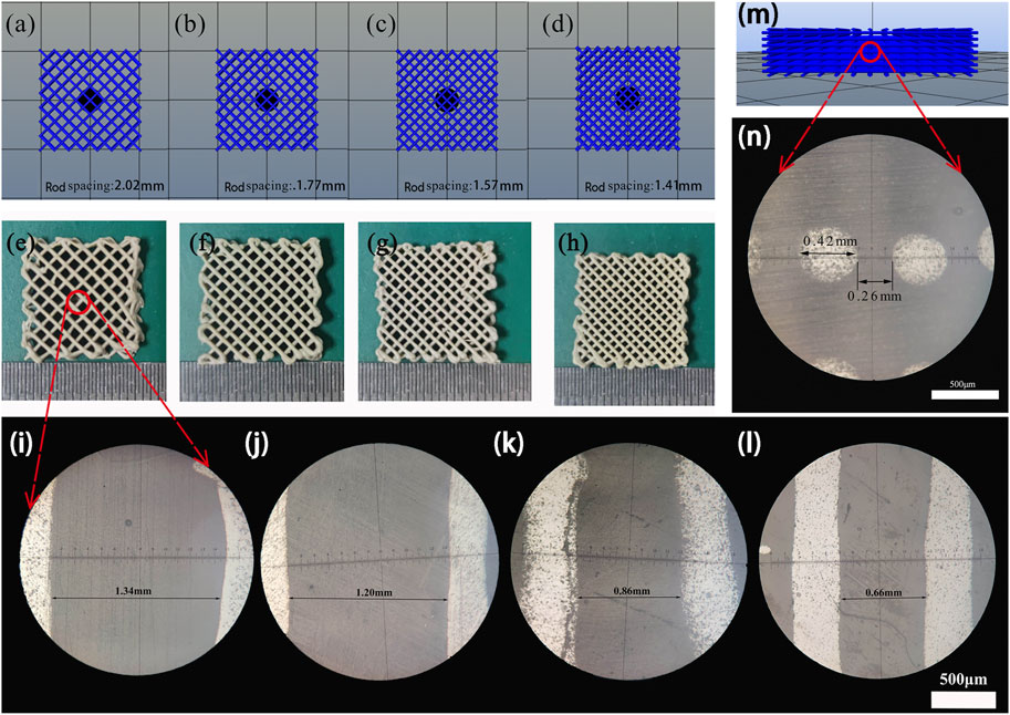
FIGURE 10. (A, E, I) 20% filling density model, sintered body and size micrograph; (B, F, J) 23% filling density model, sintered body and size micrograph; (C, G, K) 26% filling density model, sintered body and size micrograph; (D, H, L) 29% filling density model, sintered body and size micrograph; (M, N) Model cross section and size micrograph.
The d33 and relative permittivity of the 3–3 piezoelectric composites were tested as a function of the distance between the rods. As shown in Figure 11, the error bars in the figure indicate the maximum and minimum values of the piezoelectric coefficient and the relative permittivity of the sample. Within the range of 0.66∼1.34 mm rod spacing, both d33 and ɛr increase first and then decrease. When the rod spacing is 0.86 mm, the electrical performance reaches the maximum, the maximum d33 is 103 pC/N, and ɛr is 274.34, and the smaller the dielectric constant is, and the smaller the dielectric constant of the piezoelectric composites, the smaller the dielectric loss. This is because as the distance between the rods increases, the content of the ceramic phase decreases accordingly. When the composites are under stress, the greater the force acting on the piezoelectric ceramic frame, the more surface induced charges are generated (Runt et al., 1985; Liu et al., 2017; Jin et al., 2020; Wu et al., 2020). However, with the further decrease of the rod spacing, the piezoelectric and dielectric decrease. This is because as the distance between the rod decreases, there is overlap in the vertical direction during the printing process, which converts the precise 3–3 type into piezoelectric composites with other structures (Liu et al., 2017). This leads to the formation of internal closed cells inside the ceramic part after sintering and increases the number of defects. This phenomenon means that the internal pores of the ceramic parts can’t be filled and the polarization process is affected, resulting in an increase in tanδ (Runt et al., 1985).
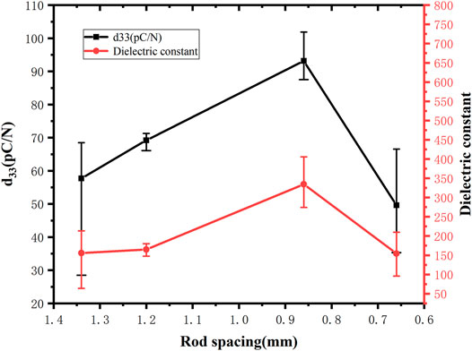
FIGURE 11. The change curve of d33 and relative permittivity of piezoelectric composites with diffrente rod spacings.
Through this investigation, it is found that the reduction of the rod spacing has the law of first increasing and then decreasing in the electrical properties of the 4D printed 3–3 piezoelectric composites. Therefore, with the help of 4D printing technology, we can freely design and change the structural parameters, and explore the influence rules of the parameters, so as to regulate the performance of the structure to meet the controllable changes in performance and functions.
The underwater acoustic transducer uses piezoelectric composites with copper foil adhered to the surface as the piezoelectric element. At the same time, Polyurethane (PU) is used as the matching layer of the transducer because of its acoustic impedance close to that of water (Sasikumar et al., 2014; Bian et al., 2020; Yf et al., 2021). In order to characterize the sound-to-electric conversion function of the manufactured underwater acoustic transducer, a test scene as shown in Figure 12 was constructed to verify. A signal generator was used to generate electrical signals with different waveforms and frequencies. The signals were then inputted into the speaker to make it emit sound signals of the same waveform and frequency. The distance between the speaker and the sensor is 450 mm, and the sound wave signal generated by the speaker was converted into an electric signal by the underwater acoustic transducer, and the electric signal was displayed on a digital oscilloscope.
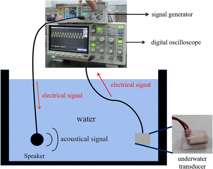
FIGURE 12. Signal receiving test of underwater acoustic transducer.
Under the input voltage (Vi) of 2∼24 V, the loudspeaker can emit 100 kHz and with different amplitudes acoustic signals. After receiving the acoustic signal, the underwater acoustic transducer converts it into a response voltage (VPP), as shown in Figure 13A VPP is positively related to Vi. When the input voltage was 24 V, the output voltage was 162 mV, and the voltage conversion efficiency was 0.675%. The demonstration results show that the acoustic electrical conversion of piezoelectric materials in water can be realized by 4D printing. Through changing the structural parameters of piezoelectric composites, the conversion efficiency of the transducer also changes accordingly. Under the optimal printing parameters, the prepared underwater acoustic transducer can generate a maximum voltage of 162 mV. At the same time, through the change of the waveform displayed on the oscilloscope, people can detect the change of the underwater sound source, so as to get a warning.
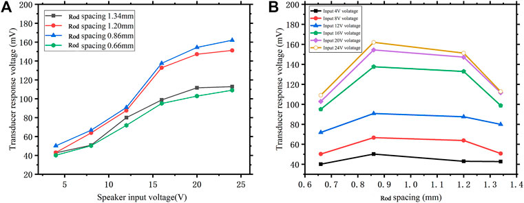
FIGURE 13. (A) Comparison of signal generator input and digital oscilloscope output; (B) The peak-to-peak Vpp response of the underwater acoustic transducer at 100 kHz varies with the output voltage of the signal generator.
Above all, this 4D printing method can quickly and autonomously control the printing structure and realize the detection of controllable changes, which is an advantage that traditional manufacturing methods do not have. And in the future, it can be used to prepare optimized piezoelectric structures to further improve the performance of underwater acoustic transducers, which is expected to lead the development direction of 4D printing functional devices.
This article presents the application of 4D printing in underwater acoustic transducers. The combination of piezoelectric material PZT and direct ink writing is conducive to the development of underwater detection intelligent equipment with high performance and multi-function. The specific conclusions are as follows,
1. The PZT piezoelectric ceramic skeleton was prepared by direct ink writing. The influence of the dispersant on the viscosity of the slurry was explored. It was found that when the addition amount of the dispersant ammonium polyacrylate in the slurry is 1.75 wt%, the slurry has the best printing effect. In addition, the green body has the best sintering effect at 1250∼1260°C, which can form a pure trigonal perovskite structure, the relative density after sintering reaches 97.8%.
2. The performance of piezoelectric composites with different rod spacing was tested. As the distance between the rods decreases, the d33 and ɛr of the piezoelectric composite first increase and then decrease. When the filling density was 26%, the printed structure had the best electrical performance (d33 = 103 pC/N and ɛr = 274.34).
3. A 4D printed sample was used to prepare an underwater acoustic transducer. Piezoelectric composites with the best electrical performance also have the highest voltage output, and the output voltage maximum was 162 mV. This verifies that this 4D printing method can quickly achieve structural changes, thereby obtaining the best performance.
Therefore, it is necessary to further explore the advantages of using 4D printing technology to realize the free design of piezoelectric structures, and manufacturing of piezoelectric composites. These piezoelectric devices have independently adjustable piezoelectric characteristics and functions, which have great potential for underwater detection and communication applications.
The original contributions presented in the study are included in the article/Supplementary Material, further inquiries can be directed to the corresponding author.
Experiments were designed by KL. QZ completed the main experimental part. CZ and CS, designed the slurry formula; CY and JH, performed performance tests on experimental samples; SZ, YZ, and YF designed and assembled a 3D printer. The main paper was written by QZ and KL revised the paper. All authors discussed the results and their implications, participated in the revised manuscripts at various stages, and approved for publication.
This work was supported by the National Innovation and Entrepreneurship Training Program for College Students (202010497012), self-determined and innovative research funds of WUT (2020-CL-B1-05), the National Natural Science Foundation of China (Grant Nos. U1806221, 51672198), Innovation and Development Project of Zibo City (2017CX01A022), Instruction & Development Project for National Funding Innovation Demonstration Zone of Shandong Province (2017-41-1, 2017-41-3, 2018ZCQZB01, 2019ZCQZB03), Central Guiding Local Science and Technology Development Special Funds (Grant Nos. 2060503), and Key Research & Design Program of Shandong Province (2019GGX102011).
The authors declare that the research was conducted in the absence of any commercial or financial relationships that could be construed as a potential conflict of interest.
An, T., Hwang, K. T., Kim, J. H., and Kim, J. (2020). Extrusion-based 3D Direct Ink Writing of NiZn-Ferrite Structures with Viscoelastic Ceramic Suspension[J]. Ceramics Int., 46(5):6469–6476. doi:10.1016/j.ceramint.2019.11.127
Bian, J., Wang, Y., Liu, Z., Shen, M., Zhao, H., Sun, Y., et al. (2020). Ultra-wideband Underwater Acoustic Transducer with a Gradient Impedance Matching Layer[J]. Appl. Acoust. 175. doi:10.1016/j.apacoust.2020.107789
Bowen, C. R., and Topolov, V. Y. (2003). Piezoelectric Sensitivity of PbTiO3-Based Ceramic/polymer Composites with 0-3 and 3-3 Connectivity. Acta Materialia 51 (17), 4965–4976. doi:10.1016/S1359-6454(03)00283-0
Chen, K., Liu, J., Yang, X., and Zhang, D. (2017). Preparation, Optimization and Property of PVA-HA/PAA Composite Hydrogel. Mater. Sci. Eng. C 78 (sep), 520–529. doi:10.1016/j.msec.2017.04.117
Coppola, B., Tardivat, C., Richaud, S., Tulliani, J.-M., Montanaro, L., and Palmero, P. (2021). 3D Printing of Dense and Porous Alkali-Activated Refractory Wastes via Direct Ink Writing (DIW). J. Eur. Ceram. Soc. 41, 3798–3808. doi:10.1016/j.jeurceramsoc.2021.01.019
Grinberg, D., Siddique, S., Le, M. Q., Liang, R., Capsal, J. F., and Cottinet, P. J. (2018). 4D Printing Based Piezoelectric Composite for Medical Applications. J. Polym. Sci. Part. B: Polym. Phys. 57 (3), 109–115. doi:10.1002/polb.24763
Jin, C., Hao, N., Xu, Z., Trase, I., Nie, Y., Dong, L., et al. (2020). Flexible Piezoelectric Nanogenerators Using Metal-Doped ZnO-PVDF Films. Sensors Actuators A: Phys. 305, 111912. doi:10.1016/j.sna.2020.111912
Kai, L., Jiang, W., Tian, W., and Huajun, S. (2020). Effects of Carbon Content on Microstructure and Mechanical Properties of SiC Ceramics Fabricated by SLS/RMI Composite Process - ScienceDirect[J]. Ceramics Int. 46 (14), 22015–22023. doi:10.1016/j.ceramint.2020.05.18
Kong, Y. L., Tamargo, I. A., Kim, H., and Kim, J. (2014). 4D Printing: Multi-Material Shape Change[J]. Architectural Des. 84 (1), 116–121. doi:10.1002/ad.1710
Kuang, X., Roach, D. J., Wu, J., Hamel, C. M., Ding, Z., Wang, T., et al. (2019). Advances in 4D Printing: Materials and Applications[J]. Adv. Funct. Mater. 29 (2), 1805290.1–1805290.23. doi:10.1002/adfm.201805290
Lewis, J. A. (2010). Colloidal Processing of Ceramics. J. Am. Ceram. Soc. 83 (10), 2341–2359. doi:10.1111/j.1151-2916.2000.tb01560.x
Li, D., Wu, M., Oyang, P., and Xu, X. (2006). Cymbal Piezoelectric Composite Underwater Acoustic Transducer. Ultrasonics 44 (8), e685–e687. doi:10.1016/j.ultras.2006.05.127
Li, Y., Mao, Q., Yin, J., Wang, Y., Fu, J., and Huang, Y. (2021). Theoretical Prediction and Experimental Validation of the Digital Light Processing (DLP) Working Curve for Photocurable Materials. Additive Manufacturing 37, 101716. doi:10.1016/j.addma.2020.101716
Liu, G., Zhao, Y., Wu, G., and Lu, J. (2018). Origami and 4D Printing of Elastomer-Derived Ceramic Structures[J]. Sci. Adv. 4 (8), eaat0641. doi:10.1126/sciadv.aat0641
Liu, J., Kim, A. Y., Wang, L. Q., Palmer, B. J., Chen, Y. L., Bruinsma, P., et al. (1996). Self-assembly in the Synthesis of Ceramic Materials and Composites. Adv. Colloid Interf. Sci., 69, 131–180. doi:10.1016/S0001-8686(96)00309-0
Liu, W., Lv, L., Li, Y., Wang, Y., Wang, J., Xue, C., et al. (2017). Effects of Slurry Composition on the Properties of 3-1 Type Porous PZT Ceramics Prepared by Ionotropic Gelation - ScienceDirect[J]. Ceramics Int. 43 (8), 6542–6547. doi:10.1016/j.ceramint.2017.02.079
M’Barki, A., Bocquet, L., and Stevenson, A. (2017). Linking Rheology and Printability for Dense and Strong Ceramics by Direct Ink Writing[J]. Scientific Rep. 7 (1), 6017. doi:10.1038/s41598-017-06115-0
Meng, X., Xu, J., Zhu, J., et al. (2020). Porous yttria-stabilized zirconia ceramics with low thermal conductivity via a novel foam-gelcasting method. J. Mater. Sci. 55. doi:10.1007/s10853-020-04900-3
Nan, B., Olhero, S., Pinho, R., Vilarinho, P. M., Button, T. W., and Ferreira, J. M. F. (2018). Direct Ink Writing of Macroporous lead‐free Piezoelectric Ba 0.85 Ca 0.15 Zr 0.1 Ti 0.9 O 3. J. Am. Ceram. Soc. 102 (7633), 3191–3203. doi:10.1111/jace.16220
Newnham, R. E., Skinner, D. P., and Cross, L. E. (1978). Connectivity and Piezoelectric-Pyroelectric Composites. Mater. Res. Bull. 13 (5), 525–536. doi:10.1016/0025-5408(78)90161-7
Palmero, E. M., and Bollero, A. (2020). 3D and 4D Printing of Functional and Smart Composite Materials[J]. Reference Module in Materials Ence and Materials Engineering. doi:10.1016/b978-0-12-819724-0.00008-2
Rac, V., Lević, S., Balanč, B., Olalde Graells, B., and Bijelić, G. (2019). PVA Cryogel as Model Hydrogel for Iontophoretic Transdermal Drug Delivery Investigations. Comparison with PAA/PVA and PAA/PVP Interpenetrating Networks. Colloids Surf. B Biointerfaces 180, 441–448. doi:10.1016/j.colsurfb.2019.05.017
Revelo, C. F., and Colorado, H. A. (2018). 3D Printing of Kaolinite clay Ceramics Using the Direct Ink Writing (DIW) Technique. Ceramics Int. 44, 5673–5682. doi:10.1016/j.ceramint.2017.12.219
Rouffaud, R., Granger, C., Hladky-Hennion, A.-C., Thi, M.P., and Levassort, F. (2015). Tonpilz Underwater Acoustic Transducer Integrating Lead-free Piezoelectric Material. Phys. Proced. 70, 997–1001. doi:10.1016/j.phpro.2015.08.208
Runt, J., Safari, A., Galgoci, E. C., and Newnham, R. E. (1985). The Influence of Interfacial Adhesion on the Piezoelectric Response of Electroceramic/polymer Composites. Ferroelectrics Lett. Section 5, 15–20. doi:10.1080/07315178508202461
Sasikumar, K., Manoj, N. R., Mukundan, T., and Khastgir, D. (2014). Design of XNBR Nanocomposites for Underwater Acoustic Sensor Applications: Effect of MWNT on Dynamic Mechanical Properties and Morphology. J. Appl. Polym. Sci., 131(8):a-n. doi:10.1002/app.40752
Tian, F., Liu, Y., Ma, R., Li, F., Xu, Z., and Yang, Y. (2021). Properties of PMN-PT Single crystal Piezoelectric Material and its Application in Underwater Acoustic Transducer. Appl. Acoust. 175 (4), 107827. doi:10.1016/j.apacoust.2020.107827
Tressler, J. F., Alkoy, S., Dogan, A., and Newnham, R. E. (1999). Functional Composites for Sensors, Actuators and Transducers. Composites A: Appl. Sci. Manufacturing 30 (4), 477–482. doi:10.1016/S1359-835X(98)00137-7
Viganò, F., Cristiani, C., and Annoni, M. (2017). Ceramic Sponge Abrasive Waterjet (AWJ) Precision Cutting through a Temporary Filling Procedure. J. Manufacturing Process. 28 (1), 41–49. doi:10.1016/j.jmapro.2017.05.014
Walton, R. L., Fanton, M. A., Meyer, R. J., and Messing, G. L. (2020). Dispersion and Rheology for Direct Writing lead‐based Piezoelectric Ceramic Pastes with Anisotropic Template Particles. J. Am. Ceram. Soc. 103, 6157–6168. doi:10.1111/jace.17350
Wang, L., Luo, Y., Yang, Z., Dai, W., Liu, X., Yang, J., et al. (2019). Accelerated Refilling Speed in Rapid Stereolithography Based on Nano-Textured Functional Release Film. Additive Manufacturing 29, 100791. doi:10.1016/j.addma.2019.100791
Woodward, D. I., Purssell, C. P., Billson, D. R., Hutchins, D. A., and Leigh, S. J. (2015). Additively-manufactured Piezoelectric Devices. Phys. Status Solidi A. 212 (10), 2107–2113. doi:10.1002/pssa.201532272
Wu, L., Li, L., Fan, L., Tang, P., Yang, S., Pan, L., et al. (2020). Strong and Tough PVA/PAA Hydrogel Fiber with Highly Strain Sensitivity Enabled by Coating MWCNTs - ScienceDirect[J]. Composites Part A: Appl. Sci. Manufacturing 138. doi:10.1016/j.compositesa.2020.106050
Wu, W., Yin, X., Dai, B., Kou, J., Ni, Y., and Lu, C. (2020). Water Flow Drived Piezo-Photocatalytic Flexible Films: Bi-piezoelectric Integration of ZnO Nanorods and PVDF. Appl. Surf. Sci. 517, 146119. doi:10.1016/j.apsusc.2020.146119
Yan, C., Xiulan, B., Chi-Man, W., Cheng, J., Wu, H., Song, H., et al. (2018). PZT Ceramics Fabricated Based on Stereolithography for an Ultrasound Transducer Array Application[J]. Ceramics Int. 44, 22725–22730. doi:10.1016/j.ceramint.2018.09.055
Yf, A., Iik, A., Guan, H., and Peng, Z. (2021). A Review on Polymer-Based Materials for Underwater Sound Absorption[J]. Polym. Test. doi:10.1016/j.polymertesting.2021.107115
Keywords: 4D printing, DIW, piezoelectric composites, performance, underwater acoustic transducer
Citation: Liu K, Zhang Q, Zhou C, Shi Y, Sun C, Sun H, Yin C, Hu J, Zhou S, Zhang Y and Fu Y (2021) 4D Printing of Lead Zirconate Titanate Piezoelectric Composites Transducer Based on Direct Ink Writing. Front. Mater. 8:659441. doi: 10.3389/fmats.2021.659441
Received: 27 January 2021; Accepted: 12 May 2021;
Published: 28 May 2021.
Edited by:
Marcelo J. Dapino, The Ohio State University, United StatesReviewed by:
Venu Gopal Madhav Annamdas, Continental, GermanyCopyright © 2021 Liu, Zhang, Zhou, Shi, Sun, Sun, Yin, Hu, Zhou, Zhang and Fu. This is an open-access article distributed under the terms of the Creative Commons Attribution License (CC BY). The use, distribution or reproduction in other forums is permitted, provided the original author(s) and the copyright owner(s) are credited and that the original publication in this journal is cited, in accordance with accepted academic practice. No use, distribution or reproduction is permitted which does not comply with these terms.
*Correspondence: Huajun Sun, aHVhanVuc3VuQHdodXQuZWR1LmNu
Disclaimer: All claims expressed in this article are solely those of the authors and do not necessarily represent those of their affiliated organizations, or those of the publisher, the editors and the reviewers. Any product that may be evaluated in this article or claim that may be made by its manufacturer is not guaranteed or endorsed by the publisher.
Research integrity at Frontiers
Learn more about the work of our research integrity team to safeguard the quality of each article we publish.