 Chong Lian
 Yubo Wang2
 Shan Liu
 Yifei Hao
95% of researchers rate our articles as excellent or good
Learn more about the work of our research integrity team to safeguard the quality of each article we publish.
Find out more
ORIGINAL RESEARCH article
Front. Mater. , 18 March 2021
Sec. Structural Materials
Volume 8 - 2021 | https://doi.org/10.3389/fmats.2021.651581
This article is part of the Research Topic 2021 Retrospective: Structural Materials View all 13 articles
The use of industrial by-products, e.g., fly ash, slag, as complete replacement of Portland cement to make alkali-activated concrete (AAC) has become a hot topic due to the contribution to sustainability in construction industry. AAC has comparable compressive strength compared to the ordinary Portland cement concrete (OPC) and has many advantages, such as excellent durability and corrosion resistance. However, similar to OPC, AACmaterial still has certain shortcomings such as brittleness, low tensile strength, and poor impact resistance, which can be improved by incorporating fibers in the matrix. This paper considers the basalt fiber-reinforced alkali-activated concrete (BFRAAC), and explores the dynamic compressive and tensile strengths through a series of impact tests. The test results show that the dynamic strength of BFRAAC exhibits significant strain rate effect, that is, the material strength increases with the strain rate. Compared to the compressive strength of the material, the strain rate sensitivity of its tensile strength is more marked. Based on the test results, empirical formulas describing the relation between dynamic strength and strain rate of BFRAAC are proposed.
In recent years, alkali-activated concrete (AAC) made of industrial by-products has drawn wide attention (Shaikh and Supit, 2014). AAC is the class of cement free concrete, where the binding phase is derived from the reaction of an alkali metal source with solid calcium silicate or/and aluminosilicate-rich precursors. At present, fly-ash, by-product during coal combustion, and slag, by-product from steel industry, are the main raw materials for the synthesis of AAC with alkaline solutions. The make of AAC can turn a large amount of by-products to resources, which is also beneficial to the environment. Moreover, using AAC to replace ordinary Portland cement concrete (OPC) can also achieve the goal of reducing greenhouse gas emissions for sustainable development in construction industry (Benhalal et al., 2012).
Compared to OPC, previous studies have demonstrated the more excellent durability of AAC (Fernandez-Jimenez et al., 2007). Geiseler et al. pointed out that the use of slag in AAC can greatly improve the ability of concrete to resist chloride (Geiseler et al., 1995). Luga et al. studied the residual strength of fly ash and slag based alkali-activated mortar (AAM) after 45 dry-wet cycles and found that the compressive strength of AAM was increased by 23.9% while that of ordinary Portland cement mortar was decreased from 55 to 18 MPa (Luga, 2015). The excellent resistance to acid and alkali corrosion of AAC was proven by García-Lodeiro et al. (2007). Ana et al. carried out tests and observed good fire resistance of AAC (Ana et al., 2006). By incorporating hydrotalcite into AAC mix, Liu et al. have successfully improved the anti-carbonization performance of AAC and laid the foundation for its structural application (Liu et al., 2021). Besides the durability performance, the quasi-static mechanical properties of AAC have also been widely studied. The quasi-static mechanical properties of AAC have been obtained through uniaxial compression, uniaxial tension, split tension, and bending tests (Deb et al., 2014). The performance of AAC in terms of mechanical properties and durability in comparison with OPC have been well-demonstrated (Ganesan et al., 2014; Haider et al., 2014; Noushini et al., 2016). Based on the study of the mechanical properties of AAC, Tran et al. analyzed the stress characteristics of AAC in structural members, and provided guidance for the structural design with the use of this new type of material (Tran et al., 2019).
As one of the key indicators of structural resistance to highly dynamic loads such as blast and impact, the dynamic strength of AAC has also received widespread attention. Previous study has shown that the dynamic compressive strength of AAC is sensitive to strain rate, and the strain rate sensitivity is dependent on the mix proportion, alkali solution content, curing conditions, etc. (Khan et al., 2018a). Khandelwal et al. studied the dynamic compressive characteristics of high temperature cured alkali-activated mortar under four different strain rates. The results showed that the ultimate compressive strength of AAM increased with the increase of strain rate (Khandelwal et al., 2013). Xin et al. studied the dynamic mechanical properties of AAM with different mix proportions and alkali solutions (Xin et al., 2014). Khan et al. studied the dynamic compressive and splitting tensile strengths of AAM (Khan et al., 2018a). Luo et al. studied the dynamic splitting tensile properties of high-fluidity AAC (Luo and Xu, 2013). Feng et al. studied the dynamic tensile properties of alkali-activated mortar at strain rates ranging from 10−7 to 25 s−1 (Feng et al., 2014). Menna et al. also conducted a dynamic tensile test of AAC under high-rate loading (Menna et al., 2015).
Similar to OPC, AAC also possesses shortcomings such as being brittle and having low tensile strength and poor resistance to cracking. The addition of short discrete fibers can effectively improve the tensile strength and ductility of AAC to a certain extent. At present, the use of steel fibers or synthetic fibers is the most popular way to reinforce concrete (Ohno and Li, 2014; Khan et al., 2018b). In recent years, basalt fiber has received a lot of attention due to its high tensile strength, low cost, and good corrosion resistance (Sim and Park, 2005). The reinforcing effectiveness of basalt fibers on AAM under quasi-static load has been verified (Punurai et al., 2018). The positive effect of basalt fiber reinforcement on the dynamic compressive strength of AAC was studied (Li and Xu, 2009), where the strain rate achieved in the tests were limited to 100 s−1. However, the contribution of basalt fiber to the dynamic tensile strength of AAC has not yet been studied.
To further understand the reinforcing effects of basalt fibers on the compressive and tensile strengths, this study carried out a series of impact tests on basalt fiber reinforced alkali-activated concrete (BFRAAC). Split Hopkinson pressure bar test system was used to study the dynamic compressive strengths of BFRAAC. INSTRON high strain rate test system was used to carry out splitting tensile tests, while the modified Hopkinson pressure bar test system was adopted to perform spall tests on BFRAAC specimens to achieve different ranges of tensile strain rate. Based on the test results, the dynamic compressive and tensile strengths of BFRAAC material are formulated with respect to strain rate, which provides important reference that needs to be considered in design and analysis of AAC structures subjected to dynamic loadings.
The basalt fiber used in the test is a fiber bundle (12 × 0.9 × 17 μm) by bonding a number of individual fibers with resin as shown in Figure 1. The tensile strength of the fiber is 1300 MPa, and the elastic modulus is 53.6 GPa. The BFRAAC specimens were initially considered with different dosages (0.5, 1.0, and 1.5%) of fibers in the mixture. It was found that during the cast of specimens, adding fibers up to 1% can assure the workability of fresh BFRAAC while adding 1.5% fibers resulted in significant fiber balling and more defects in the mixture. Therefore, 1% addition of the basalt fibers was eventually selected to prepare the specimens based on the anti-carbonation AAC mix proposed in Liu et al. (2021). The maximum size of coarse aggregates is limited to 10 mm. The mix proportions of BFRAAC are given in Table 1. The basalt fibers were added into the freshly mixed AAC and were mixed for another 2 min to achieve even distribution. The mixture was then poured into cylindrical PVC molds, vibrated and compacted by the shaking table. After that, the end of the PVC tubes were covered by plastic and left in the laboratory environment for 1 day. The specimens were then demolded and placed in the curing room with 25°C and 95% relative humidity for 28 days. Before the tests, the cylindrical specimens were cut into the sizes requested in different test schemes and were ground to assure flat and parallel ends. In this study, the Ø100 × 200 mm and Ø70 × 3 5 mm specimens were prepared for determining the quasi-static compressive and splitting tensile strengths, respectively, of BFRAAC material. In impact tests, the Ø70 × 35 mm specimens were prepared for testing the material strengths under dynamic compression and dynamic splitting tension while the Ø50 × 300 mm specimens were prepared for conducting spall tests to achieve higher tensile strain rates. The quasi-static compressive and splitting tensile strengths of BFRAAC are 39.3 and 3.62 MPa, respectively. The Young's modulus of BFRAAC is 24 GPa. These values are used as reference to quantify the dynamic strengths of BFRAAC material at high strain rates.
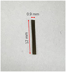
Figure 1. Basalt fiber.

Table 1. Mix proportion of BFRAAC (kg for 1 m3 of BFRAAC).
The dynamic compressive tests on BFRAAC material were carried out by split Hopkinson pressure bar (SHPB) system. As shown in Figure 2, the SHPB system includes the impact bar, incident bar, transmission bar, absorption bar, and other components. The bars are made of stainless steel and have the same diameter of 75 mm. The Ø70 × 35 mm cylindrical specimen was placed in between the incident and the transmission bars with the application of grease at specimen-bar interfaces to eliminate the friction. A copper disc as a wave shaper was attached onto the impact end of the incident bar receiving the compressive stress wave from the impact bar. Strain gauges were glued onto the surface at the mid length of the incident and transmission bars to record the incident, reflected and transmitted stress waves. A data acquisition device with frequency of 20 MHz was used to record the strain signals in voltage. An oscilloscope was adopted to monitor the waveforms in the incident and transmission bars. The strain rate in the specimens in SHPB tests can be varied by adopting different levels of pressure in the chamber.
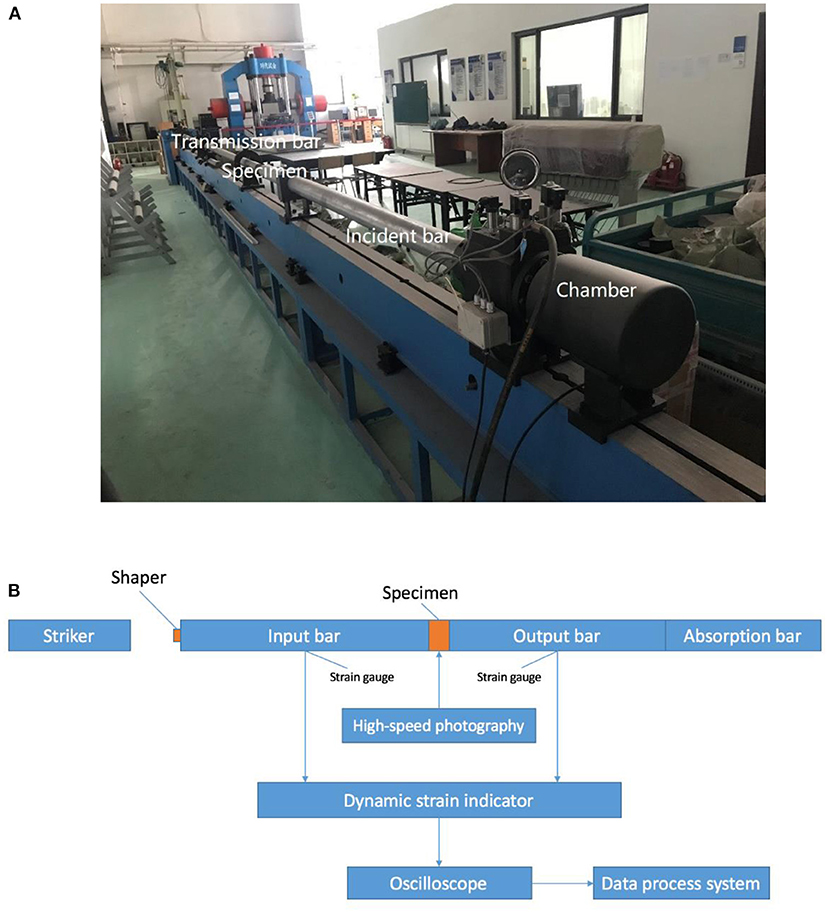
Figure 2. SHPB test system (A) photograph (B) schematic illustration.
The principle of SHPB test is based on the theory of one-dimensional stress wave propagation in elastic circular bars. This technique is one of the primary methods to study the properties of materials at high strain rates (Balendran et al., 2002). The reliability of the SHPB test results is based on the following two assumptions, namely (1) the one-dimensional stress wave propagation and (2) the stress and strain are uniformly distributed along the length of the specimen (Davies, 1948). According to the one-dimensional stress wave theory, the stress σ (t), strain rate and strain ε (t) of the specimen can be calculated by the following three formulas (Khan et al., 2018a).
where εt(t) and εr(t) are the strain histories recorded in the transmission and incident bars, respectively, E and A are the Young's modulus and cross-sectional area of the bars respectively, As and L are the cross-sectional area and length of the tested specimen, respectively, and C0 is the wave velocity in the bars.
The calculated stress and strain rate from recorded strain signals from a typical SHPB compressive test are presented in Figure 3. As shown, the value of the strain rate corresponding to the same time instant when the stress reaches its peak is determined as the strain rate of the specimen.
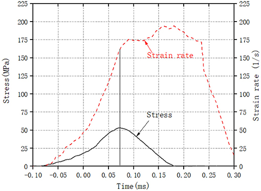
Figure 3. Typical stress and strain rate histories from SHPB test.
The failure mode of BFRAAC is shown in Figure 4. It can be seen that the addition of basalt fibers improves the brittleness of AAC material. This can be understood that when cracks were initiated and propagated in the specimen, the basalt fibers along the path of cracks were subjected to pullout load and provide additional energy consumption. Therefore, the cracked parts can be bridged by the added basalt fibers so that the structural integrity of the specimen was kept to some extent.
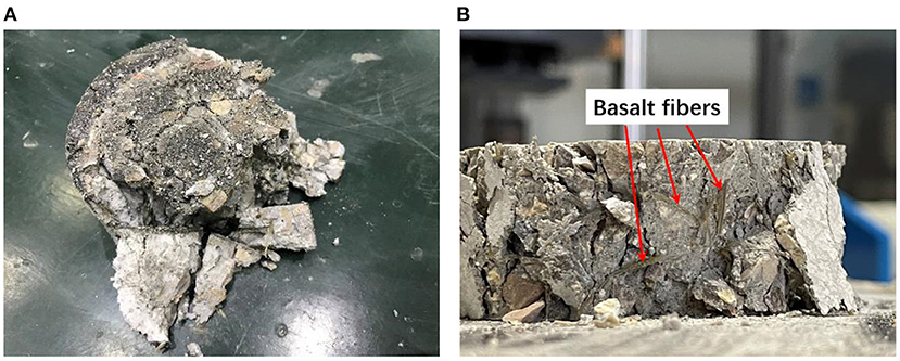
Figure 4. Illustration of the failure mode of BFRAAC under dynamic compression at strain rate of 129.67 s−1. (A) Damage and integrity of specimen after impact. (B) Fiber distribution in the matrix.
The stress-strain curves of BFRAAC specimens obtained from SHPB compression tests at different strain rates are shown in Figure 5. It can be seen from the figure that with the increase of strain rate, the compressive strength of BFRAAC generally increases, demonstrating the significant strain rate effect.
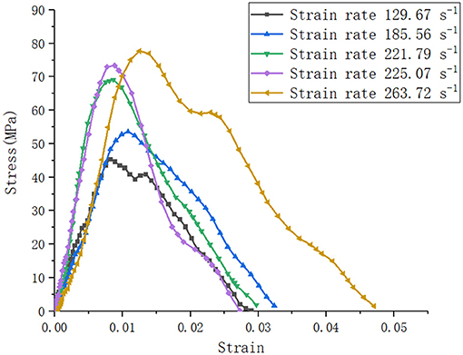
Figure 5. Typical compressive stress-strain relations of BFRAAC at different strain rates.
The dynamic increase factor (DIF, ratio of dynamic to quasi-static strength) is adopted to quantify the strain rate effect on BFRAAC compressive strengths. The relation between DIF of BFRAAC and strain rate from SHPB compression tests is given in Figure 6. The lines in the figure represent the fitted relations of the scattered data as defined by Equations 4and 5. It can be seen from the figure that the value of DIF increases with the increase of strain rate. It should be noted that due to the limitation of testing apparatus, the strain rates achieved by SHPB compressive tests cannot be lower than 100/s, which results in the gap between quasi-static and high strain rate conditions. Therefore, a linear relation is assumed in this range, following the common practices in existing studies. The maximum dynamic compressive strength of BFRAAC can be almost twice the static compressive strength. This can be understood that at relatively higher strain rate, more cracks are generated to consume the input energy in the specimen. Moreover, unlike the quasi-static tests in which the cracks mainly propagate via weak parts, i.e., interfacial transition zone between mortar matrix and aggregates, in the specimen, at high strain rate, the cracks have to propagate through coarse aggregates with higher toughness and strength than the mortar matrix, resulting in higher compressive strength of the BFRAAC specimen.
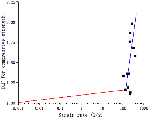
Figure 6. Compressive DIF of BFRAAC with respect to strain rate.
The dynamic splitting tensile tests on BFRAAC specimens were carried out by using INSTRON high strain rate testing system with force capacity of 100 kN. The test setup is shown in Figure 7A. The Ø70 × 35 mm specimens were diametrically placed on the loading platen so that the vertical compressive force can induce splitting tensile stress in the specimen. To avoid stress concentration and compressive failure between specimen and loading platens, wood strips were placed on the upper and lower sides of the cylindrical specimen. The thickness and width of the wood strips are 2.5 and 20 mm, respectively. It should be noted that the influence of the thickness of wood strip on quasi-static or dynamic splitting tensile test results has not been studied. It is a very interesting topic that should be addressed in future studies. The applied vertical load was recorded by the built-in sensor. The failure mode and distribution of fibers in the matrix are shown in Figure 7B. According to the theory of elasticity, the maximum horizontal tensile stress is located at the center of the cylinder. Accordingly, the splitting tensile strength σt and strain rate of the specimen can be calculated by Equations 6 and 7 (Hao et al., 2016). The strain rate obtained from impact splitting tensile tests on BFRAAC ranges from 0.15 to 2 s−1.
where P is the peak vertical load, D and B are the diameter and thickness of the cylindrical specimen, respectively, b is the width of the wood strip for the split tensile test, Es is the Young's modulus of specimen, and t0 and t1 are time instants corresponding to the initiation and peak of the stress.
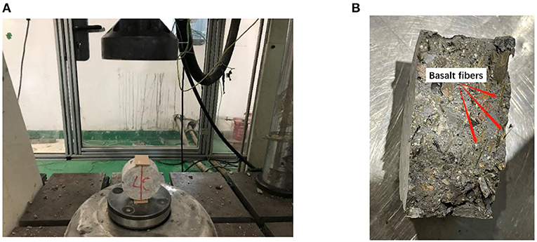
Figure 7. Illustration of dynamic splitting tensile test setup and failure mode of BFRAAC. (A) Test setup. (B) Failure mode.
The strain rate obtained from dynamic splitting tensile tests is limited to 2 s−1. To achieve higher strain rates, spall tests on Ø50 × 300 mm BFRAAC specimens were further conducted using modified SHPB test system, with removal of transmission bar, as shown in Figure 8. The rod specimen was pasted at the end of the incident bar. A copper disc was adopted as wave shaper. Apart from strain gauges at the mid length on the incident bar, additional strain gauges were attached on the surface along the length of the specimen with 50 mm intervals to record the waveform and histories. In spall test, when the impact bar hits the incident bar, a compressive stress wave is generated and propagated in the incident bar. Upon reaching the bar/specimen interface, a portion of the compressive stress wave is transmitted into the specimen and reflected as a tensile wave at the free end of the specimen. Because the tensile strength of BFRAAC is far less than its compressive strength, the tensile stress wave may cause the specimen to be fractured, namely spalled as shown in Figure 9. It should be noted that in spall tests, the incident stress wave should be well-controlled to avoid compressive damage to the specimen before the compressive stress wave is reflected as tensile wave.
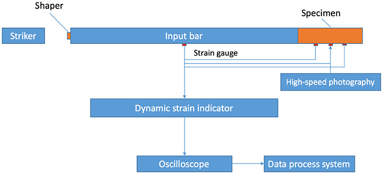
Figure 8. Plan view of the setup of spall test.
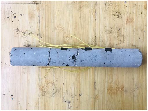
Figure 9. Illustration of the failure mode of BFRAAC in spall test at strain rate of 56.8 s−1.
In spall tests, the theory of one-dimensional stress wave propagation is used to calculate the dynamic tensile strength of BFRAAC material. The wave speed in the tested specimen can be calculated according to the different initiation time instants recorded by the series of strain gauges on the specimen and the intervals among the strain gauges. The reflected tensile stress wave is calculated according to the incident compressive stress waveform, the superposition of compressive and tensile stress waves, and the distance between the free end and the first fracture of the specimen. The dynamic tensile strength of the specimen is determined by the superimposed waveform at the first fracture location. Accordingly, the strain rate of the BFRAAC specimen in spall test is calculated by Equation 8. The strain rate obtained from spall tests on BFRAAC ranges from 10 to 94.5 s−1.
where σd is the tensile strength in spall test and t is the time for reflected tensile stress wave to propagate from free end of the specimen and the fracture location.
Based on the results from impact splitting tensile tests and spall tests, the strain rate effects on the tensile strength of BFRAAC material are illustrated in Figure 10. As can be seen, similar to compressive DIFs, the tensile DIF of BFRAAC increases with strain rate. Also due to the limitation of testing apparatus, the strain rates achieved in dynamic splitting tensile tests cannot be lower than 0.1/s. Thus, a linear relation is assumed between quasi-static and high strain rate conditions. Empirical formulas are proposed by fitting the scattered data to describe the relation between tensile strength and strain rate as given in Equations 9 and 10.
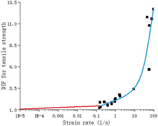
Figure 10. Tensile DIF of BFRAAC with respect to strain rate.
It is known that inertia in dynamic tests of quasi-brittle materials might influence the testing results, and its influence is dependent on the specimen size and strain rate. For the tests presented in the present study, inertia effect due to lateral confinement is of major concern, which is related to the mechanical properties of the material under triaxial stress state. With regard to the lateral inertia effect on concrete strengths in dynamic compressive tests, it is found that the contribution of lateral inertia of Ø100 mm diameter specimens to the test results is up to 15% for strain rate below 300/s (Hao et al., 2010). In the present study, the tested specimens have smaller diameter (70 vs. 100 mm in Hao et al., 2010), thus less significant influence from lateral inertia confinement. With regard to dynamic splitting tensile tests, it has been reported that the inertia effect only becomes significant when the strain rate is higher than 6/s (Hao and Hao, 2016). In this study, the maximum strain rate achieved in splitting tensile tests is only 2/s. Moreover, spall tests mainly rely on stress wave propagation in long specimen, which is fractured by reflected tensile stress wave rather than the deformation of the specimen itself. Therefore, it is reasonable to deduce that the inertia effect on the dynamic compressive strength of BFRAAC is <15% while in dynamic tensile tests the inertia effect can be ignored. Nonetheless, further study is needed to quantify the mechanical properties of BFRAAC under triaxial loading to identify the sensitivity of material strength to confining pressure, based on which the evaluation of the influence of lateral inertia confinement in dynamic compressive tests can be conducted.
The dynamic compressive and tensile strengths of basalt fiber reinforced alkali-activated concrete (BFRAAC) material are experimentally investigated in the present study. Tests adopting split Hopkinson pressure bar (SHPB) system, INSTRON high strain rate system and modified SHPB system were carried out to determine the compressive and tensile strengths at high strain rates. It is found that the strengths of BFRAAC material are significantly enhanced with the increase of strain rate. Through the series of tests, the strain rate effects on compressive and tensile strengths of BFRAAC material are analyzed. Empirical relations of the dynamic increase factor and strain rate are proposed based on test data to formulate the strain rate effect. The proposed relations can be used in design and analysis of BFRAAC structures subjected to blast and impact loadings.
The original contributions presented in the study are included in the article/supplementary material, further inquiries can be directed to the corresponding authors.
CL: methodology, validation, formal analysis, investigation, data curation, and writing-original draft. YW: methodology and validation. SL: methodology, investigation, writing-review, and editing. YH: conceptualization, methodology, writing-review, editing, supervision, project administration, and funding acquisition. All authors contributed to the article and approved the submitted version.
The authors would like to acknowledge financial supports from Shock and Vibration of Engineering Materials and Structures Key Laboratory of Sichuan Province, National Natural Science Foundation of China (grant number: 51778415), Natural Science Foundation of Tianjin (grant number: 17JCYBJC42600), Natural Science Foundation of Hebei Province (E2020402079), and National Key Research and Development Program of China (grant number: 2019YFC1907202) for carrying out this study.
The authors declare that the research was conducted in the absence of any commercial or financial relationships that could be construed as a potential conflict of interest.
Ana, M., Fernandez-Jimenez, A. P., and Cecilio, L. H. (2006). Engineering properties of alkaliactivated fly ash concrete. ACI Mater. J. 103, 106–112. doi: 10.14359/15261
Balendran, R. V., Zhou, F. P., Nadeem, A., and Leung, A. Y. T. (2002). Influence of steel fibres on trength and ductility of normal and lightweight high strength concrete. Build. Environ. 37, 1361–1367. doi: 10.1016/S0360-1323(01)00109-3
Benhalal, E., Zahedi, G., Shamsaei, E., and Bahodori, A. (2012). Global strategies and potentials to curb CO2 emissions in cement industry. J. Clean. Prod. 51, 142–161. doi: 10.1016/j.jclepro.2012.10.049
Davies, R. M. (1948). A critical study of the Hopkinson pressure bar. Philos. Trans. R. Soc. London Ser. A Math. Phys. Sci. 240, 375–457. doi: 10.1098/rsta.1948.0001
Deb, P. S., Nath, P., and Sarker, P. K. (2014). The effects of ground granulated blast-furnace slag blending with fly ash and activator content on the workability and strength properties of geopolymer concrete cured at ambient temperature. Mater. Design 62, 32–39. doi: 10.1016/j.matdes.2014.05.001
Feng, K. N., Ruan, D., Pan, Z., Collins, F., Bai, Y., Wang, C. M., et al. (2014). Effect of strain rate on splitting tensile strength of geopolymer concrete. Mag. Concr. Res. 66, 825–835. doi: 10.1680/macr.13.00322
Fernandez-Jimenez, A., García-Lodeiro, I., and Palomo, A. (2007). Durability of alkaliactivated fly ash cementitious materials. J. Mater. Sci. 42, 3055–3065. doi: 10.1007/s10853-006-0584-8
Ganesan, N., Abraham, R., Deepa Raj, S., and Sasi, D. (2014). Stress–strain behaviour of confined Geopolymer concrete. Constr. Buil. Materi. 73, 326–331. doi: 10.1016/j.conbuildmat.2014.09.092
García-Lodeiro, I., Palomo, A., and Fernández-Jiménez, A. (2007). Alkali–aggregate reaction in activated fly ash systems. Cem. Concr. Res. 37, 175–183. doi: 10.1016/j.cemconres.2006.11.002
Geiseler, J., Kollo, H., and Lang, E. (1995). Influence of blast-furnace cements on durability of concrete structures. ACI Mater. J. 92, 252–257. doi: 10.14359/9773
Haider, G. M., Sanjayan, J. G., and Ranjith, P. G. (2014). Complete triaxial stress–strain curves for geopolymer. Constr. Build. Mater. 69, 196–202. doi: 10.1016/j.conbuildmat.2014.07.058
Hao, Y., and Hao, H. (2016). Finite element modelling of mesoscale concrete material in dynamic splitting test. Adv. Struct. Eng. 19, 1027–1039. doi: 10.1177/1369433216630828
Hao, Y., Hao, H., and Chen, G. (2016). Experimental investigation of the behavior of spiral steel fibre reinforced concrete beams subjected to drop-weight impact loads. Mater. Struct. 49, 353–370. doi: 10.1617/s11527-014-0502-5
Hao, Y., Hao, H., and Li, Z. X. (2010). Numerical analysis of lateral inertial confinement effects on impact tests of concrete compressive material properties. Int. J. Prot. Struct. 1, 145–167. doi: 10.1260/2041-4196.1.1.145
Khan, M. Z. N., Hao, Y., Hao, H., and Shaikh, F. U. A. (2018b). Mechanical properties of ambient cured high strength hybrid steel and synthetic fibers reinforced geopolymer composites. Cem. Concr. Compos. 85, 133–152. doi: 10.1016/j.cemconcomp.2017.10.011
Khan, M. Z. N., Hao, Y., Hao, H., and Shaikh, F. U. A. (2018a). Experimental evaluation of quasi-static and dynamic compressive properties of ambient-cured high-strength plain and fiber reinforced geopolymer composites. Constr. Build. Mater. 166, 482–499. doi: 10.1016/j.conbuildmat.2018.01.166
Khandelwal, M., Ranjith, P. G., Pan, Z., and Sanjayan, J. G. (2013). Effect of strain rate on strength properties of low-calcium fly-ash-based geopolymer mortar under dry condition. Arab. J. Geosci. 6, 2383–2389. doi: 10.1007/s12517-011-0507-0
Li, W., and Xu, J. (2009). Mechanical properties of basalt fiber reinforced geopolymeric concrete under impact loading. Mater. Sci. Eng. 505, 178–186. doi: 10.1016/j.msea.2008.11.063
Liu, S., Hao, Y., and Ma, G. (2021). Approaches to enhance the carbonation resistance of fly ash and slag based alkali-activated mortar-experimental evaluations. J. Clea. Prod. 280:124321. doi: 10.1016/j.jclepro.2020.124321
Luga, E. (2015). Properties of fly ash and blast furnace slag geopolymer mortars (Ph.D. thesis). Institute of Science, Erciyes University, Kayseri, Turkey.
Luo, X., and Xu, J. (2013). Dynamic splitting-tensile testing of highly fluidised geopolymer concrete. Mag. Concr. Res. 65, 837–843. doi: 10.1680/macr.12.00172
Menna, C., Asprone, D., Forni, D., Roviello, G., Ricciotti, L., Ferone, C., et al. (2015). Tensile behaviour of geopolymer-based materials under medium and high strain rates. EPJ Web Conf. EDP Sci. 01034, 1–4. doi: 10.1051/epjconf/20159401034
Noushini, A., Aslani, F., Castel, A., Gilbert, R. I., Uy, B., and Foster, S. (2016). Compressive stress-strain model for low-calcium fly ash-based geopolymer and heat-cured Portland cement concrete. Cem. Concr. Compos. 73, 136–146. doi: 10.1016/j.cemconcomp.2016.07.004
Ohno, M., and Li, V. C. (2014). A feasibility study of strain hardening fiber reinforced fly ash-based geopolymer composites. Constr. Build. Mater. 57, 163–168. doi: 10.1016/j.conbuildmat.2014.02.005
Punurai, W., Kroehong, W., Saptamongkol, A., and Chindaprasirt, P. (2018). Mechanical properties, microstructure, and drying shrinkage of hybrid fly ash-basalt fiber geopolymer paste. Constr. Build. Mater. 186, 62–70. doi: 10.1016/j.conbuildmat.2018.07.115
Shaikh, F. U. A., and Supit, S. W. M. (2014). Mechanical and durability properties of high volume fly ash (HVFA) concrete containing calcium carbonate (CaCO3) nanoparticles. Constr. Build. Mater. 70, 309–321. doi: 10.1016/j.conbuildmat.2014.07.099
Sim, J., and Park, C. (2005). Characteristics of basalt fiber as a strengthening material for concrete structures. Compos. Part B Eng. 36, 504–512. doi: 10.1016/j.compositesb.2005.02.002
Tran, T. T., Pham, T. M., and Hao, H. (2019). Rectangular stress-block parameters for fly-ash and slag based geopolymer concrete. Structures 19, 143–155. doi: 10.1016/j.istruc.2019.01.006
Keywords: alkali-activated concrete, basalt fiber, dynamic compression, dynamic tension, high strain rate
Citation: Lian C, Wang Y, Liu S and Hao Y (2021) Experimental Study of the Dynamic Compressive and Tensile Strengths of Fly Ash and Slag Based Alkali-Activated Concrete Reinforced With Basalt Fibers. Front. Mater. 8:651581. doi: 10.3389/fmats.2021.651581
Received: 10 January 2021; Accepted: 23 February 2021;
Published: 18 March 2021.
Edited by:
Faiz Uddin Ahmed Shaikh, Curtin University, AustraliaReviewed by:
Genwei Wang, Taiyuan University of Technology, ChinaCopyright © 2021 Lian, Wang, Liu and Hao. This is an open-access article distributed under the terms of the Creative Commons Attribution License (CC BY). The use, distribution or reproduction in other forums is permitted, provided the original author(s) and the copyright owner(s) are credited and that the original publication in this journal is cited, in accordance with accepted academic practice. No use, distribution or reproduction is permitted which does not comply with these terms.
*Correspondence: Shan Liu, c2hhbl9saXVAdGp1LmVkdS5jbg==; Yifei Hao, aGFvLnlpZmVpQHRqdS5lZHUuY24=
Disclaimer: All claims expressed in this article are solely those of the authors and do not necessarily represent those of their affiliated organizations, or those of the publisher, the editors and the reviewers. Any product that may be evaluated in this article or claim that may be made by its manufacturer is not guaranteed or endorsed by the publisher.
Research integrity at Frontiers
Learn more about the work of our research integrity team to safeguard the quality of each article we publish.