 Ma Guanbing
 Ding Hui1*
 Zhu Chuanyu
94% of researchers rate our articles as excellent or good
Learn more about the work of our research integrity team to safeguard the quality of each article we publish.
Find out more
ORIGINAL RESEARCH article
Front. Mater., 08 March 2021
Sec. Smart Materials
Volume 8 - 2021 | https://doi.org/10.3389/fmats.2021.643703
This article is part of the Research TopicNew Piezoelectric Materials and Devices: Fabrication, Structures, and ApplicationsView all 11 articles
A compact five-element integrated ultrasonic transducer was designed and manufactured for the inspection of defects in the split pins of control rod guide tubes in nuclear power plants. The transducer consists of three types of ultrasonic elements to detect cracks in the entire volume of the split pins. In the transducer design, two main factors were investigated: the coupling of elements in confined space and measurement sensitivity. The experimental results demonstrated that the developed transducer has good acoustic performance and defect response capabilities and can detect 10 mm × 2 mm × 0.5 mm notches in the three areas of the split pins. This work provides a foundation for applications in nuclear site inspections.
Ultrasonic testing (UT) (Shung, 2011) has become indispensable in nuclear power plants for regular health status monitoring of in-service equipment because of its ability to locate minor defects in materials and structures non-destructively without detrimental environmental effects. To improve the efficiency and safety of nuclear power generation, components with complex geometries and special materials are used in next-generation nuclear power units. Ultrasonic testing of these complex structures places high requirements on ultrasonic transducers. Meanwhile, the development of a high-efficiency transducer is always important for reducing the radiation dose to which the ultrasonic testing operator is exposed (Xia and Han, 2016; Yuan et al., 2011; Guo et al., 2012). In recent years, many researchers have focused on the development of ultrasonic array probes and ultrasonic phased array technology to improve the efficiency of ultrasonic detection for key components in nuclear power plants (Norris et al., 1999; Chikazawa and Yoshiuji, 2015; Trampus, 2014; Drinkwater and Wilcox, 2006; Kim et al., 2016a; Shi et al., 2014; Fu et al., 2019). Trampus (Trampus, 2019) adopted a smart phase array UT probe to detect radial fatigue cracks in a nozzle radius. Yamamoto et al. (Yamamoto et al., 2016) developed a phased array ultrasonic inspection technique for monitoring cast austenitic stainless steel parts in nuclear power plants. Fu et al. (Fu et al., 2019) designed a 2.5 MHz 64 el dual-element matrix array probe and a 2.25 MHz 64 el single-linear array probe for the inspection of vertical defects in the butt-joint welds of CFETR vacuum vessel port stubs.
However, the ultrasonic phased array probes are too large to reach the surfaces of the components in complex structures with narrow scanning spaces. Even if the transducer could reach these components, the ultrasonic beams could not cover the target inspection area because of the limited scanning space. Compact ultrasonic probes have emerged as a solution to this problem (Yoon et al., 2014; Erhard et al., 2001; Song et al., 2002; Kim et al., 2016b; Abdallah and Namgung 2018). Pajnić et al. (Pajnić et al., 2009) developed a slim sword-like trinary probe with a pair of time-of-flight diffraction (TOFD) transducers for the detection and sizing of circumferential and axial cracks in the 3 mm gap between the inner surface of the penetration nozzle and the thermal sleeve. Glass et al. (Glass et al., 2011) proposed a 4-element probe to detect cracks inside nuclear reactors.
In this study, a compact multi-element ultrasonic transducer was designed and fabricated for the inspection of split pins, which are the key connecting parts of the internal components in the reactor core of a nuclear power plant. The spectrum performance and defect detection ability of the ultrasonic transducer were quantified. A mockup of the interior of a reactor core containing the split pins was designed and produced to simulate the actual engineering inspection environment. An underwater robot was developed to carry the transducer for underwater testing.
A split pin is the key component for connecting and ensuring the accurate positioning of the control rod guide tube and the upper grid plate (IAEA, 2007; Andresen et al., 2012), as shown in Figure 1A. Nuts are used to fasten the split pins to the control rod guide tubes, as shown in Figure 1B. The material of the split pin is the alloy Inconel X-750. Solid solution and surface shot peening treatments were performed on the pin during the manufacturing process. The structure of the split pin is shown in Figure 1C. The total length of the split pin is 92.95 mm, and the free state diameter of the open end is 21.3 mm. Its diameter after compression is 20.5 mm. The width of the middle open slot is only 3.2 mm, and its length is 30 mm.
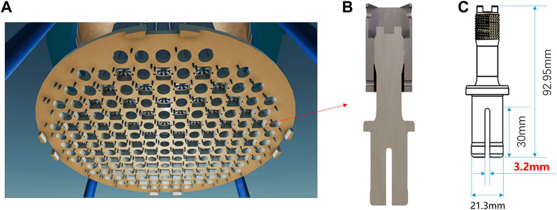
FIGURE 1. Structure of the split pin: (A) postion of the split pin; (B) cross section; (C) geometry.
The structure of the split pin can be divided into the leaf zone, transition zone, shrank zone, and thread zone, as shown in Figure 2. Part failures mainly occur in the root of the open leaf area, the transition area between the shrank and leaf zones, and the first buckled area in the thread zone at three positions. The most common type of failure is cracks. The orientation of the cracks occurring in the thread and leaf zones is perpendicular to the axis of the split pin, while in the transition zone it is in the range of 30–60° along the axial direction.

FIGURE 2. Ultrasonic inspection strategies: (A) 0° L for leaf zone; (B) 0° L for thread zone; (C) 45° S for transition zone; (D) combined design.
Three types of conventional ultrasonic transducers are needed for the inspection of cracks in the three zones mentioned above. For cracks in the leaf zone, two semi-circular elements utilizing a 0° longitudinal wave are aligned along the bottom plane of the split pin, as shown in Figure 2A. For cracks in the threaded zone, a long strip element utilizing a 0° longitudinal wave is aligned on the top of the middle open slot, and the two semi-circular elements choosing emit-receive mode are also been used, as shown in Figure 2B. For tilt cracks in the transition zone, a send-and-receive mode transducer with two tandem elements are aligned on the side of the open slot in the leaf area, as shown in Figure 2C. A 45° transverse wave is used to detect the tilt cracks. It is time-consuming to use conventional ultrasonic transducers because changing the transducer takes place in cumbersome steps during the automatic scanning. To improve inspection efficiency, a compact five-element plug-in integrated transducer was designed to detect cracks in the entire volume of the split pins, as shown in Figure 2D.
The design details are as follows:
(1) Element frequency and size design: The split pin is made of a nickel-based material, which has higher acoustic attenuation compared to carbon steel. Therefore, a low-frequency wave should be chosen for inspecting the high-attenuation material. However, the length of the split pin is only 92.95 mm. The element frequency was set to 5 MHz in consideration of the tradeoff between the resolution and sensitivity. The elements were designed to be as large as possible to provide maximum detection coverage. Elements E4 and E5 were designed as semi-circles with a diameter of 16 mm. Elements E2 and E3 were designed as rectangles with a size of 2.4 mm × 8 mm. The size of element E1 is 2.2 mm × 8 mm. The design of element frequency and size is validated by CIVA, a professional sound field simulation software. The results show that the selected frequency and size can effectively cover the area need to be detected in the maximum sound pressure-6dB range, as shown in Figure 3. Other frequencies such as 3, 4, and 6 MHz are also simulated. The sound field distribution simulation in the leaf zone of E4 or E5 in the split pin was shown in Figure 4. taking the leaf zone for example. The calculation results show that 5 MHz is a suitable frequency.
(2) Angle design: The defects in the thread and leaf area occur mainly in the direction perpendicular to the axis of the split pin. Therefore, the E4, E5, and E1 elements utilize a 0° longitudinal wave to detect defects at the leaf zone and the thread zone. The E2 and E3 elements were designed to utilize a transverse wave mode with a refraction angle of 45° to detect defects with axial directions of 30–60° at the transition zone. The distance between the E2 and E3 elements was designed to be 15 mm. The reason for this design is: The beam path of the 45° elements can detect transition zone 30–60° defects approximately vertically, through the split pin side-wall reflection, and the tandem detection pattern can be used for adapting to the change of the angle of the defect, therefore, it has a high probability of detection (POD).
(3) Coupling matching design: The inspection of the split pin was performed in an underwater environment. Water can, therefore, be used as the ultrasonic testing couplant. To ensure full coupling of the element, the size of the inserted chip was designed to meet strict requirements. The length of the inserted chip was accurately designed to be 30 mm to ensure full contact between the elements E4, E5, and E1. For the transition zone inspection, the element needs to be inserted into the opening slot, which has a width of 2.4 mm. Therefore, the thickness of the designed insert was made to be 2.2 mm, and a compressible spring was incorporated into the design on one side of the insert. The compressible spring fitting method was adopted to ensure the quality of the coupling and improve the safety performance of the transducer.
(4) Transducer housing design: The length of the transducer housing is same as the thickness of the upper grid plate, which is 45 mm. Four bolt holes were incorporated into the design to fix the transducer.

FIGURE 3. Sound field coverage simulation: (A) E4/E5 for leaf zone; (B) E4/E5 for thread zone; (C) E1 for thread zone; (D) E2/E3 for transition zone.
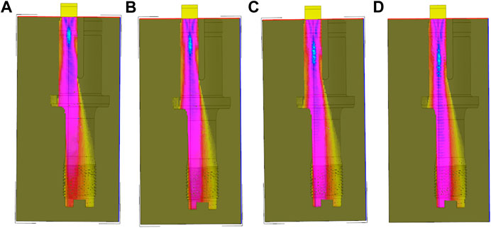
FIGURE 4. Sound field distribution simulation of E4 or E5: (A) 3 MHz; (B) 4 MHz; (C) 5 MHz; (D) 6 MHz.
The ultrasonic transducer element, damping, cable, and connector were selected based on the design of the ultrasonic transducer, and the housing of the transducer was fabricated. The split pin ultrasonic integrated transducer was then assembled. The process is shown in Figure 5.
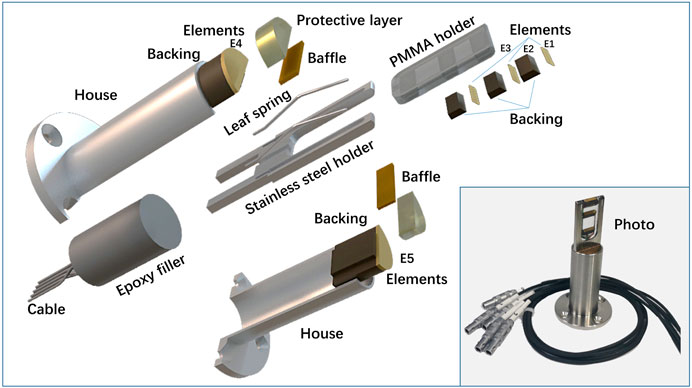
FIGURE 5. Exploded device structure of the ultrasonic transducer.
The piezoelectric ceramic PZT (1–3 composite, Changzhou ultrasonic electronics Co., LTD) was chosen for the transducer element considering the vibration characteristics. The protective film was made of polymethyl methacrylate (PMMA), which has good sound permeability, wear resistance, chemical stability, and radiation resistance. The PMMA thickness of the E4 and E5 is 5 mm E1 protective layer adopts a semi-circular structure adapted to the bottom arc end of the split pin, and the maximum thickness of PMMA, is the radius of the arc 1.6 mm E2 and E3 protective layer thickness design is mainly considered its 45° refractive angle in the split pin. According to Snell's law of refraction, the E2 and E3 in PMMA has a tilt of 38.5°, therefore, the thickness of the protective layer is 1–2.4 mm.
The transducer damping stops the vibration of the piezoelectric element quickly, reduces the pulse width, improves the resolution, and absorbs the ultrasonic waves emitted from the back of the element to reduce the initial pulse noise. The damping is made of a 35% tungsten powder +65% epoxy resin composite material.
A RG178 cable is used as the transducer cable partly because of its flexibility and resistance to electromagnetic interference, moisture, and temperature extremes. The length of the cables is 2.2 m. The connector uses a 50 Ω LEMO 00 coaxial connector. SUS304 stainless steel is used for the transducer housing owing to its ease of decontamination in a radioactive environment. The processing accuracy was precisely controlled, and the sharp edges were blunted during shell processing to prevent the edges from damaging the inspected component.
The overall assembly process of the probe is as follows: E1, E2, and E3 were first fixed on the PMMA holder. The whole assembly was then installed on the stainless steel holder together with the leaf spring. The probe wires of E1, E2, and E3 were placed through the stainless steel holder slot. The protective layer, baffle, E4, and backing were then installed into the housing, which was then filled with an epoxy filler. The 2.2 m long cable of the five elements was then connected to the BNC-type LEMO 00 cable.
The electrical impedance characteristics were measured using an impedance analyzer (Agilent 4294A). The center frequency and bandwidth (BW) of the transducers were characterized using a pulse-echo response arrangement and two self-designed blocks. The material of the test blocks was X750, which is the same as that of the split pins. Test block 1 was a semi-cylindrical block with a diameter of 10 mm and a height of 22 mm. Test block 2 was a cylindrical block with an opening width of 3.2 mm, diameter of 21.3 mm, and length of 73 mm. Test block 1 was mainly used to evaluate the performance of E2 and E3, and test block 2 was mainly used to evaluate the performance of E1, E4, and E5. The experimental setups are shown in Figure 6.
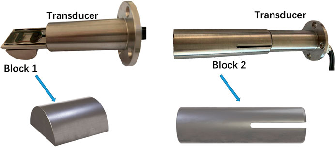
FIGURE 6. Transducer testing using the designed blocks.
Three types of defects were introduced to evaluate the detection performance of the ultrasonic transducer. The defects were made by wire-electrode cutting and were located at the leaf zone, transition zone, and thread zone of the split pin. The depth of the three defects was 2 mm and the outer arc length was 10 mm. The gap of the defect is 0.2 mm. The distribution of the defects is shown in Figure 7.
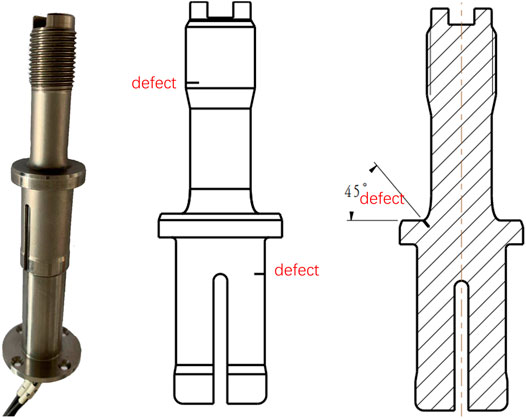
FIGURE 7. Transducer testing using the blocks with defects.
The measured impedance of the compact transducer is shown in Figure 8. All five elements had a nominal frequency of 5 MHz when the impedance was 50 Ω. The time domain and frequency domain pulse echoes are shown in Figure 9. The ultrasonic transducer was excited by an ultrasonic pulser and receiver (DPR300) with a pulse energy of 170 μJ and a repetition rate of 200 Hz. An acquisition card (NI PXIe-5260) was used for data acquisition at a sampling frequency of 1.25 GHz. A fast Fourier transform (FFT) was used to obtain the frequency spectrum of the pulse-echo signal. The central frequencies of the five elements are all located between 4 and 4.5 MHz. The two semicircular elements (E4 and E5) have similar wave forms, and the peak-to-peak amplitude is approximately 110 dB, which is the highest among the five elements. This is because the elements E4 and E5 are larger than the other. The amplitude of the signals received from elements E2 and E3 is approximately 50 dB, which is much lower than that from the other elements. This is because the two elements were used to emit shear waves. Acoustic attenuation occurred during the mode conversion at the interface between the PMMA wedge and the specimen when the ultrasound wave propagated into the wedge.

FIGURE 8. Impedance and phase spectra of ultrasonic transducer: (A) element 1; (B) element 2; (C) element 3; (D) element 4; and (E) element 5.
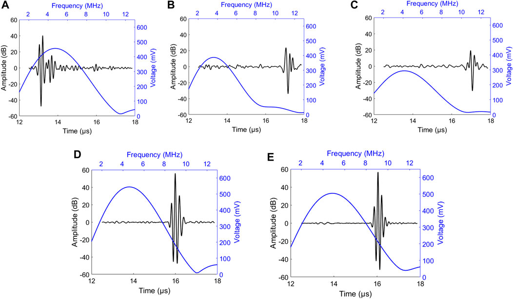
FIGURE 9. Pulse-echo waveforms and frequency spectra of the transducer: (A) element 1; (B) element 2; (C) element 3; (D) element 4; (E) element 5.
The detection performance of the probe was tested with split pins containing defects. The results show that the defects in the three zones could be accurately detected. The defect 3 in the leaf zone could be detected clearly, as shown in Figure 10A. The strong echo signal after the notch signal was caused by the reflected signal in the variable diameter area of the split pin transition zone. The notch signal in the threaded area could also be clearly detected by E1. The two signals with higher amplitudes seen after the notch signal are the reflected signals formed by the bottom surface of the split pin and the steps on the bottom surface. These two signals can be used as structure signals to characterize the performance of the transducer, as shown in Figure 10B. For the detection of defects in the transition zone, elements E2 and E3 were used for tandem ultrasonic inspection. When a defect is encountered, the incident wave is reflected and received by the receiving probe, and there is a defect echo displayed at a fixed sound path position. This is because the ultrasonic propagation sound path between the transmitting element and the receiving element is fixed. The sound path can be calculated by S = 2T/cos β, where T is the thickness of the split pin leaf, and β is the refraction angle of the probe. As the thickness of the split pin leaf was T = 8.7 mm, and the refraction angle was β = 45°, the defect sound path was calculated to be approximately 24.5 mm, which is consistent with the notch signal shown in Figure 10C. In summary, the test results on the split pins with defects show that the compact multi-element ultrasonic transducer could detect all the designed defects in different zones.
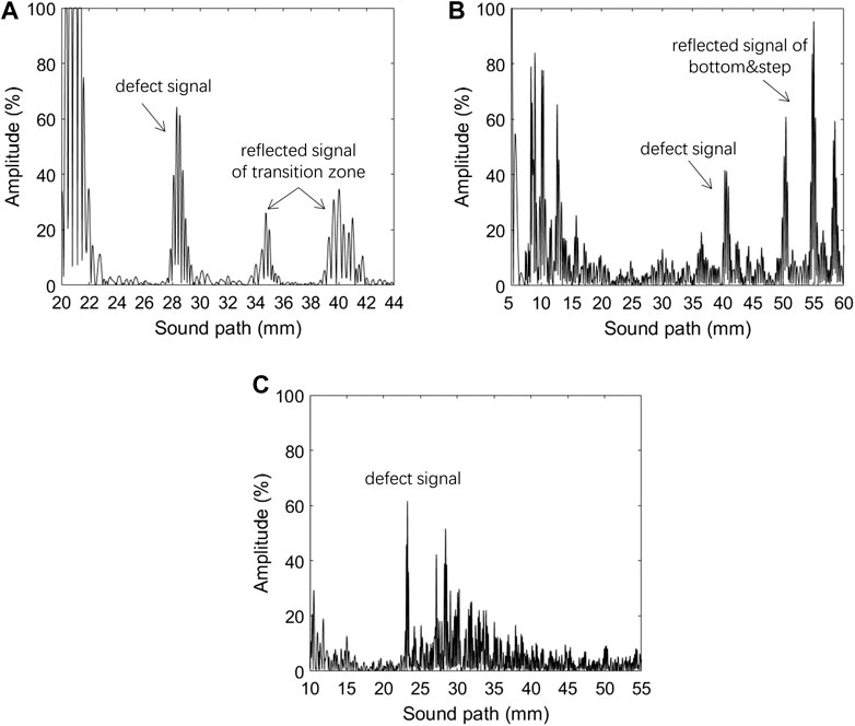
FIGURE 10. Defect detection capability of transducer. (A) leaf zone; (B) thread zone; (C) transition zone.
To assess the robustness of the compact transducer for field applications, a mockup of the interior of the upper reactor containing the control rod guide tube split pins was designed and fabricated. An underwater robot was also developed to carry the compact multi-element ultrasonic transducer to the target inspection area. The test was performed in a water-filled pool, as shown in Figure 11. The compact transducer could perform inspection tasks underwater for seven days without interruption. There are 32 split pins fixed on the mockup, of which 16 split pins have 50 crack defects in sensitive areas, and all defects can be detected using the developed compact multi-element ultrasonic transducer. This ability to work for long durations is highly advantageous for the inspection of control rod guide tube split pins in third-generation advanced pressurized water reactor (PWR) nuclear power plants in the future.
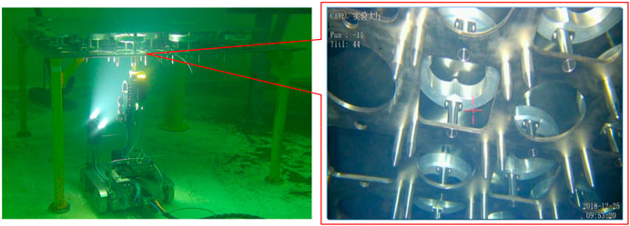
FIGURE 11. Robot with transducer for underwater inspection.
A compact five-element compact ultrasonic transducer was designed and produced for the inspection of split pins in control rod guide tubes in nuclear power plants. The experimental results show that the central frequencies of all five elements were controlled to be approximately 4–4.5 MHz. The compact transducer can detect all the defects in the various zones of the split pin with a defect length and height sensitivity of 10 mm length and 2 mm, respectively. The compact transducer has been proven to be capable of sustained operation in an underwater environment for seven days. This capability lays the foundation for further implementation and applications in nuclear power plants.
The raw data supporting the conclusions of this article will be made available by the authors, without undue reservation.
MG: transducer design DH: funding receiver WW: block design MC: impedance analysis YJ: pulse echo analysis ZC: under water testing. TJ: sound field simulation.
The study was supported by the National Key Research and Development Program of China (no. 2018YFB1106100).
Authors MG, WW, MC, ZC, and TJ were employed by company CGN Inspection Technology Co., Ltd.
The remaining authors declare that the research was conducted in the absence of any commercial or financial relationships that could be construed as a potential conflict of interest.
Abdallah, K. A. A., and Namgung, I. (2018). Virtual reality development and simulation of BMI nozzle inspection system for use during regular refueling outage of APR1400 family of reactors. Ann. Nucl. Energ. 116, 235–256. doi:10.1016/j.anucene.2017.12.010
Andresen, P. L., Flores-Preciado, J., Martin, M. M., and Robert, C. (2012). “Microstructure and SCC of alloy X-750,” in 15th international conference on environmental degradation of materials in nuclear power systems water reactors, Salt Lake City, Utah, April 2, 2012 (Wiley), 719–740.
Chikazawa, Y., and Yoshiuji, T. (2015). Water experiment on phased array acoustic leak detectionsystem for sodium-heated steam generator. Nucl. Eng. Des. 289, 1–7. doi:10.1016/j.nucengdes.2015.04.008
Drinkwater, B. W., and Wilcox, P. D. (2006). Ultrasonic arrays for non-destructive evaluation: a review. NDT E Int. 39, 525–541. doi:10.1016/j.ndteint.2006.03.006
Erhard, A., Schenk, G., Hauser, T., and VÖlz, U. (2001). New applications using phased array techniques. Nucl. Eng. Des. 206, 325–336. doi:10.1016/S0029-5493(00)00419-2
Fu, Y., Wu, J., Liu, Z., Wang, R., Jiang, B., and Wen, W. (2019). Phased array ultrasonic test of vertical defect on butt-joint weld of CFETR vacuum vessel port stub. Fusion Eng. Des. 141, 1–8. doi:10.1016/j.fusengdes.2019.02.010
Glass, S. W., Thigpen, B., and Renshaw, J. (2011). “Ultrasound and nonlinear resonant testing of nuclear reactor internals bolts,” in Proceedings of the ASME 2011 pressure vessels and piping conference, Baltimore, Maryland, July 17–21, 2011 (Baltimore, MD: ASME), 185–189.
Guo, Y., Yuan, Q., Sun, Z., Logan, K., and Lam, C. (2012). Development of ultrasonic phased array systems for applications in tube and pipe inspection. AIP Conf. Proc. 1430, 1897. doi:10.1063/1.4716442
IAEA (2007). Assessment and management of ageing of major nuclear power plant componets important to safety: PWR vessel internals. Vienna, Austria: International Atomic Energy Agency, 74.
Kim, G. H., Park, C. K., Jin, S. W., Kim, H. S., Hong, K. H., Lee, Y. J., et al. (2016a). Qualification of phased array ultrasonic examination on T-joint weld of austenitic stainless steel for ITER vacuum vessel. Fusion Eng. Des. 109 (111), 1099–1103. doi:10.1016/j.fusengdes.2016.01.015
Kim, H.-H., Kim, H.-J., Song, S.-J., Kim, K.-C., and Kim, Y.-B. (2016b). Simulation based investigation of focusing phased array ultrasound in dissimilar metal welds. Nucl. Eng. Technol. 48, 228–235. doi:10.1016/j.net.2015.10.011
Norris, W. E., Naus, D. J., and Graves, H. L. (1999). Inspection of nuclear power plant containment structures. Nucl. Eng. Des. 192, 303–329. doi:10.1016/S0029-5493(99)00125-9
Pajnić, M., Franjić, H., Gabrijel, S, and Jarnjak, F. (2009). “Advanced approach of reactor pressure vessel head inspection and repair/removal of RPVH J-weld indications,” in Proceedings of the international conference nuclear energy for new Europe, Bled, Slovenia, September 14–17, 2009 (Dubrovnik, Croatian: Croatian Nuclear Society), 112.
Yamamoto, S., Semboshi, J., Sugawara, A., and Ochiai, M. (2016). “Phased array ultrasonic inspection technique for cast austenitic stainless steel parts of nuclear power plants,” in 2016 24th international conference on nuclear engineering, Charlotte, North Carolina, June 26–30, 2016 (ASME), 6.
Shi, J., Hou, D., Guo, W., Zhou, Y., Chen, X., and Zheng, J. (2014). “Ultrasonic inspection of large diameter polyethylene pipe used in nuclear power plant,” in American society of mechnical Engineering, vessels and piping division, Anaheim, California, July 20–24, 2014 (ASME), 8.
Shung, K. K. (2011). Diagnostic ultrasound: past, present, and future. J. Med. Biol. Eng. 3, 1371–1374. doi:10.5405/jmbe.871
Song, S.-J., Shin, H. J., and Jang, Y. H. (2002). Development of an ultrasonic phased array system for nondestructive tests of nuclear power plant components. Nucl. Eng. Des. 214, 151–161. doi:10.1016/S0029-5493(02)00024-9
Trampus, P. (2014). Ensuring safety of structures and components at nuclear power Plants,1st international conference on structural integrity, ICONS-2014. Procedia Eng. 86, 486–495. doi:10.1016/j.proeng.2014.11.062
Trampus, P. (2019). Role and importance of NDE in nuclear power plant life extension. Procedia Struct. Integr. 16, 161–168. doi:10.1016/j.prostr.2019.07.036
Xia, J. W., and Han, C. (2016). Ultrasound inspection of zirconium alloy cladding tube for nuclear fuel. Nucl. Power Eng. 3, 122–126. doi:10.13832/j.jnpe.2016.03.0122
Yoon, B., Kim, Y., and Lee, J. (2014). Steam generator small bore piping socket weld inspection using the phased array ultrasonic technique. J. Nucl. Sci. Technol. 51 (2), 231–239. doi:10.1080/00223131.2014.855151
Keywords: ultrasonic transducer, pins inspection, nuclear application, defect detection, underwater testing
Citation: Guanbing M, Hui D, Weiqiang W, Chao M, Jingli Y, Chuanyu Z and Jianbang T (2021) Compact Multi-Element Ultrasonic Transducer for Inspecting Split Pins in Nuclear Power Plants. Front. Mater. 8:643703. doi: 10.3389/fmats.2021.643703
Received: 18 December 2020; Accepted: 01 February 2021;
Published: 08 March 2021.
Edited by:
Chunlong Fei, Xidian University, ChinaReviewed by:
Kwok Ho Lam, Hong Kong Polytechnic University, Hong KongCopyright © 2021 Guanbing, Hui, Weiqiang, Chao, Jingli, Chuanyu and Jianbang. This is an open-access article distributed under the terms of the Creative Commons Attribution License (CC BY). The use, distribution or reproduction in other forums is permitted, provided the original author(s) and the copyright owner(s) are credited and that the original publication in this journal is cited, in accordance with accepted academic practice. No use, distribution or reproduction is permitted which does not comply with these terms.
*Correspondence: Ma Guanbing, bWFndWFuYmluZ0BjZ25wYy5jb20uY24=; Ding Hui, ZGluZ2h1aUBzZXUuZWR1LmNu
Disclaimer: All claims expressed in this article are solely those of the authors and do not necessarily represent those of their affiliated organizations, or those of the publisher, the editors and the reviewers. Any product that may be evaluated in this article or claim that may be made by its manufacturer is not guaranteed or endorsed by the publisher.
Research integrity at Frontiers
Learn more about the work of our research integrity team to safeguard the quality of each article we publish.