 Guo-Jun Yu
 Shao-Jie Zhu1
 Cheng-Bin Du
- 1Faculty of Civil Engineering and Mechanics, Jiangsu University, Zhenjiang, China
- 2Department of Engineering Mechanics, Hohai University, Nanjing, China
In order to control the vibration of civil building structures, a magnetic rate-controlled stage damper (MRCSD) is designed based on a magnetorheological shear thickening fluid (MR-STF). The key technology and performance test of the damper and the parameter identification of the mechanical model are studied. The experimental results show that the main cylinder filled with MR-STF combines the magnetorheological (MR) effect and the shear thickening effect, which has a strong impact on energy dissipation and vibration reduction. Therefore, the designed damper is superior to the traditional viscous damper. With the increase of magnetic field strength, the shear thickening effect of the MR fluid is inhibited and the MR effect is more obvious. The MRCSD can improve the performance of vibration isolation and vibration reduction by controlling damping. Under a different intensity of earthquake, the maximum output can reach 250.2 kN; the mechanical model of the MRCSD is established; and the design parameters of the damper are determined. The theoretical results obtained from the mechanical model of the MRCSD are consistent with the experimental results, which show that the parameter identification method is feasible and effective.
Introduction
In the past 10 has made a lot of achievements [Xu et al., 2003;years, domestic research on magnetorheological fluids (MRFs) Guo et al., 2020; Yang et al., 2020]. Chen et al. (2010) studied the effects of surfactants and thixotropic agents on the sedimentation stability of MRF. Zhu et al. (2019) prepared a MR fluid with iron nanoparticles using a direct current (DC) arc plasma as a dispersion phase, and the experimental results of the MR performance and settlement stability show that the MR fluid with iron nanoparticles has a significant MR effect, and the settlement stability is better than that of carbonyl iron powder. Yi (2011) studied the effect of different surface activities on the stability of MR fluids. Liang and Ou (2006) and Ou and Li (2009)’s self-developed MR dampers have been successfully applied to the wind–rain induced vibration control of the cable-stayed cables of the Binzhou Yellow River Bridge in Shandong Province and achieved good control results. The multiwinding MR damper designed by Feng et al. (2019) has a higher dynamic range and efficiency than the traditional multiwinding MR damper. Liu et al. (2018) proposed a new type of permanent magnet MR damper for stay cables, which can adjust the damping force by changing the magnetic pole direction of the permanent magnet. It has good working performance and a good control effect on the vibration in each stage of the stay cables. Based on the MR characteristics of the MR fluid, Zhou et al. (2017) designed a dual exit MR damper that can be applied to a vibration reduction system.
As a new type of intelligent fluid, the shear thickening liquid (STF) can respond to external stimulations, such as vibration and shock, without the effect of an external electromagnetic field (Zhao et al., 2018). In recent years, the study of the mechanical properties and mechanism of the STF has attracted extensive attention of researchers (Dullens and Bechinger, 2011; Trulsson et al., 2012; Picano et al., 2013; Seto et al., 2013; Brown and Jaeger, 2014; Wyart and Cates, 2014; Peters et al., 2016; Qin et al., 2017; Wei et al., 2017; Wu, 2018; Liu, 2019). Because of its rapid, significant, and reversible changes in mechanical behavior under the action of external forces, the STF has shown tremendous application prospects in the fields of vibration absorption, individual protection, and shock resistance (Zhou et al., 2016). With the in-depth study of the STF, the impact resistance of the STF has been paid more attention and gradually used in the manufacture of protective devices. Yu et al. (2019) studied a STF isolator with variable damping characteristics, which effectively solved the inherent shortcomings of the linear damping of the traditional isolator. Zhang et al. (2008) designed a single-rod viscous damper with STF as a viscous medium and studied its dynamic characteristics. Liang (2013) developed a new shock transmission unit (STU) with a maximum output of 300 kN based on Silly Putty and tested its slow, fast, and dynamic mechanical properties on a static and dynamic universal testing machine. The results show that the STU has strong rate sensitivity. The greater the test speed, the greater the stiffness of the STU (Liang, 2013; Liang and Zhang, 2015). At present, the STU has been widely used in large civil engineering structures such as the Nanjing Yangtze River Bridge, the Jinmeng Yellow River Bridge, the Dalian Puwan Sea-Crossing Bridge, and the Shuohuang Heavy-Duty Railway Bridge. The MR damper developed based on MR technology has excellent performance and belongs to a kind of intelligent control device with a high proportion of application. At present, its application scope is expanding constantly (Xu and Shen, 2003; Kruti et al., 2014a,b; Choi et al., 2016; Xu et al., 2016; Ying et al., 2019).
It can be seen from the above literature review that the effectiveness of MR dampers for vibration isolation has been confirmed. MR dampers are the most mature energy dissipators in the field of vibration reduction. From the energy viewpoint, its working principle is to change the energy spectrum structure of the vibration source excited by the system to suppress the vibration by dissipating and reducing energy at an appropriate frequency. However, the single working mechanism of vibration reduction leads to the traditional MR damper depending on the damping and vibration reduction, which will not alleviate the rigidity of the civil engineering structure due to its own rigidity. That causes deformation or even failure due to insufficient degree under huge impact load. Therefore, the damper designed in this paper overcomes the said shortcomings and achieves the effect of anti-impact energy dissipation and damping energy dissipation to reduce vibrations.
This paper is presented in the following order. In section “Material Preparation and Testing,” MR-STF materials for damper design are prepared. Section “Structural Design and Theoretical Analysis of Mechanical Model of MRCSD” shows the detailed structure and working principle of a magnetic rate-controlled stage damper (MRCSD). Section “Magnetic Circuit Design” introduces the magnetic circuit design of the damper. Section “Performance Test of MRCSD” tests the performance of the damper. Section “Mechanical Model and Parameters Identification” establishes the mechanical model of the damper and determines its parameters. Section “Conclusion” contains some conclusions.
Material Preparation and Testing
The MR-STF has both the MR effect and the shear thickening effect. It can be used as a normal “speed control” material and a “fault prevention” material when there is no magnetic field. It has the characteristics of self-adaptation and self-enhancement. The damper can adapt to the environment of different vibration excitation frequencies.
In this experiment, ferric carbonyl (Cl) particles with an average particle size of 3.5 μm were used as magnetic particles; nano-sized silica (SiO2) particles were used as dispersion phase particles of the STF; ethylene glycol (HOCH2CH2OH) was used as a dispersion medium of the STF; and anhydrous ethanol was used as a diluent of the STF. In addition, the MR and shear thickening effects of the MR shear thickening fluid (MR-STF) consist of prepared STF and carbonyl iron particles. All the reagents are of analytical purity and purchased from Sinopharm Chemical Reagent Co., Ltd. in China.
The soft magnetic particles used in this paper are carbonyl iron powder produced by Jiangsu Tianyi Ultrafine Metal Powder Co., Ltd., China under the brand name MPS-MRF-15. Its specifications and properties are shown in Table 1. The average particle size of carbonyl iron powder is 3.5 μm.

Table 1. The performance index of carbonyl iron powder.
The MR-STF is a new intelligent material with magnetic sensitivity/rate sensitivity. The MR-STF has better stability than the traditional MRF and has a MR effect and shear thickening effect.
Preparation of the MR-STF: The carrier liquid is added to the powder, and the two components are mechanically mixed for 1 h with a stirrer. The resulting suspension is then placed in a vacuum chamber for several hours to eliminate air bubbles. The primary particle size of silica is 1–5 μm, and the density is 2.6 g/ml (s5631, from Sigma Aldrich). The STF is composed of nanosilica particles, glycol, and high-concentration suspension. The series of MR shear thickening fluids were prepared by using carbonyl iron particles and STF with different weight fraction ratios.
The rheological properties of the MR-STF were measured by the MCR302 rheometer produced by Anton Paar of Austria. Figure 1A shows the curve between viscosity and shear rate of the MR-STF without magnetic field, while Figure 1B shows the relationship between viscosity and shear rate of the MR-STF with magnetic field. Figure 1B shows that the MR-STF samples have the MR effect.
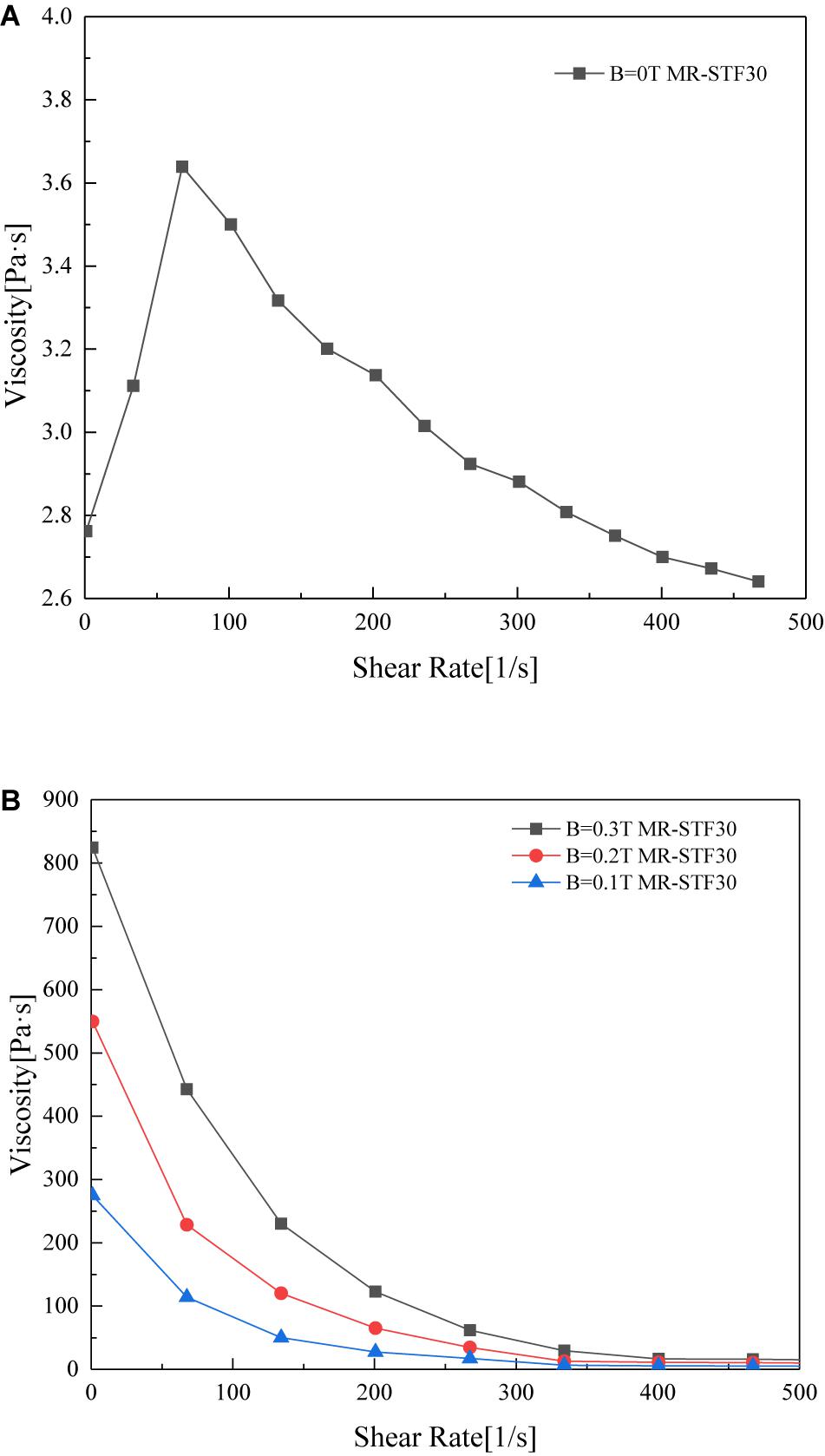
Figure 1. Measured curves between viscosity and shear rate of the MR-STF (A) without and (B) with magnetic field.
Structural Design and Theoretical Analysis of the Mechanical Model of the MRCSD
The displacement limit of the damper is designed based on the requirement of story displacement of a structure in an earthquake zone. According to the relevant provisions of the Code for Seismic Design of Buildings (GB 50011-2010) on the maximum floor displacement and floor height ratio (the limit value of the displacement angle between floors), if the height of a single floor is 3 m, there is 3 m × 1/50 = 60 mm, so the maximum design displacement of the damper is ± 60 mm. Considering the displacement of the structure at high frequency and small amplitude, the maximum compression of the decoupling spring is 4 mm.
Structural Design
In this paper, a MR shear thickening fluid with shear thickening effect and MR effect is manufactured. Based on the rate sensitivity and magnetic sensitivity of the MR shear thickening fluid, a MRCSD is designed, which is suitable for various vibration excitation environments and has the function of anti-impact energy dissipation. The basic structure of the damper is shown in Figure 2. It mainly consists of a piston rod, a cylinder, a piston, front and rear end caps, coils, and permanent magnets.
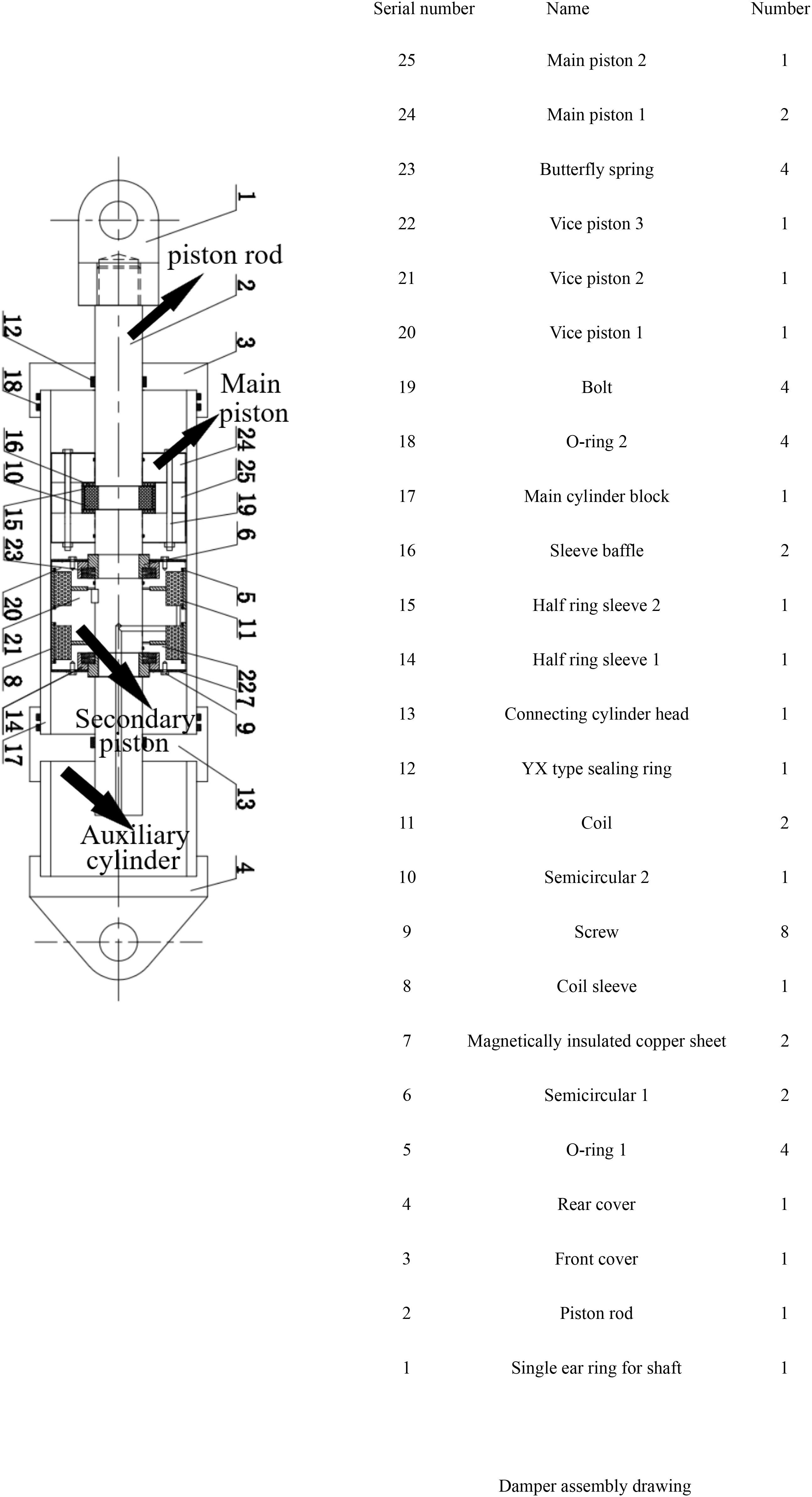
Figure 2. Structural form of the MRCSD.
Working Principle
The MRCSD has two working units: the main piston part and the auxiliary piston part. The main piston part bears the function of shock resistance and energy dissipation. Through the design of a permanent magnet and an excitation coil, the auxiliary piston part can realize the energy dissipation with continuous variable damping.
The basic working principle of the MRCSD is as follows: The MRCSD is designed with a parallel connection of the main piston part of the anti-impact energy dissipation and the sub-piston part with dual characteristics of MR effect and shear thickening effect. The damper designed in this paper drives the piston to move under the excitation of the external environment. When the seismic displacement is small, the energy dissipation performance is low. The main piston starts to work. With the increase of the displacement, the permanent magnet arranged in the secondary piston produces the MR effect in the working gap between the secondary piston and the main cylinder body, and the energy dissipation performance of the damper increases. When the seismic displacement is large, the energy dissipation performance of the damper increases. After the main piston and the auxiliary piston work together, the output of the damping force can be adjusted by controlling the current. The dual characteristics of the MR effect and the shear thickening effect at the working clearance of the auxiliary piston can be realized, and the vibration reduction effect of the impact energy dissipation and the damping energy dissipation can be achieved. Finally, the effect of continuous variable damp and energy dissipation can be achieved.
Theoretical Analysis of the Mechanical Model
Aiming at a new type of MR stage damper designed in this paper, the mechanical model theory of a MR stage damper is put forward. The basic design parameters of damper structure can be derived from the damping force formula of shear valve viscous damper (Chen, 2012) and can be given by
In the model,R1 is the inner diameter of the damper cylinder block, r is the radius of the piston rod,R2 is the radius of the main piston,L1 is the width of the main piston, K is the dynamic viscosity of the fluid medium, m is the flow index,h1 is the working clearance of the main piston, and V is the velocity of the piston.
According to the different simplified forms, there are different theoretical calculation formulas for the damping force of shear valve type MR dampers, but the most widely used formula which can directly reflect the relationship between damping force and physical parameters is (Yu et al., 2012)
where F is the damping force, L is the effective length of the piston, D is the inner diameter of the cylinder block, d is the diameter of the piston rod, h is the working clearance, V is the moving speed of the piston, τy is the shear yield strength of the MR fluid, and η is the zero-field apparent viscosity of the MR fluid.
The dynamic viscosity of the fluid medium can be derived by introducing the correction term Eq. (2) and can be expressed as
where S is the amplitude of the damper, C is the maximum compression of the disk spring, and k is the elastic constant of the disk spring.
where F is the damping force of the damper,K(x) is the damping force of the dish spring,F1 is the damping force of the main piston of the damper,L2 is the effective length of the auxiliary piston, andh2 is the working clearance of the auxiliary piston.
Equation 4 provides the guidelines for the design of the size of the MRCSD. After repeated adjustment of the design process, the basic structural parameters of the MRCSD are shown in Table 2.
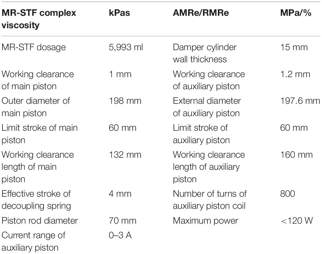
Table 2. Basic structural parameters of the MRCSD.
Magnetic Circuit Design
Finite Element Simulation of the Magnetic Circuit
The magnetic circuit of the MRCSD mainly includes the magnetic circuit of the auxiliary piston. The magnetic circuit of the auxiliary piston is simulated by the finite element method to determine the parameters of the magnetic circuit. Next, the finite element model of the auxiliary piston is established by using the ANSYS software developed by ANSYS Corporation in the United States. The size of the permanent magnet in the magnetic circuit and the number of turns of the excitation coil are determined by the finite element simulation analysis of the auxiliary piston.
Figure 3A shows the finite element model of the auxiliary piston. A1 is 45 steel; A2 is MR fluid; A3 is air; A4 and A5 are excitation coils; A6 is 0Cr18Ni9 stainless steel; and A7 and A8 are N30 NdFeB permanent magnets. Considering the opposite direction of coercivity of A7 and A8, they are defined as two kinds of materials, respectively, when defining material properties. Figure 3B shows its finite element meshing diagram, in which the number of elements is 24,085 and the number of nodes is 24,397.
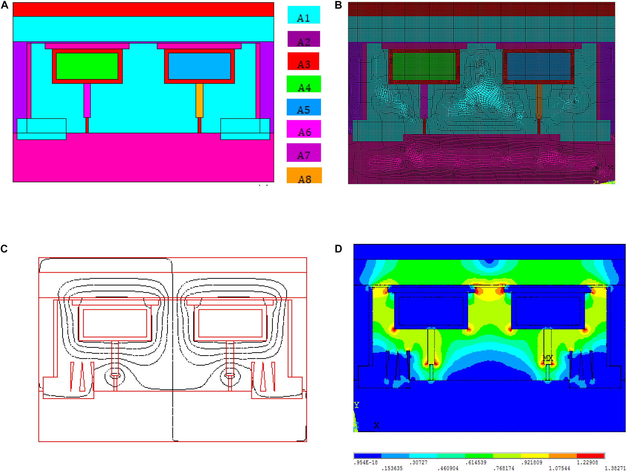
Figure 3. Finite element model of magnetic circuit structure and results: (A) material partition, (B) finite element mesh, (C) distribution of magnetic lines, and (D) total flux density distribution.
The distribution nephogram of the magnetic line and the magnetic induction intensity of the magnetic circuit of the auxiliary piston is shown in Figures 3C,D.
Magnetic Induction Curve
When the input current I of the excitation coil varies between −2 and 2 A, different magnetic induction intensities can be obtained at the working gap, as shown in Figure 4. When the current is in the positive direction, the magnetic induction intensity at the working gap increases with the increase of the current, and with the increase of the current, the increase of the magnetic induction intensity at the working gap decreases, which is caused by the nonlinearity of the material permeability and the saturation magnetic induction intensity close to the material. When the current is negative, the magnetic induction intensity at the working gap decreases with the increase of the current. It can be seen that the interaction between permanent magnet and excitation coil not only realizes the bidirectional adjustment of the damping force of the auxiliary piston but also ensures the output of the damper in case of power failure. It can also be seen from the figure that the magnetic induction intensity in the damping channel mainly concentrates on the magnetic poles, and the magnetic induction intensity between the poles is very small. Therefore, the magnetic induction intensity at each pole can be approximately considered when calculating the damping force of MR dampers.
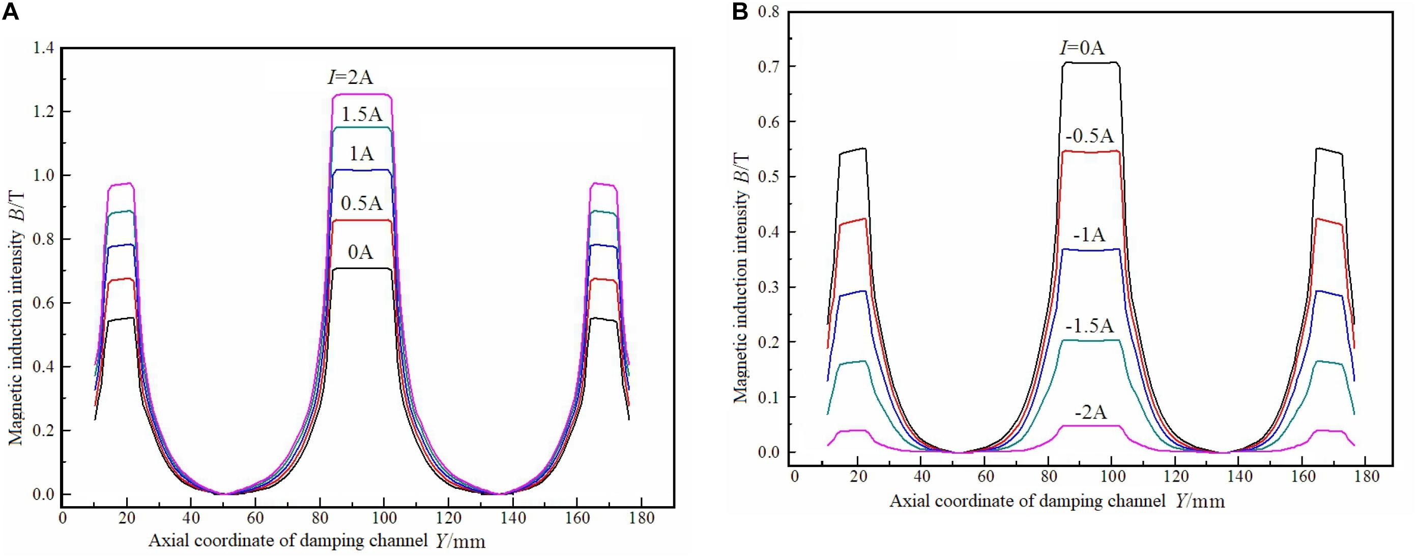
Figure 4. Magnetic induction intensity at working clearance of subpiston. (A) Current I is positive. (B) Current I is negative.
After the preparation of the MR-STF material, the design of magnetic circuit structure, and simulation analysis, a MRCSD is manufactured. The main components and the overall diagram of the damper are shown in Figure 5.
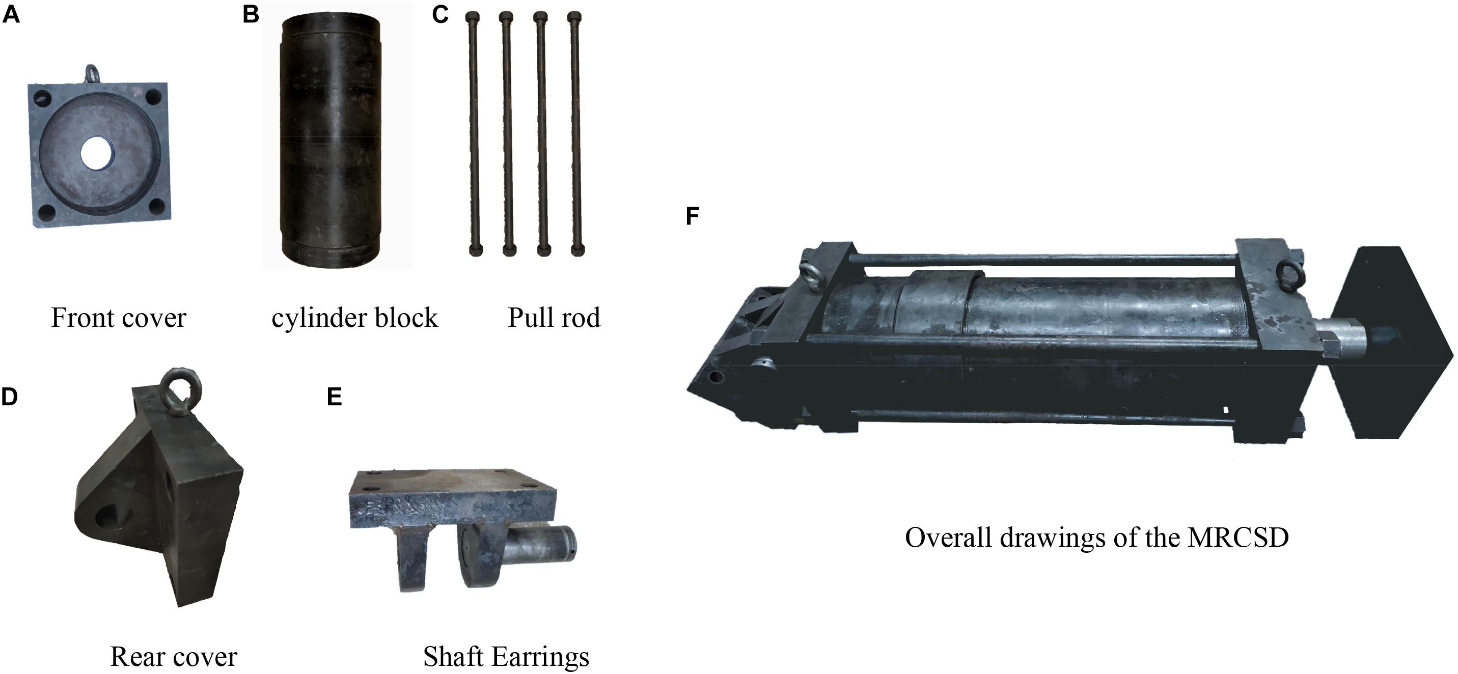
Figure 5. Main components and overall drawings of the MRCSD: (A) front cover, (B) cylinder block, (C) pull rod, (D) rear cover, (E) shaft earrings, and (F) overall drawings of the MRCSD.
Performance Test of the MRCSD
The shear performance test machine of the MRCSD adopts the SDS-300 servo dynamic and static test machine provided by the National Mechanical Experiment Center of Hohai University. The experimental setup is shown in Figure 6. The DC power supply is used to connect the excitation coil of the damper secondary piston. During the experiment, the displacement amplitude of the damper is controlled, and the mechanical properties of the damper are tested under the conditions of small displacement, large displacement, and impact. The maximum displacement is 4 mm in the case of small displacement and 60 mm in the case of large displacement, and the input current range was −2 to 2 A.
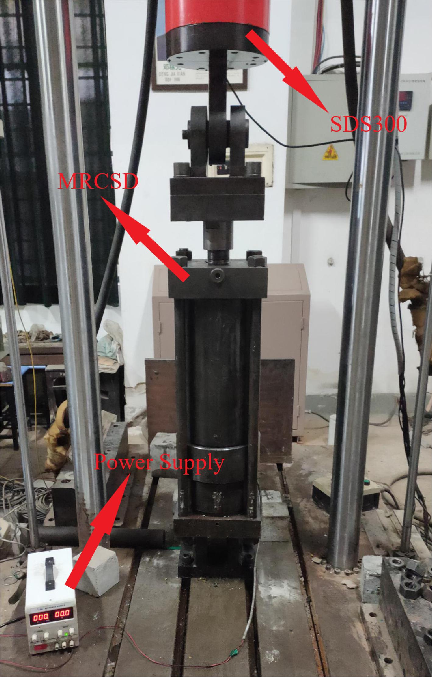
Figure 6. Experimental device of the MRCSD.
Under different working conditions, the test results of the MRCSD are shown in Figure 7.
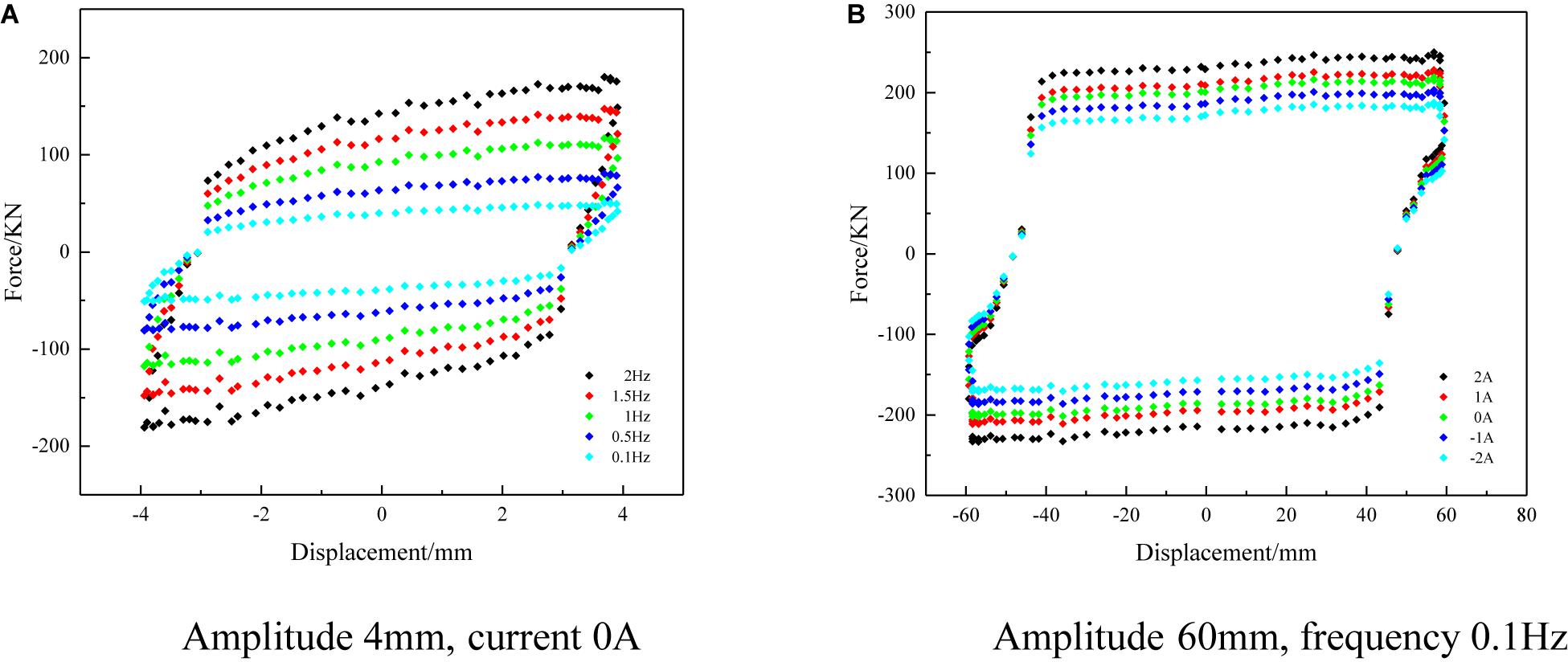
Figure 7. Model and experimental results for force-displacement relationship curves: (A) small displacement and (B) large displacement.
Figure 8 shows the load displacement curve of the MRCSD when a different current is applied under different working conditions. It can be seen from the figure that the damping force of the damper increases with the increase of the current and decreases with the decrease of the current, while the damping force changes linearly with the current.
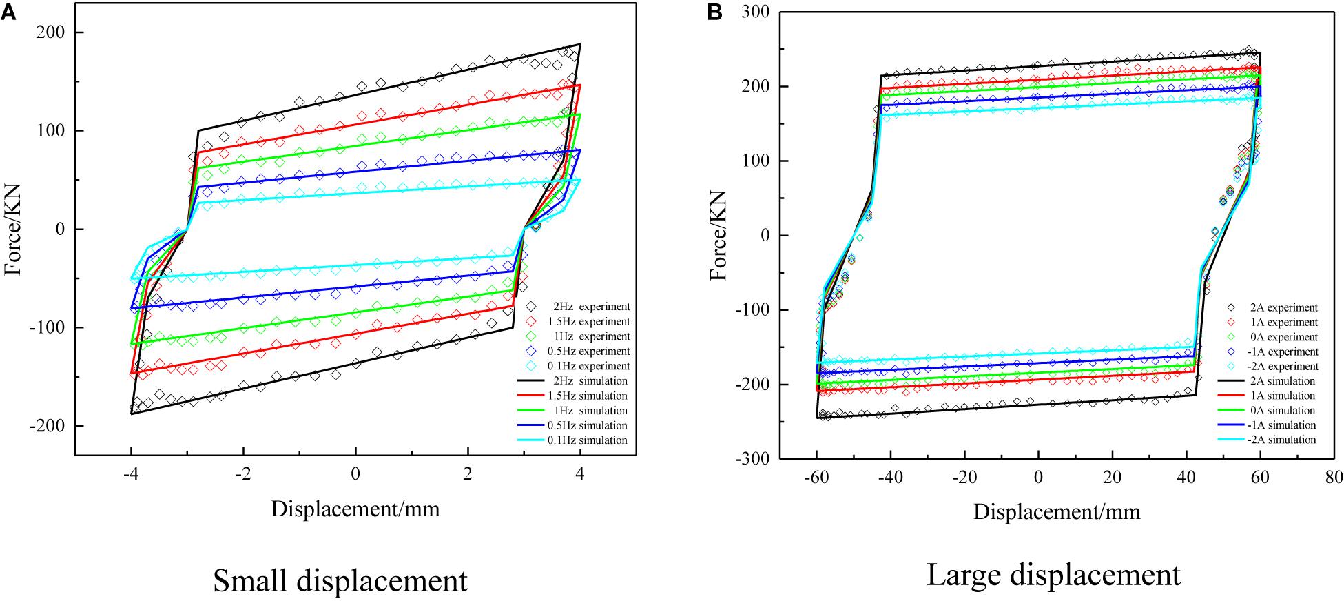
Figure 8. Load displacement curve of MRCSD under different working conditions. (A) Amplitude of 4 mm, current of 0 A. (B) Amplitude of 60 mm, frequency of 0.1 Hz.
(1) Under the condition of small displacement of a different current, that is, when the amplitude of the damper does not exceed the maximum compression of the Belleville spring by 4 mm, only the main piston works alone, and the dynamic characteristic curve of the damper is shown in Figure 7A. The curves of damping force in the figure are inclined to some extent, which is caused by the influence of the Belleville spring. When the piston rod deviates from the balance position, it compresses the spring, and the damping force of the damper increases with the increase of displacement; when the piston rod returns to the balance position, the spring loosens and the damping force decreases with the decrease of the displacement.
(2) Under the condition of large displacement of different current, that is, when the amplitude of the damper exceeds the maximum compression of the Belleville spring by 4 mm, the main piston and the auxiliary piston work together. The load displacement curve of the damper is shown in Figure 7B. It can be seen from the figure that both sides of the damping force curve incline to a certain extent, which is caused by the disk spring when the piston rod returns to the balance position from the maximum displacement. Similarly, this characteristic is also beneficial to the vibration control of the structure.
Compared with the damper output under small displacement and large displacement, it can be seen that under small displacement, the adjustable range of the damper output is 37.5–170.6 kN, and the adjustable multiple of the damping force is about 4.5; under large displacement, the adjustable range of the damper output is 192.8–250.2 kN, and the adjustable range of the damping force is about 1.3. It can be seen that for the MRCSD, in the case of small displacement, the output of the damper is smaller, but the adjustable multiple is higher. In the case of large displacement, the adjustable multiple of the damping force is smaller, but the maximum output of the damper is larger. Compared with the traditional oil damper, the MRCSD is more suitable for the vibration control of civil engineering structures.
The hysteretic curves of load displacement under different loads, strokes, and frequencies can reflect the damping dissipation capacity of the device. The test data and theoretical calculation data of the damper’s damping characteristics can be seen in Table 3.
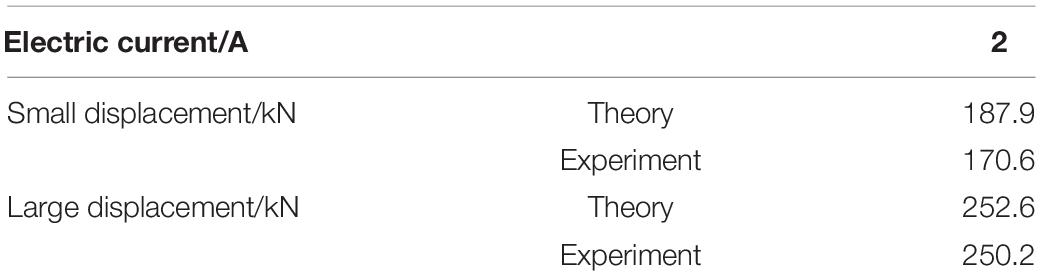
Table 3. Comparison of theoretical value and experimental value.
Mechanical Model and Parameters Identification
Mechanical Model of the MRCSD
It can be seen from the analysis of the mechanical characteristics of the damper that the damping force of the MRCSD is delayed relative to the input displacement. This phenomenon of energy loss is generally called “hysteresis.” In order to better describe the mechanical characteristics of the MRCSD, due to the effect of the disk spring, and considering the hysteresis characteristics of the MR damping force and the space phenomenon. Therefore, in combination with Formula (1), the correction formula of the damping force model of the anti-impact energy dissipation damper is shown in Eq. (4):
Among them,
where S is the amplitude of the damper, x0 is the absolute value of the lag critical displacement, x1 is the space of the damper, C is the maximum compression of the Belleville spring, and k is the elastic constant of the Belleville spring.
Parameters Identification
In this paper, the test data of small displacement and large displacement at 0.1 Hz excitation frequency are selected to identify the parameters of the mechanical model. Figure 7 shows the comparison of the experimental results and fitting curves of small displacement and large displacement under different currents. It can be seen from the figure that the dynamic model can well describe the force displacement hysteretic curve of the MRCSD.
It can also be seen from the corresponding force–velocity relationship curve shown in Figure 9 that the damper force has strong speed sensitivity when the small displacement is shifted, and the damping force increases rapidly when the speed increases. At the same time, the force–speed curve of the damper is fuller when the size displacement is lowered. When the speed increases, the damping force decreases, and the damping force increases when the velocity decreases. There is an obvious damping force lag phenomenon, and the damping force lag phenomenon should be fully considered when establishing the mathematical model of the damper.
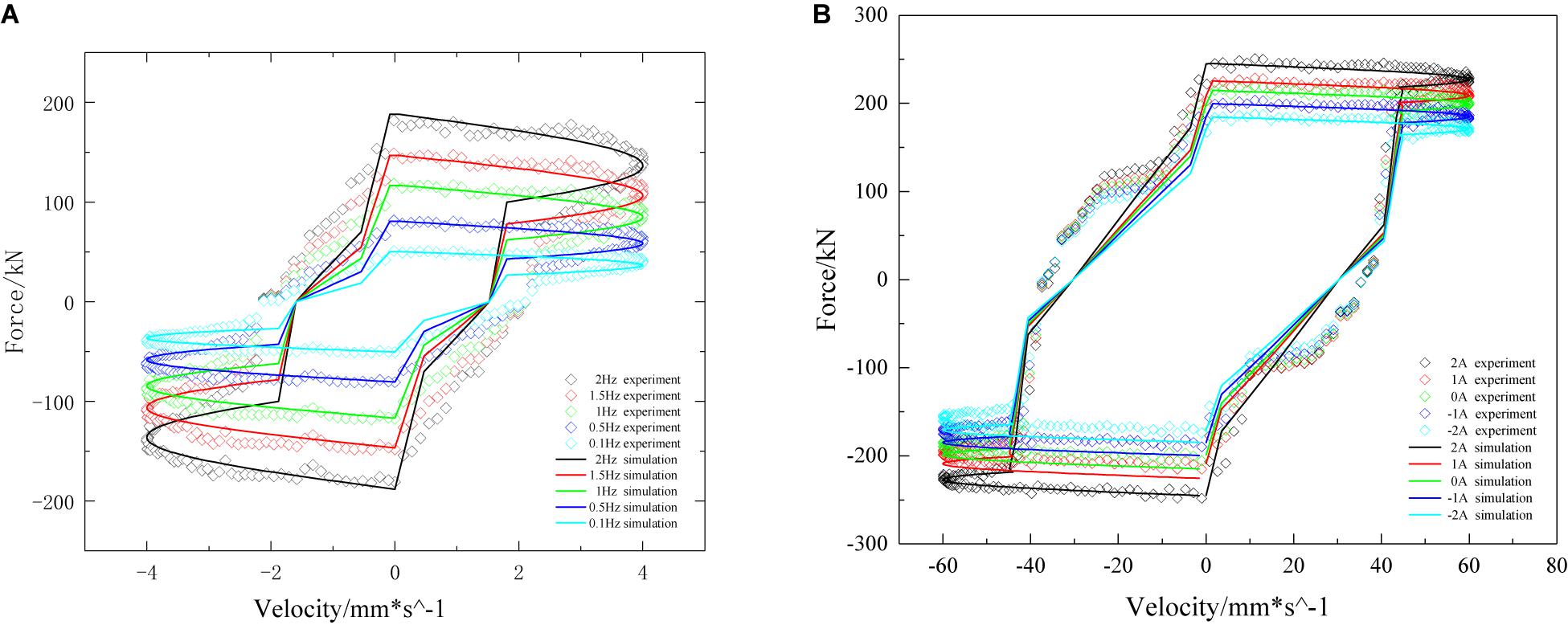
Figure 9. Force–velocity relationship curves: (A) small displacement and (B) large displacement.
Conclusion
In this paper, a MRCSD is designed and developed, which can be adapted to the environment of different vibration excitation frequencies. The dynamic mechanical properties of the damper are tested. Based on the comparison between the test results and the theoretical calculation results, the rationality and correctness of the intelligent damper design are verified. Some conclusions can be drawn as follows:
(1) The MR shear thickening fluid used in the damper was prepared and its dynamic mechanical properties were tested. The experimental results show that when the mass fraction of iron particles is lower than a certain value, the MR effect and shear thickening behavior can be observed. At the same time, the new intelligent fluid can be controlled by magnetic field and shear rate. With the concentration of iron particles, the shear thickening effect of the MR-STF is inhibited, while the MR effect is more obvious.
(2) We analyze the development process of MRCSD from the magnetic circuit finite element analysis and structural finite element analysis. The finite element results show that: (1) the structure size and the number of turns of the coil meet the design index, and the magnetic field utilization rate of the magnetic circuit design is higher; (2) with the increase of the positive current, the magnetic induction intensity in the working area gap increases gradually; (3) with the increase of the negative current, the magnetic induction intensity in the working area gap decreases gradually.
(3) The experimental results of the proposed damper show that the MRCSD has the characteristics of control damping, and can achieve the effect of isolation and vibration reduction under different earthquake intensities. The maximum output of the damper can reach 250.2 kN. These indicate that the damper achieves the expected design goal.
Data Availability Statement
The original contributions presented in the study are included in the article/supplementary material, further inquiries can be directed to the corresponding author/s.
Author Contributions
All authors listed have made a substantial, direct and intellectual contribution to the work, and approved it for publication.
Funding
This work was supported by the National Natural Science Foundation of China (Grant No. 51508237) and the Primary Research and Development Plan of Jiangsu Province (Grant No. BE2017167).
Conflict of Interest
The authors declare that the research was conducted in the absence of any commercial or financial relationships that could be construed as a potential conflict of interest.
References
Brown, E., and Jaeger, H. M. (2014). Shear thickening in concentrated suspensions: phenomenology, mechanisms and relations to jamming. Rep. Prog. Phys. 77:046602. doi: 10.1088/0034-4885/77/4/046602
Chen, W. (2012). Theoretical and experimental study on viscous dampers. Huazhong Univ. Sci. Technol. 2020:3025863.
Chen, W., Du, C., and Wan, F. (2010). Effects of surfactants and thixotropic agents on the sedimentation stability of magnetorheological fluids. Funct. Mater. Dev. 141, 55–58.
Choi, S., Li, W., Yu, M., Li, W., Yu, M., Du, H., et al. (2016). State of the art of control schemes for smart systems featuring magneto-rheological materials. Smart Mater. Struct. 25:043001. doi: 10.1088/0964-1726/25/4/043001
Dullens, R. P. A., and Bechinger, C. (2011). Shear thinning and local melting of colloidal crystals. Phys. Rev. Lett. 107:138301.
Feng, L., Liu, S., Zhao, J., Wang, X., and Zhao, D. (2019). The design of an innovative multi-winding magnetorheology damper featuring embedded flow passage. Smart Mater. Struct. 562:012141. doi: 10.1088/1757-899x/562/1/012141
Guo, Y. Q., Zhang, J., He, D.-Q., and Li, J.-B. (2020). Magnetorheological elastomer precision platform control using OFFO-PID algorithm. Adv. Mater. Sci. Eng. 2020:3025863.
Kruti, S., Phu, D. X., and Choi, S. -B. (2014a). Rheological properties of bi-dispersed magnetorheological fluids based on plate-like iron particles with application to a small-sized damper. J. Appl. Phys. 115:203907. doi: 10.1063/1.4879681
Kruti, S., Phu, D. X., Seong, M., and Upadhyay, R. V. (2014b). A low sedimentation magnetorheological fluid based on plate-like iron particles, and verification using a damper test. Smart Mater. Struct. 23:027001. doi: 10.1088/0964-1726/23/2/027001
Liang, J. (2013). Design and testing of shock transmission device for bridge protection. Appl. Mech. Rev. 405–408, 1517–1520. doi: 10.4028/www.scientific.net/amm.405-408.1517
Liang, J., and Ou, J. (2006). Viscous damping control analysis of wind-induced buffeting of long-span cable-stayed bridge deck. Seism. Eng. Eng. Vibr. 26, 139–144.
Liang, J., and Zhang, X. H. (2015). Rheological properties of SP in shock transmission application. J. Mater. Civil Eng. 27:04014250. doi: 10.1061/(asce)mt.1943-5533.0001227
Liu, M. (2019). Study on performance optimization and application of shear thickener. China Univ. Sci. Technol., China.
Liu, P., Ma, L., Wang, B., and Wang, Z. (2018). Study on the new type of permanent magnet MR damper for stay cable and its parameter optimization. Bridge Construct. 48, 51–55.
Ou, J. P., and Li, H. (2009). Design approaches for active, semi-active and passive control systems based on analysis of characteristics of active control force. Earthq. Eng. Eng. Vibr. 8, 493–506. doi: 10.1007/s11803-009-9119-z
Peters, I. R., Majumdar, S., and Jaeger, H. M. (2016). Direct observation of dynamic shear jamming in dense suspensions. Nature 532, 214–217. doi: 10.1038/nature17167
Picano, F., Breugem, W. P., Mitra, D., and Brandt, L. (2013). Shear thickening in non-Brownian suspensions: an excluded volume effect. Phys. Rev. Lett. 111:098302.
Qin, J., Zhang, G., and Shi, X. (2017). Shear thickener and its composite materials. Eng. Design Guides 31, 59–64.
Seto, R., Mari, R., Morris, J. F., and Denn, M. B. (2013). Discontinuous shear thickening of frictional hard-sphere suspensions. Phys. Rev. Lett. 111:218301.
Trulsson, M., Andreotti, B., and Claudin, P. (2012). Transition from the viscous to inertial regime in dense suspensions. Phys. Rev. Lett. 109:118305.
Wei, X., Sun, R., and Wang, Q. (2017). Properties of shear thickening liquid and its application in flexible stab resistant materials. Synthet. Fiber 46, 40–43.
Wu, Z. (2018). Study on Energy Consumption Characteristics of Shear Thickening Liquid and Its Application in Vehicle Impact Resistance. Nanjing: Nanjing University of Aeronautics and Astronautics.
Wyart, M., and Cates, M. E. (2014). Discontinuous shear thickening without inertia in dense non-Brownian suspensions. Phys. Rev. Lett. 112:098302.
Xu, Z., Shen, Y., and Guo, Y. (2003). Semi-active control of structures incorporated with magnetorheological dampers using neural networks. Smart Mater. Struct. 12, 80–87. doi: 10.1088/0964-1726/12/1/309
Xu, Z. D., Liao, Y. X., Ge, T., and Xu, C. (2016). Experimental and theoretical study of viscoelastic dampers with different matrix, rubbers. J. Eng. Mech. 2016:04016051. doi: 10.1061/(asce)em.1943-7889.0001101
Xu, Z. D., and Shen, Y. P. (2003). Intelligent Bi-state control for the structure with magnetorheological dampers. J. Intellig. Mater. Syst. Struct. 14, 35–42. doi: 10.1177/1045389x03014001004
Yang, Y., Xu, Z.-D., Xu, Y.-W., and Guo, Y.-Q. (2020). Analysis on influence of the magnetorheological fluid microstructure on the mechanical properties of magnetorheological dampers. Smart Mater. Struct. 29:115025. doi: 10.1088/1361-665x/abadd2
Yi, C. (2011). Preparation, Performance Test and Constitutive Model of MR Fluid. Chongqing: Chongqing University.
Ying, Q., Wen, H. X., and Jing, X. (2019). Study on structures incorporated with MR damping material based on PSO algorithm. Front. Mater. 6:37. doi: 10.3389/fmats.2019.00037
Yu, G., Du, C., and Wan, F. (2012). Design and performance test of high energy consumption self decoupling MR damper. Vibr. Test Diagn. 32, 426–431.
Yu, M., Li, B., Niu, Z., Xue, W., and Zhao, P. (2019). Study on dynamic characteristics of variable damping vibration isolator based on shear thickening liquid. Equip. Environ. Eng. 16, 33–38.
Zhang, X. Z., Li, W. H., and Gong, X. L. (2008). The rheology of shear thickening fluid (STF) and the dynamic performance of an STF-filled damper. Smart Mater. Struct. 17, 035027.1–035027.7.
Zhao, P., Yu, M., Chen, Q., and Wu, Z. (2018). Buffer mechanism and mechanical properties of shear thickening liquid. J. Vibr. Eng. 31, 966–973.
Zhou, H., Yan, L. X., Jiang, W. Q., Xuan, S. H., and Gong, X. (2016). Shear thickening fluid-based energy-free amper: design and dynamic characteristics. J. Intellig. Mater. Syst. Struct. 27, 208–220. doi: 10.1177/1045389x14563869
Zhou, Y., Zhu, W., and Rui, X. (2017). Design and performance analysis of dual exit MR damper. Noise Vibr. Control. 37, 178–181.
Keywords: magnetorheological shear thickening fluid, magnetic rate controlled stage damper, magnetic field finite element method, parameter identification, performance analysis
Citation: Yu G-J, Zhu S-J, Du C-B, Wang L-Y and Huang J-C (2021) Design and Performance Test of a Magnetic Rate Controlled Stage Damper. Front. Mater. 8:640316. doi: 10.3389/fmats.2021.640316
Received: 11 December 2020; Accepted: 06 April 2021;
Published: 10 May 2021.
Edited by:
Janusz Goldasz, Cracow University of Technology, PolandReviewed by:
Zhao-Dong Xu, Southeast University, ChinaXuan Shouhu, University of Science and Technology of China, China
Xianzhou Zhang, Independent Researcher, Tomago, Australia
Copyright © 2021 Yu, Zhu, Du, Wang and Huang. This is an open-access article distributed under the terms of the Creative Commons Attribution License (CC BY). The use, distribution or reproduction in other forums is permitted, provided the original author(s) and the copyright owner(s) are credited and that the original publication in this journal is cited, in accordance with accepted academic practice. No use, distribution or reproduction is permitted which does not comply with these terms.
*Correspondence: Guo-Jun Yu, gjyu9@ujs.edu.cn