 Deren Lu1
 Faxing Ding
94% of researchers rate our articles as excellent or good
Learn more about the work of our research integrity team to safeguard the quality of each article we publish.
Find out more
ORIGINAL RESEARCH article
Front. Mater. , 13 April 2021
Sec. Structural Materials
Volume 8 - 2021 | https://doi.org/10.3389/fmats.2021.629819
This article is part of the Research Topic Composite Use of High Strength Steel and Concrete Materials for Sustainable Civil Engineering View all 9 articles
This paper presents an experimental and numerical study on large dimension concrete-filled square low steel ratio steel tubular (CFST) stub columns under axial loading. Four specimens were designed to investigate the effects of steel ratio on the confinement effect of square CFST stub columns with a low steel ratio. ABAQUS was used to establish 3D finite element (FE) models for simulation of square CFST stub columns with a low steel ratio under axial loading. Furthermore, based on the experimental verification, the definition of the confinement index (ϕ = fsAs/(fcAc)) was discussed and the effect of the grade of concrete and steel tube was also investigated. With the same cross-sectional dimensions, the confinement effect of the square CFST stub columns with a low steel ratio (less than 0.05) was better than the others. The stub columns with the yield strength of steel tube fs = 235 MPa (345, 420 MPa) and compressive cubic strength of concrete fcu = 40 MPa (60, 80 MPa) can give fully demonstrate the material performance and reflect the better confinement effect. Based on the experimental results and FE modeling, a practical calculation formula for the ultimate load-carrying capacity of square CFST stub columns with a low steel ratio was proposed. The formula calculation results presented in this paper show good agreement with the experimental results. Compared with the existing formulas, the proposed formula has better precision.
Square concrete-filled steel tubular (CFST) columns are widely used in high-rise buildings because of its advantages such as convenient construction of joints, large section moment of inertia, and easy to take fire prevention measures. While ensuring a certain steel ratio, the large size square CFST column in practical engineering is difficult to weld due to the excessive thickness of steel tube (Giakoumelis and Lam, 2004), so the application of the square CFST column with a low steel ratio in practical engineering is possible.
Nowadays, various strength construction materials are being increasingly used in engineering structures as a result of the continued advancement of materials technology. These materials often exhibit high strength as well. As far as CFST columns in real structures are concerned, the highest cylinder compressive strength and yield strength reported are 130 and 690 MPa for the concrete and steel, respectively (Uy, 2011). Therefore, the reasonable matching of steel tube and concrete with different strength grades helps make full use of material properties and provide reasonable suggestions for material selection in practical engineering design.
At present, Extensive experimental and analytical studies have been conducted to understand the behavior of the composite columns mainly from the 1960s (Shanmugam and Lakshmi, 2001; Nie et al., 2008; Zhu et al., 2016; Yang et al., 2019a; Yang et al., 2019b) and the available experimental research and theoretical analysis of the mechanical properties of square CFST columns (Sakino et al., 2004; Tao et al., 2008) are mostly focused on small and medium-sized sections, with the steel ratio generally greater than 0.05 (Tao et al., 2009; Wang et al., 2002; Kato, 1995; O shea and Bridge, 2000), while the square CFST columns with a steel ratio less than 0.05 are only limited used for a comparison test. Therefore, the practical calculation formula for the bearing capacity of square CFST columns proposed by most researchers does not take into account the stress situation of stub columns under low steel ratio. Such ignorance will produce certain errors in designing and calculating square CFST columns with a low steel ratio.
The limited study on square CFST columns with a steel ratio of less than 0.05 is summarized below. To study the influence of section shape, aspect ratio, concrete strength grade, and steel ratio on the mechanical properties of thin-walled CFST columns, Zhang (Zhang et al., 2005) carried out 26 specimens of thin-walled CFST short columns, and among them, there are three square CFST specimens with a steel ratio lower than 0.05. Mursi (Mursi and Uy, 2018) also carried out an experimental study on the mechanical properties of 30 square CFST columns with a square section size ranging between 126 and 306 and a steel ratio ranging between 0.040 and 0.103. Only five of the specimens were used as comparative tests with a steel ratio of less than 0.05. Lume et al. (Lume et al., 2017) proposed using high-strength thin-walled steel tubes to limit the high-strength concrete core, which can produce a confinement effect and enhance the strength. To this end, in an experimental study on the mechanical properties of 26 high-strength thin-walled CFST columns, the steel ratio was 0.01, the steel tube with yield strengths was greater than 500 MPa, and concrete with compressive strengths was 100 MPa. To improve the stability of the thin-walled concrete-filled steel tubular wall and the bearing capacity and ductility of the test piece, Li et al. (Bin et al., 2017) proposed to set stiffeners in the steel tube and carried out relevant tests. The steel ratio of the specimens was between 0.041 and 0.086. Zhou et al. (Zhou et al., 2019) proposed a scheme in which diagonal binding ribs are welded at all the four pairs of adjacent sides of the square tube to strengthen the load-bearing performance of thin-walled CFST columns, the steel ratio of the specimens was between 0.027 and 0.097. There are five square CFST columns with a steel ratio of less than 0.05 for comparison specimens.
In addition, the confinement effect of square CFST stub columns with a low steel ratio and the reasonable matching between steel tubes and concrete have not been thoroughly studied.
Therefore, this study is to investigate the mechanical properties of square CFST columns with a low steel ratio of less than 0.05 and the confinement effect of steel tube on concrete. More specifically, this study completed the following work. 1) The square CFST columns with different low steel ratio were tested under axial loading to investigate the effects of different steel ratio on the mechanical properties; 2) A three-dimensional solid finite element (FE) model of square CFST stub columns with low steel ratio was established to investigate the effects of steel ratio, concrete and steel strength on the internal forces and the confinement effect between square steel tubes and concrete. The definition of the confinement index (ϕ = fsAs/(fcAc)) is also discussed. The FE analysis also provides a basis for the reasonable matching of the material of the square CFST stub columns with low steel ratio; 3) A calculation formula for the bearing capacity of square CFST columns with low steel ratio is established with consideration of the stress situation of stub columns under low steel ratio. The comparison was also conducted with the existing formulas and specifications. The results will be beneficial to provide a theoretical basis and calculation basis for the design of large cross-section and low steel ratio square CFST columns that may exist in actual engineering and propose a reasonable choice of steel ratio and strength of steel and concrete.
A total of four square CFST stub columns with different steel ratios were designed. Details of specimen numbers and parameters are shown in Table 1. In the table, B is the width of the square section. t is the wall thickness of the steel tube. L is the height of the specimen. fcu is the cubic compressive strength of concrete. fs is the yield strength of steel. ρ is the steel ratio of steel tube, defined as the ratio of the steel tube area to the entire cross-sectional area (ρ = As/Asc). Nu,e is the ultimate load-bearing capacity of stub columns from experimental results. Nu,fe is the ultimate load-bearing capacity of stub columns from FE results.
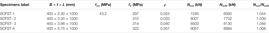
TABLE 1. Details of specimens and their load-bearing capacity.
To observe the deformation of the specimen after the damage, the red paint was sprayed on the outer surface of the empty steel tube specimen, and a 50 × 50 mm grid has meshed for all specimens. After the square steel tubes were formed, 10 mm-thick steel plates were welded onto the bottom of the tubes then concrete was poured from the top of the steel tube. The concrete is non-self-compacting commercial concrete. Before curing, care was taken that the surface of the concrete was level with the end of the steel tube. Standard cubic concrete specimens 150 mm in length were made and cured under the same condition. After 28 days of curing, the concrete had achieved its compressive strength and its surface was then flattened with a grinding machine. The compressive strength fcu of the concrete cube is measured by the standard cubic concrete specimens according to the Standard for Method of Mechanical Properties on Ordinary Concrete (GB/T50081-2019) (GB/T50081-2019, 2019). Finally, epoxy was applied onto the concrete surface and the end of the steel tube to bond a 10 mm-thick steel plate. This was done to ensure that concrete and steel tubes were loaded uniformly. The steel is processed by a cold-rolled steel sheet. The empty steel tube is bent into a U-face by Q235 steel plate, and then the two U-shaped steel tubes are butt welded. The butt weld is welded according to the “Standard for design of steel structures” (GB/50017-2017) (GB/50017-2017, 2017). The seam is designed with a weld height of 1 times the thickness of the steel plate and a margin of 1 mm outside the weld. Refer to “Metallic materials tensile test Part 1: Room temperature test method” (GB/T 228.1-2010) (GB/T 228.1-2009, 2010), and make three 4 mm-thick steel plate standard test pieces. The tensile test was carried out on a tensile tester according to standard test methods. The measured steel yield strength is 310 MPa, and the ultimate tensile strength is 460 MPa.
The compression test of square CFST stub column specimens with a low steel ratio was carried out on the 20,000 kN multifunctional testing system at the National Engineering Laboratory of High-speed Railway Construction Technology of Central South University. The load is transferred to the specimen through a 4 mm thick steel plate covering the top of stub column to ensure that the load surface is flat, and the pressure value applied to the specimen is directly read by the loading program. The displacement gauge is arranged symmetrically at 1/3 of the height of the specimen and connected to a data acquisition system to collect relative displacement. In order to measure the deformation of the steel tube at different positions, three strain rosettes were arranged in the middle of each specimen, and the axial and transverse strains of the steel tube at three different positions were collected by the strain test system. Figure 1 shows the schematic diagram of displacement gauge and strain flower arrangement, and the picture of typical specimen compression.
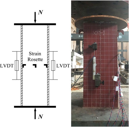
FIGURE 1. Experimental instrumentation for all specimens.
The specimen was pre-loaded to ensure that the pressure surface is flat. The hierarchical loading method mentioned in the literature (Ding et al., 2020) was adopted until the specimen is close to the ultimate load. When the ultimate load was approached, specimens were loaded slowly and continuously until final failure.
At the initial stage of the test loading, the specimen is in the elastic working stage, and its load-strain curve increases linearly. When the imposed load reached 60–70% of the ultimate load, the steel began to yield and the load (N) and axial strain (εL) curves demonstrated nonlinear elastic-plastic behavior, as shown in Figure 2. When the specimen reaches the ultimate load, the steel tube buckles locally, and the core concrete is shear-type displaced and crushed. The local buckling of steel tubes of all specimens did not occur until the ultimate load was approached. The typical failure modes of the SCFST stub columns with a low steel ratio show the drumming damage near the end of the specimen. After the loading, the Plumb line method is used to measure the bulge on all sides of the steel tube, and the maximum value is applied. The maximum drum value of the specimen SCFST-1 is 31mm, while the maximum drum value of the specimen SCFST-2, SCFST-3, and SCFST-4 are 23, 22 and, 18 mm, respectively. It can be seen that the increase of the wall thickness of the steel tube strengthens the stability of the steel tube wall, effectively delays and slows the buckling of steel tube, and the typical failure mode is shown in Figure 3.
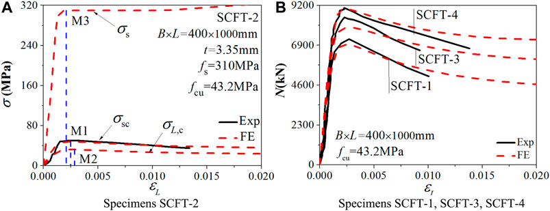
FIGURE 2. Load (stress)-axial strain curves of stub columns under axially loading.
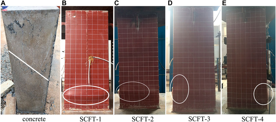
FIGURE 3. Typical failure modes of specimens.
Finite element (FE) models are established using the ABAQUS finite element software. In these models, the 8-node reduced integral format 3D solid element (C3D8R) is chosen to model the core concrete and cover plate. The square steel tube adopts a 4-node reduced integral format shell unit (S4R), and uses nine nodes of Simpson integral along the thickness direction of the shell unit to meet the calculation accuracy requirements. The structured meshing technique is adopted as shown in Figure 4.
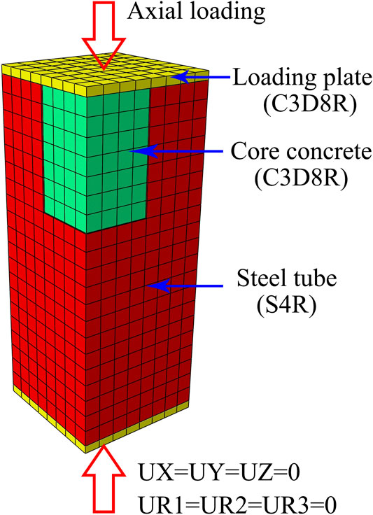
FIGURE 4. Mesh generation of FE models.
In these models, a surface-based interaction with “hard” contact in the normal direction and the Coulomb friction coefficient of 0.5 in the tangential direction is used to simulate the interfacial behavior between the steel tube and the core concrete, cover plate, and core concrete. The sliding formulation is finite sliding in the contact interaction. The “tie” option is adopted for the constraint between the steel tube and the cover plate so that no relative motion occurs between them.
The following non-dimensional mathematical form for the stress-strain relationship of concrete under uniaxial compression was proposed in (Ding et al., 2019):
where k is the ratio of the initial tangent modulus to the secant modulus at peak stress and equals
An elasto-plastic model, with consideration of Von Mises yield criteria, Prandtl-Reuss flow rule, and isotropic strain hardening, was used to describe the constitutive behavior of steel. The expression for the stress-strain relationship of steel was:
where σi is the equivalent stress of steel; fs is the yield strength; fu is the ultimate strength, and fu = 1.5 fs; Es is the elastic modulus, Es=2.06 × 10⁵ MPa; Est is the strengthening modulus, which is described by Est = ζEs; εi is the equivalent strain; εy is the yield strain; εst is the strengthening strain; and εu is the ultimate strain, which is described by εu = εst + 0.5fs/(ζEs), where εst = 12εy, εu = 120εy and ζ = 1/216.
The results calculated by the FE model are compared with the experimental results. Figure 2A takes the specimen SCFST2 as an example to compare the changing trends of overall stress of the specimen (σsc = N/Asc, Asc = Ac + As), the stress of the steel tube (σs), and the stress of the concrete (σL,c). It can be seen from the results that the σs reaches yield strength (point M3) before the σsc reaches the maximum value (point M1, that is, the bearing capacity), and the σL,c reaches the extreme (point M2) after the bearing capacity. Table 2 lists the axial strain values of each specimen at each characteristic point. As shown in the table, all the steel tubes of specimens first reach the yield strength. That means the steel tube will not buckle until the stub columns reaches the bearing capacity. Figure 2B is a comparison of the load-axial deformation curve of other specimens between the FE results and the test results.
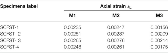
TABLE 2. Details of specimens and their load-bearing capacity.
Comparisons of axial strain (εL) curves and transverse strain (εθ,S) curves at the strain gauge location between experimental and FE results are shown in Figure 5. It can be seen that the test curve in the elastic phase is in good agreement with the FE calculation curve. In the elasto-plastic phase and the plastic phase, the difference between the FE calculation curve and the test curve becomes larger. That is mainly because of the internal defects of steel tubes and concrete FE which has not been considered into the simulation process. Such limitation caused that, the buckling and failure of the actual specimen could not be fully captured in FE analysis.
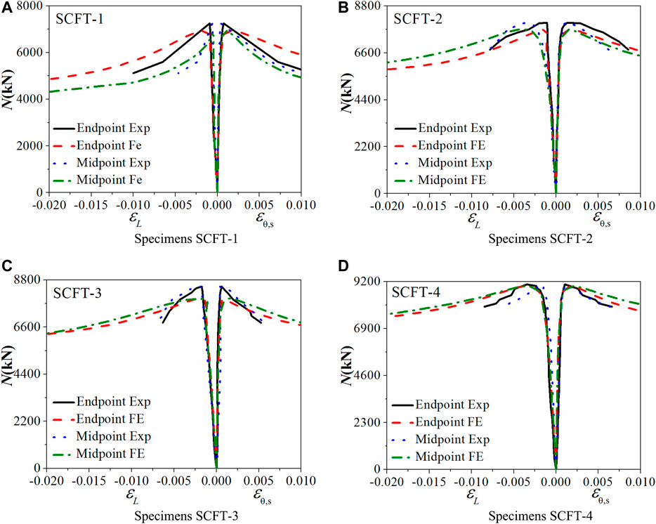
FIGURE 5. Comparison of load-strain curve of FE calculation results and test results.
Figure 6A shows the comparison of the bearing capacity of the FE calculation of the specimen with the experimental value. The accurate value about the results of load-bearing capacity modeled by FE (Nu,fe) and the experimental results (Nu,e) for all specimens have been shown in Table 1. The average ratio of Nu,e to Nu,fe is 1.037 with a dispersion coefficient of 0.026. Based on the comparison, the FE results agree well with the experimental results, with only slight underestimates.
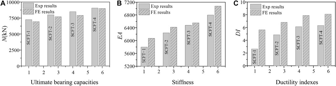
FIGURE 6. Comparison of ultimate bearing capacities, stiffness and ductility indexes for all specimens.
The comparison between the measured and calculated values of the stiffness is shown in Figure 6B. The stiffness is defined as the secant stiffness at the 40% ultimate load corresponding to the load-axial strain rise section curve. It can be seen that the stiffness calculated by the FE is slightly larger. Simultaneously, according to the test results, the stiffness of the specimen SCFST-2 is increased by 5.7% compared with the specimen SCFST-1, and the stiffness of the specimen SCFST-3 is improved by 8.0% compared with the specimen SCFST-1. And compared with the specimen SCFST-1, the specimen SCFST-4 has a stiffness increase of 15.9%, which indicates that increasing the wall thickness is beneficial to improve the stiffness of the specimen.
The comparison between measured and calculated values of ductility is shown in Figure 6C. The ductile DI definition of square CFST stub columns is shown in the literature (Ding et al., 2019). Since the FE calculation is difficult to effectively simulate the buckling and failure of the specimen, the FE results overestimate the ductility of all specimens. Simultaneously, according to the test results, the ductility of the specimen SCFST-2 was increased by 20.8% compared with the specimen SCFST-1, and the ductility of the specimen SCFST-3 was improved by 40.0% compared with the specimen SCFST-1. And compared with the specimen SCFST-1, the specimen SCFST-4 increased the ductility by 43.6%, indicating that the ductility of the specimen increased with the increase of the wall thickness.
In sum, as the steel ratio increases, the stiffness and ductility of the specimen can be improved. The effect of steel ratio on the restraint between steel tube and concrete and the different restraint efficiency of different steel ratios will be discussed and studied in detail through parametric FE analysis. Simultaneously, the reasonable match of steel tubes and concrete with different strength grades will also be discussed.
The variation law of the ratio of axial average maximum stress of core concrete calculated by finite element model to the uniaxial compressive strength of concrete with the steel ratio is shown in Figure 7A. The variation law of the ratio of finite element calculation ultimate load-carrying capacity to nominal ultimate load-carrying capacity with the steel ratio is shown in Figure 7B. The variation law of the ratio of three sets of axial compression test ultimate load-carrying capacity to nominal ultimate load-carrying capacity with the steel ratio is shown in Figure 7C. It can be seen that the Nu/No and fL,c/fc of the specimen have the maximum value when the steel ratio(ρ) is 0.04, which indicates that the steel tube has the most confinement effect on the core concrete in the case of the steel ratio is 0.04. The axial compression test results of different literatures shown in Figure 7C also reflect similar laws.
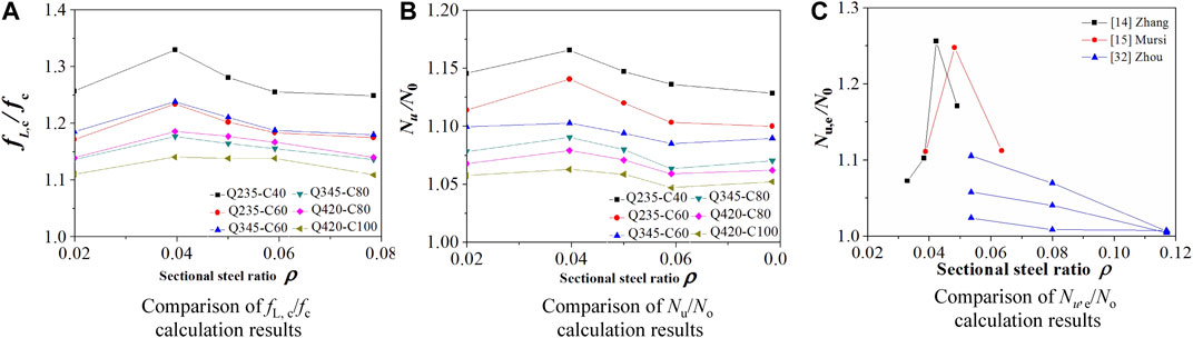
FIGURE 7. Comparison of ratio of calculation results to theoretical values.
Taking square CFST stub columns under axial loading with steel strength of 345 MPa and concrete strength of 60 MPa as an example, the relationship between internal force and axial strain of the example with different steel ratio obtained by FE model is shown in Figure 8.
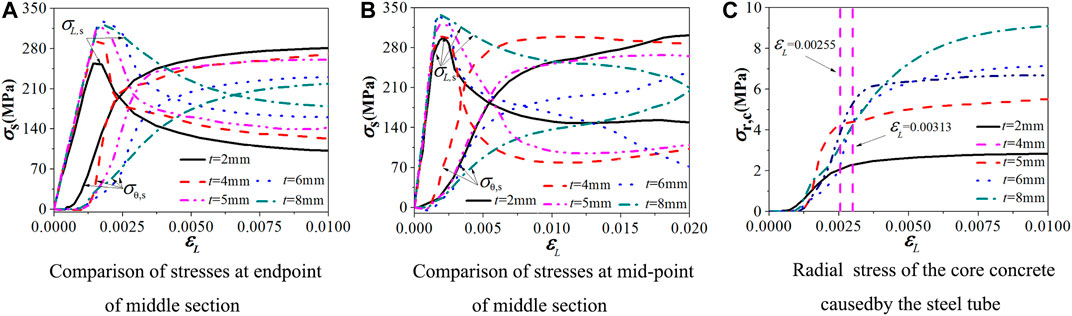
FIGURE 8. Comparisons of mechanical behavior of specimens with different steel ratio.
It can be seen from Figures 8A,B that the axial stress (σL,s) and transverse stress (σθ,s) of the midpoint and endpoint of the middle section of steel tube intersect one another after the steel tube yielding, wherein the axial stress and the transverse stress of the stub columns with the steel ratio of 0.04 is the earliest intersect, followed by stub columns with the steel ratio of 0.02 and 0.05, and finally the stub columns with steel ratios of 0.06 and 0.08, which shows that the stub columns with a steel ratio less than 0.05 example has obvious confinement effect on the core concrete; Refer to the equivalent concrete lateral compression stress concept and calculation method proposed in the reference (Ding et al., 2018). The calculation diagram of core concrete in the limit state is shown in Figure 9. According to the limit equilibrium theory, the lateral force of the concrete subjected to the steel tube (2tσθ,s) is in equilibrium with the lateral restraint force of the steel tube in the core concrete reinforcement zone (σr,cB), that is, the relationship between the transverse stress of the core concrete and the transverse stress of the steel tube is defined as
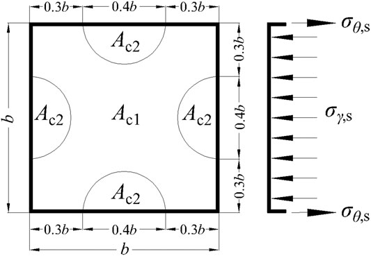
FIGURE 9. Stress zone division of square concrete filled steel tubular columns.
The equivalent radial stress-strain curve of the core concrete with stub columns under different steel ratios is obtained as shown in Figure 8C. It can be seen that the axial strain of the core concrete at the ultimate load-carrying capacity under different steel ratios is 0.00291, 0.00255, 0.00287, 0.00255, and 0.00313, respectively. In the interval of 0.0025–0.0031, the equivalent radial stress of the short column with the steel ratio of 0.04 and 0.05 is the largest. At this time, the confinement effect of the steel tube on the core concrete is greater than that of the remaining stub columns.
In order to study the effect of strength matching between steel tube and concrete on the confinement effect, a thin-wall square CFST stub column with a steel ratio of 0.04 is used as a reference example. fs = 235 MPa is paired with fcu = 40, 60, and 80 MPa in the analysis; fs = 345 MPa is paired with fcu = 60, 80 and, 100 MPa; fs = 420 MPa is paired with fcu = 60, 80, and 100 MPa, and there are nine sets of FE models. Figure 10 compares the axial and transverse stress-strain curves of the steel tube at the end of the section of the square steel tube. It can be seen that the axial stress and the transverse stress of the steel tube strength 235 MPa with the concrete strength 40 MPa, the steel tube strength 345 MPa with the concrete strength 60 MPa stub columns intersect at the earliest. At this time, the confinement effect of the steel tube on the core concrete is better.
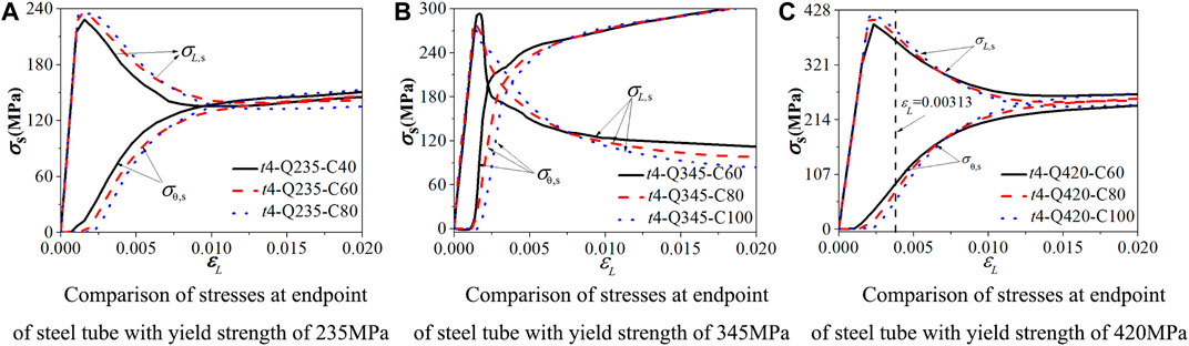
FIGURE 10. Stress-axial strain curves of steel tube among specimens from FE results.
And it can be seen from Figure 10C that when the ultimate load-carrying capacity is reached (i.e., the axial strain is equal to 0.00313), the transverse stress rise rate and the axial stress decrease rate of the examples with the steel yield strength of 420 MPa and compressive cubic concrete strength of 60 MPa are greater than those in other examples. The examples with steel yield strength of 420 MPa and compressive cubic concrete strength of 100 MPa show that the axial stress and the transverse stress of the steel tube intersect at the earliest after the ultimate load-carrying capacity, and the confinement effect is better. Therefore, considering the improvement effect of bearing capacity and ductility, it can play better material properties that the steel tube with the yield strength of 235 MPa is paired with compressive cubic concrete strength of 60 MPa.
The definition of the confinement index (ϕ = fsAs/(fcAc)) was derived from the axial compression test of circular CFST stub columns where only concrete subjected to compression. The confinement index can define the confinement effect of steel tube due to the circular steel tube is uniformly tensioned in the circumferential direction and yielding stress can be achieved when concrete compressed only. At the same time, many experimental results (Ding et al., 2017) show that there was no significant difference in the ultimate load-carrying capacity of the circular CFST stub columns subjected to full-section compression and only concrete compression. So confinement index was also used to define full-section compression of circular CFST stub columns under axial compression, and this definition had since been extended to all types of the CFST stub columns under axial compression. The finite element analysis of the circular CFST stub columns subjected to full-section compression was carried out by Ding (Ding et al., 2019). The results show that the average value of the transverse stress and the yield strength ratio of the circular steel tube at the ultimate load-carrying capacity is 0.55, which did not all play the role of confinement effect; The finite element analysis of the square CFST stub columns subjected to full-section compression was also carried out by Ding (Ding et al., 2019). The results show that the average value of the transverse stress and the yield strength ratio of the square steel tube at the ultimate load-carrying capacity is 0.33, which played a less restrictive role. Therefore, in order to investigate the relationship between the numerical value and the confinement effect of the square steel tube, the author collected the test bearing capacity of 46 sets of square CFST stub columns under axial compression. The variation law of the ratio of Nu,e to nominal ultimate load-carrying capacity N0 with the value of ϕ is shown in Figure 11. It can be seen that there is no clear linear relationship between them, so the confinement index is not accurate to describe the confinement effect of steel tube on concrete. It is more appropriate to define the ratio of the axial pressures of concrete and steel tubes.
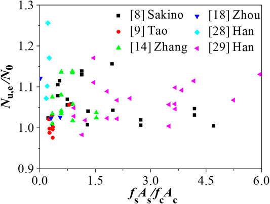
FIGURE 11. Relationship between force ratio and bearing capacity improvement coefficient.
Based on the limited state stress cloud diagram obtained by the FE model, the concrete is divided into the constrained area and the unconstrained area. According to the force balance principle, the calculation formula of the bearing capacity of square CFST stub columns under axial loading is proposed as following (Ding et al., 2019):
where K = 1.2 is the confinement coefficient of square CFST columns.
According to the calculation results of the finite element model, the comparison between the ultimate load-carrying capacity values Nu,fe obtained by the FE model, and the ultimate load-carrying capacity values Nu,c(2) obtained by Eq. 4 is shown in Figure 12. The results show that for short columns with steel ratios of 0.06 and 0.08, the average value of Nu,c (2)/Nu, fe is 0.988 and the discrete value is 0.021. And for short columns with steel ratio ρ = 0.02, 0.04, and 0.05, the average value of Nu,c(2)/Nu,fe is 0.941 and the discrete value is 0.032. The comparison shows that the bearing capacity of the short column with the steel ratio less than 0.05 calculated by the Eq. 4 is too small. Therefore, it is necessary to correct the constraint coefficient of square CFST stub columns with a low steel ratio under axial loading by the same method.
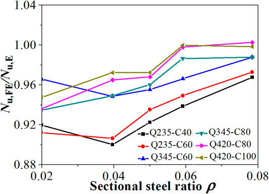
FIGURE 12. Comparison between formula calculation results and FE calculation results.
Figure 13 shows the relationship between the ratio of the axial stress (σL,s) and the yield strength (fs) of the steel tube with the steel ratio less than 0.05 at the endpoint and the midpoint of the middle steel tube with the ultimate strength of the specimen (fsc= Nu/Asc) when the ultimate load-carrying capacity is reached.
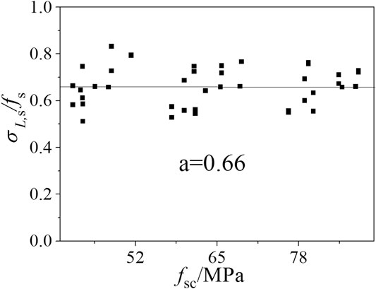
FIGURE 13. Average ratios of axial compressive stresses to yield stresses of the steel tubes.
The average value of the ratio of the axial compressive stress of the square steel tube to the yield strength of the steel tube can be expressed as:
The transverse tensile stress of the square steel tube can be expressed as below in the Von Mises yield criterion.
According to the calculation method of the literature (Ding et al., 2019), the ultimate load-carrying capacity of square steel tubular concrete stub columns with a low steel ratio is obtained as:
where K = 1.3 is the confinement coefficient of the square CFST columns with the steel ratio less than 0.05.
Table 3 lists the values of the coefficient K in different cases. For the 18 short column examples with steel ratios of 0.02, 0.04, and 0.05, the average value of the calculated value of Eq. 7 and the FE calculation is 0.968, and the discrete value is 0.028.

TABLE 3. Relationship between axial (transverse) stress and yield strength of steel tubes.
Table 4 shows the practical calculation formulas for the bearing capacity of square CFST columns under axial loading proposed by other scholars or norms. Table 5 shows the comparison of the test results of the three square CFST columns in this study and the collection of 19 square CFST columns with a steel ratio less than 0.05 and the calculation results of Eq. 7 and other formulas. It can be seen that Eq. 7 provides the most accurate results compared to the experimental value, and the average comparison ratio is 0.960, and the discrete value is 0.046. Comparisons of calculated results of ultimate load-carrying capacity using Eq. 7 (Nu,c(7)) to experimental results (Nu,e) are shown in Figure 14. This demonstrates the accuracy of the proposed Eq. 7 in this study.
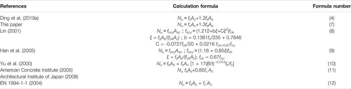
TABLE 4. Practical main calculation formula for bearing capacity of square steel tube concrete.
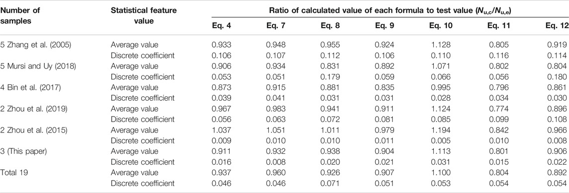
TABLE 5. Comparison of calculation results and experimental results.
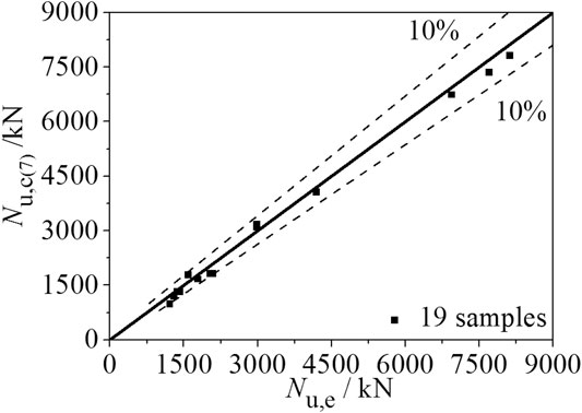
FIGURE 14. Comparisons of calculated results of ultimate load-carrying capacity using Eq. (7) (Nu,c(7)) to experimental results (Nu,e).
In this paper, the mechanical behavior of square CFST columns with a low steel ratio is carried out through experimental and FE analysis. Based on the study, the main conclusions are summarized below:
(1) Based on the experimental results, the stiffness, bearing capacity and ductility coefficient of SCFST columns with low steel ratio under axial loading increase with the increase of steel ratio. The FE model reflects the experimental law, and the calculation results of bearing capacity are in good agreement with the experimental results;
(2) Based on FE analysis, the confinement index ϕ is not accurate to describe the confinement effect of steel tube on concrete. It is more appropriate to express it as the ratio of the axial pressures of concrete and steel tubes. And it’s found that the steel tube of the square CFST column with the steel ratio of 0.04 has the best confinement effect on the concrete. When the practical calculation formula of bearing capacity is used to calculate the square CFST column with the steel ratio below 0.05, the confinement coefficient (K) is more suitable for 1.3.
(3) In the thin-wall square CFST column under axial loading with the same low steel ratio, when the steel tube with the yield strength of 235 MPa is paired with compressive cubic concrete strength of 40MPa, the steel tube with the yield strength of 345 MPa is paired with compressive cubic concrete strength of 60 MPa and the steel tube with the yield strength of 420 MPa is paired with compressive cubic concrete strength of 100 MPa, the steel tube has better confinement effect on concrete.
(4) Based on the experimental results and FE modeling, a practical calculation formula for the ultimate load-carrying capacity of square CFST stub columns with low steel ratio was proposed. The formula calculation results presented in this paper show good agreement with the experimental results. Compared with the existing formulas, the proposed formula has better precision.
The original contributions presented in the study are included in the article/Supplementary Material, further inquiries can be directed to the corresponding author.
LD: Investigation, Formal analysis, Writing- Original draft preparation, Visualization. GY: Writing - Revised Draft, Writing - Review & Editing, Visualization. DF: Conceptualization, Methodology, Supervision. WL: Investigation, Formal analysis. DC: Engineering Guidance, Chart revision. YT: Engineering Guidance, Chart revision. LC: Engineering Guidance, Formula revision. RE: Engineering Guidance, Formula revision.
This research is supported by the National Natural Science Foundation of China (Grant No. 51978664), the Science Fund for Distinguished Young Scholars of Hunan (Grant No. 2019JJ20029) and the Hunan Provincial Innovation Foundation for Postgraduates (Grant No. 150110010).
Author CD was employed by company Hunan Academy of Research Co.Ltd. Author TY was employed by company Hunan Architectural Design Institute Co.Ltd. Author CL was employed by company China Construction Fifth Engineering Division Corp.Ltd. Author ER was employed by company Architectural Design & Research Institute Co.Ltd. of Guangdong Province.
The remaining authors declare that the research was conducted in the absence of any commercial or financial relationships that could be construed as a potential conflict of interest.
Ac, Cross-sectional area of the core concrete; As, Cross-sectional area of the steel tube; Asc, Total area of cross-section; B, Width of the square section; fc, Uniaxial compressive strength of concrete; fL,c, Axial average maximum stress of the core concrete; fcu, Compressive cubic strength of concrete; fs, Yield strength of the steel tube; fsc, Ultimate strength of CFST column; L, Height of specimens; Nu, Axial ultimate load-carrying capacity of thin-walled square CFST stub columns; Nu,e, Ultimate bearing capacity of thin-walled square CFST stub columns from test results; Nu,fe, Ultimate bearing capacity of thin-walled square CFST stub columns from FE results; Nu,c, Ultimate bearing capacity of thin-walled square CFST stub columns from calculation results; Nu,c(2), Ultimate bearing capacity of thin-walled square CFST stub columns from results of Eq. 2; N0, Superimposed bearing capacity of thin-walled square CFST stub columns; t, Wall thickness of the steel tube; σL,c, Axial stress of concrete; σL,s, Axial compressive stress of steel tube; σr,c, Radial concrete stress of the confined area; σθ,s, Tensile transverse stress of steel tube; ε, Axial strain of concrete; εc, Strain corresponding with the peak compressive stress of concrete; εL, Axial strain of columns; ρ, Steel ratio of the steel tube; K, The confinement coefficient of square CFST columns
American Concrete Institute (2005). Building code requirements for reinforced concrete and commentary (ACI318R-05). Detroit, MI, USA: American Concrete Institute Committee.
Architectural Institute of Japan (2008). Recommendations for design and construction of concrete filled steel tubular structures. Tokyo, Japan: Architectural Institute of Japan.
Bin, L. I., Guo, S., and Gao, C. (2017). Experimental research on mechanical behavior of concrete-filled thin-walled stiffened square steel tubular short column under axial load. J. Build. Struc. 275–277, 1049–1057.
Ding, F. X., Lu, D. R., and Bai, Y. (2018). Comparative study of square stirrup-confined concrete-filled steel tubular stub columns under axial loading. Thin-Wall. Struc. 98, 443–453.
Ding, F.-x., Wang, W.-j., Lu, D.-r., and Liu, X.-m. (2020). Study on the behavior of concrete-filled square double-skin steel tubular stub columns under axial loading. Structures 23, 665–676. doi:10.1016/j.istruc.2019.12.008
Ding, F. X., Yin, Y. X., Mao, J. F., Wang, L. P., Yu, Y. J., Luo, L., et al. (2019b). Analytical behaviors of concrete-filled circular stainless steel tubular (CFCSST) stub columns under axial loading. Structures 19, 277–285. doi:10.1016/j.istruc.2019.01.013
Ding, F. X., Yin, Y. X., and Wang, L. P. (2019a). Confinement coefficient of concrete-filled square stainless steel tubular stub columns. Steel Compos. Struct. 30 (4), 337–350.
Ding, F. X., Tan, L., Liu, X. M., and Wang, L. (2017). Behavior of circular thin-walled steel tube confined concrete stub columns. Steel Compos. Struct. 23 (2), 229–238. doi:10.12989/scs.2017.23.2.229
EN 1994-1-1 (2004). EC4 Design of steel and concrete structures (part 1.1 general rules-structural fire design). Eur. Union Per Regul. 118.
GB 50017-2017 (2017). Standard for design of steel structures. Beijing, China: China Architecture and Building PressAvailable at: https://www.chinesestandard.net/PDF.aspx/GB50017-2017 (Accessed December 12, 2017).
GB/T 228.1-2009 (2010). Metallic materials-tensile testing-part 1: method of test at room temperature. Beijing, China: China Standards PressAvailable at: https://www.chinesestandard.net/PDF.aspx/GBT1.1-2009 (Accessed January 1, 2010).
GB/T 50081-2019 (2019). Standard for method of mechanical properties on ordinary concrete. Beijing, China: China Building Industry PressAvailable at: https://www.chinesestandard.net/PDF/English.aspx/GBT50081-2019
Giakoumelis, G., and Lam, D. (2004). Axial capacity of circular concrete-filled tube columns. J. Constr Steel Res. 60 (7), 1049–1068. doi:10.1016/j.jcsr.2003.10.001
Han, L.-H., Yao, G.-H., and Zhao, X.-L. (2005). Tests and calculations for hollow structural steel stub columns filled with self-consolidating concrete. J. Construc. Steel Res. 61 (9), 1241–1269. doi:10.1016/j.jcsr.2005.01.004
Kato, B. (1995). Comprehensive strength and deformation capacity of concrete-filled tubular stub columns. J. Struct. Construc. Eng. 468 (3), 183–191. doi:10.3130/aijs.60.183
Lin, H. (2001). Study on behavior of concrete filled square steel tubes under axial load. China Civil Eng. J.
Lume, G., Rasmussen, K. J. R., and Tao, Z. (2017). Experimental behaviour of high-strength thin-walled concrete filled steel tubular stub columns. Ce/papers 1 (2–3), 1976–1985. doi:10.1002/cepa.242
Mursi, M., and Uy, B. (2018). Strength of concrete filled steel box columns incorporating interaction buckling. J. Struct. Eng. 126 (3), 626–639.
Nie, J., Bai, Y., and Cai, C. S. (2008). New connection system for confined concrete columns and beams. J. Struct. Eng. 134 (12), 1787–1799. doi:10.1061/(asce)0733-9445(2008)134:12(1787)
O shea, M. D., and Bridge, R. O. (2000). Design of circuiar thin-walled concretefilled steel tubes. J. Struct. Eng. ASCE 126 (11), 1295–1303.
Sakino, K., Nakahara, H., Morino, S., and Nishiyama, I. (2004). Behavior of centrally loaded concrete-filled steel-tube short columns. J. Struct. Eng. 130 (2), 180–188. doi:10.1061/(asce)0733-9445(2004)130:2(180)
Shanmugam, N. E., and Lakshmi, B. (2001). State of the art report on steel-concrete composite columns. J. Constr. Steel 57 (10), 1041–1080. doi:10.1016/s0143-974x(01)00021-9
Tao, Z., Han, L.-H., and Wang, D.-Y. (2008). Strength and ductility of stiffened thin-walled hollow steel structural stub columns filled with concrete. Thin Wall. Struct. 46c (10), 1113–1128. doi:10.1016/j.tws.2008.01.007
Tao, Z., Uy, B., Han, L.-H., and Wang, Z.-B. (2009). Analysis and design of concrete-filled stiffened thin-walled steel tubular columns under axial compression. Thin Wall Struct. 47 (12), 1544–1556. doi:10.1016/j.tws.2009.05.006
Uy, B. (2011). “Applications, behaviour, design, research and sustainability of steel and composite structures in Australia,” in Proceedings of the 2011 world congress on advances in structural engineering and mechanics, Seoul, Korea. March 9, 2012. Available at: https://doi.org/10.1260/1369-4332.15.9.1559 (Accessed November 07, 2016).
Wang, S. H., Hu, H. T., Huang, C. S., et al. (2002). Axial load behavior of stiffened concrete-filled steel columns. J. Struct. Eng. 128 (9), 1222–1230.
Yang, W., Cheng, X., Wu, G., Duan, M., and Wang, L. (2019b). Experimental investigations of concrete-filled steel tubular columns confined with high strength steel wire. Adv. Struct. Eng. 22 (13), 2771–2784.
Yang, W., Jiang, C., and Wu, Y. (2019a). Confinement effectiveness of circular concrete-filled steel tubular columns under axial compression. J. Construct. Steel Res. 158 (7), 15–27.
Yu, Y., Lu, X., and Tanaka, K. (2000). Study on concrete-filled square steel tuber with axial load: II analysis. Build. Struct. 30 (2), 43–46.
Zhang, Y., Wang, Q., and Mao, X. (2005). Research on mechanics behavior of stub-column of concrete-filled thin-walled steel tube under axial load. Build. Struct. 35 (1), 22–27.
Zhou, X., Yan, B., and Liu, J. (2015). Behavior of square tubed steel reinforced-concrete columns under eccentric compression. Thin Wall Struct. 91, 129–138. doi:10.1016/j.tws.2015.01.022
Zhou, Z., Gan, D., and Zhou, X. (2019). Improved composite effect of square concrete-filled steel tubes with diagonal binding ribs. J. Struct. Eng. 145 (10), 04019112. doi:10.1061/(asce)st.1943-541x.0002400
Keywords: square CFT stub columns, low steel ratio, restriction effect, practical calculation formula, ABAQUS program 2
Citation: Lu D, Gong Y, Ding F, Wang L, Deng C, Yuan T, Luo C and Ren E (2021) Experimental Study of Square CFST Stub Columns With a Low Steel Ratio Under Axial Loading. Front. Mater. 8:629819. doi: 10.3389/fmats.2021.629819
Received: 16 November 2020; Accepted: 10 February 2021;
Published: 13 April 2021.
Edited by:
Yan-Bo Wang, Tongji University, ChinaReviewed by:
Zehra Canan Girgin, Yıldız Technical University, TurkeyCopyright © 2021 Lu, Gong, Ding, Wang, Deng, Yuan, Luo and Ren. This is an open-access article distributed under the terms of the Creative Commons Attribution License (CC BY). The use, distribution or reproduction in other forums is permitted, provided the original author(s) and the copyright owner(s) are credited and that the original publication in this journal is cited, in accordance with accepted academic practice. No use, distribution or reproduction is permitted which does not comply with these terms.
*Correspondence: Yongzhi Gong, Z3l6Y3N1QGNzdS5lZHUuY24=; Faxing Ding, ZGluZmF4aW5AY3N1LmVkdS5jbg==
Disclaimer: All claims expressed in this article are solely those of the authors and do not necessarily represent those of their affiliated organizations, or those of the publisher, the editors and the reviewers. Any product that may be evaluated in this article or claim that may be made by its manufacturer is not guaranteed or endorsed by the publisher.
Research integrity at Frontiers
Learn more about the work of our research integrity team to safeguard the quality of each article we publish.