
95% of researchers rate our articles as excellent or good
Learn more about the work of our research integrity team to safeguard the quality of each article we publish.
Find out more
ORIGINAL RESEARCH article
Front. Mater. , 25 March 2021
Sec. Structural Materials
Volume 8 - 2021 | https://doi.org/10.3389/fmats.2021.621086
This article is part of the Research Topic Advanced Nuclear Materials for Fission Reactors View all 8 articles
 Peng Wang1
 Yingjie Qiao1
 Wen Qi1
 Shiyu Du1,2
 Zhen Liu1,2
 Fanping Meng2
 Xiaohong Zhang1
 Kun Wang1
 Qiuwu Li1
 Zhaoding Yao1
 Chengying Bai1
 XiaoDong Wang1*
FeCrAl alloy is a promising candidate material for the fourth-generation reactor core cladding material. Adjustment of the Cr content is one of the effective ways to obtain enhanced performance for the FeCrAl alloy. In this work, Fe–xCr–6Al alloy (11 ≤ x ≤ 15) with different Cr content were successfully prepared by hot rolling. When Cr replacement of Fe atoms in Fe–xCr–6Al alloy rises from 11 to 15wt%, the lattice distortion of Fe–xCr–6Al alloy increases, and the mechanical properties and thermal conductivity of the Fe–xCr–6Al alloy are raised. Compared with Al content, Cr content has less effect on Fe–xCr–6Al oxidation resistance.
In recent years, with the potential shortage of traditional energy sources, nuclear power has become increasingly important (Farmer et al., 2014). However, with the occurrence of some well-known nuclear accidents, people have realized that the second and third generation nuclear energy systems in operation would hardly meet the safety requirements and the development of fourth-generation nuclear energy systems is in demand (Guzonas and Novotny, 2014; Yamamoto et al., 2015; Gong et al., 2016). And at present, operating temperature of the typical light water reactor (LWR) in the third-generation nuclear reactor is 285–320°C, while the core outlet pressure and temperature of the supercritical water-cooled reactor (SCWR), which is the fourth-generation nuclear reactor and also adopts light water as the coolant, can be 25MPa and 620–650°C (MacDonald et al., 2005). As the first barrier for nuclear safety protection, the reliability of fuel cladding plays a key role. In the nuclear accident at Fukushima Nuclear Power Plant in Japan in 2011, the Zr alloy cladding was rapidly oxidized under the loss of coolant accident (LOCA) conditions at 1,200°C, resulting in damage to the core and a hydrogen explosion (Pint et al., 2015).
Subsequently, the researchers conducted a series of investigations on the corrosion mechanism of commercial zirconium alloys, and found the corrosion weight gain of Zr–1Nb and Zr–Sn–Nb in LiOH aqueous solution at 360°C/18.6MPa are 0.4–0.8mg/mm2 during 200-days exposure (Chen et al., 2015, 2016, 2018). And the oxidation weight gains of commercial zirconium alloy like Zry-4, D4, M5, E110 and Zirlo in 600°C high temperature water vapor are 2–10mg/cm2h during 45h exposure. But as the oxidation temperature increases, the oxidation weight gains of commercial zirconium alloy like Zry-4, D4, M5, E110 and Zirlo in 1,200°C high temperature water vapor are 50–80mg/cm2h (Steinbrück et al., 2011). Therefore, it is difficult to adopt the current commercial Zr alloys as claddings in the fourth-generation nuclear reactors, which call for novel materials to replace Zircaloy with higher tolerance under extreme conditions. Recently, the FeCrAl ferritic alloy attracts attention due to its excellent oxidation resistance, and quickly become one of the candidate materials for the fourth-generation nuclear energy system cladding (Dryepondt et al., 2018).
The nuclear fuel cladding is not only a protective layer between the nuclear fuel and the coolant, but also provides the necessary structural support for the nuclear fuel. (Chang et al., 2019). For this reason, the desired cladding materials should provide sufficient strength and oxidation resistance to ensure that it can last a long time in the LOCA conditions (Zinkle et al., 2014; Konings et al., 2015; Gamble et al., 2017). For the performance of FeCrAl alloy, researchers have reported plenty of studies on their oxidation resistance (Field et al., 2015; Yamamoto et al., 2015; Aghamiri et al., 2020). the oxidation weight gain of FeCrAl alloy is much lower than this value (Pan et al., 2016; Maeda et al., 2019; Qiao et al., 2020). However, challenge persists for reliability of FeCrAl alloys in a harsh environment, e.g. in a supercritical water-cooled reactor where the operating temperature may exceed 380°C and the enthalpy for the reaction between the nuclear fuel cladding material and supercritical water is increased (Naidin et al., 2009).
As the cladding of nuclear fuel suffers from the internal pressure caused by the swelling, investigations have been performed on the factors affecting the mechanical properties (Yano et al., 2017; Sun et al., 2018; Kim et al., 2019; Yang et al., 2020) as well as the thermal conductivities of the FeCrAl alloy (Niu et al., 2008; Liu et al., 2017). In the meantime, the influence of main element content on thermomechanical performances are also concerned on. He et al. (2018) used industrial pure metals Fe, Cr and Al for vacuum induction smelting, and prepared 25 kg FeCrAl alloy ingots with different Al contents. Their results show that the prepared FeCrAl alloy exists as a body-centered cubic solid solution of α-Fe (Cr, Al) in which Cr and Al are dissolved in Fe. The ferrite phase remains stable before and after the high temperature tensile test. At all temperatures, the peak stress and yield stress increase with the increase of Al content, resulting from Al solid solution strengthening. Additionally, Young’s modulus decreases with the increase of Al content. Qiu et al. (2018) found that the thermal conductivity of C35M and Zr4 alloy is similar, while the specific heat capacity of C35M alloy is higher than that of Zr4 alloy. Field et al. (2015) prepared four FeCrAl alloys with different Cr and Al content added by arc smelting. Then, the FeCrAl alloy samples were prepared by hot forging, hot rolling and heat treatment, which were used for irradiation experiments. It is found that the samples with low Cr content have no brittle fracture phenomenon after irradiated above 7.0 dpa when FeCrAl alloy is irradiated in the LWR operating temperature range. In addition, compared with traditional Zr-based alloys, FeCrAl alloy samples with low Cr content still retain sufficient tensile properties after neutron irradiation. However, when the content of Cr is within the composition range that is difficult to produce α phase (Dryepondt et al., 2018), its influence on the structure and mechanical properties of FeCrAl alloy still needs further study. Furthermore, it was also found Cr in FeCrAl alloy can participate in oxidation reaction at high temperature and affect the oxidation resistance of the cladding material (Niu et al., 2008). Therefore, more investigations are necessary to understand the effect of Cr on the high temperature water vapor oxidation resistance of the FeCrAl alloy, and control the production of its α phase at the same time. Considering the arguments outlined above, we have prepared different Fe–xCr–6Al alloys (11 ≤ x ≤ 15) with 11–15wt% Cr in this work to understand their composition-structure-property-performance relationships. Through analyzing the influence of Cr content on the mechanical properties, thermal performance and oxidation resistance of alloys, the current study may provide technical reference for the development of advanced nuclear energy system materials in future studies.
In this study, five Fe–Cr–Al alloys with different Cr contents were designed, named as Fe-11Cr-6Al, Fe-12Cr-6Al, Fe-13Cr-6Al, Fe–14Cr–6Al and Fe–15Cr–6Al, respectively. The pure Fe [99.50wt% (Weight percent)], pure Cr (99.00wt%) and pure Al (99.60wt%) were used to prepare the Fe–xCr–6Al alloy (11 ≤ x ≤ 15). The Fe–xCr–6Al ingots with weight of 20kg were obtained by vacuum induction melting (VIM) (Song et al., 2018). Then the ingots were homogenized at 1,150°C for 3h, and then hot rolled to 16mm in thickness at 800°C, finally annealed at 1,000°C for 1h. The composition of Fe–Cr–Al alloy ingots were measured by Inductively Coupled Plasma Optical Emission Spectrometer (ICAP-6300) and carbon analyzer (HW2000B). The detection limits for ICAP-6300 and HW2000B are 0.01–99.99 and 0.0001–99.9999wt% and the results are listed in Table 1.
X-ray diffraction (XRD) measurements of Fe–xCr–6Al alloy were performed using a D8 Advance X-ray diffractometer with a Cu-Ka source (λ = 1.540,598Å). Surface morphologies were characterized by a Phenom Pure scanning electron microscope (SEM). Metallographic organization were characterized by a metallographic optical microscope. The HVS-1000A digital microhardness tester was used to test the microhardness of Fe–xCr–6Al alloy. The ES310D density balance was used to test the room temperature density of Fe–xCr–6Al alloy. Compression sample was 10 mm × 10 mm×30mm. Compression tests were conducted using shoulder loading at a crosshead speed of 2mm/min with WDW-100 mechanical testing machine. The engineering stress was calculated by dividing the applied load by the initial cross-sectional area. All compression tests were performed at room temperature.
The oxidation experiments were conducted with reference to ISO 102700 and GBT 13303-1991. Initially, the Al2O3 crucible was roasted at 1,200°C until the weight change was less than 0.0001mg, and the Fe–Cr–Al alloy sample with the size of 20mm × 10mm×3mm was polished to 2,000 mesh and then put into the vacuum atmosphere tube furnace (SLG-1400C) by leaning in the crucible. After the sample was placed stably, the steam evaporator feed pump was turned on and ran for 5min. After the air was discharged from the heating pipe, the heating device was switched to 1,200°C at 20°C/min and then kept for 4h. After cooling to room temperature, the total weight of the crucible and the sample was weighed. The schematic diagram of the experimental device is shown in Figure 1 (Qiao et al., 2020).
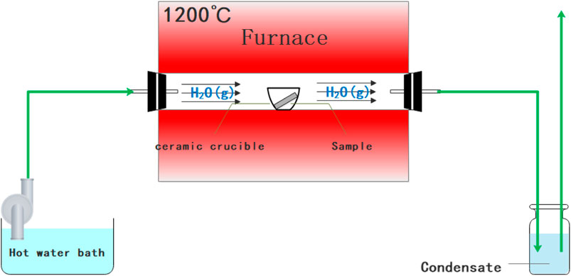
FIGURE 1. Schematic diagram of a controlled environment fireside corrosion test setup (Qiao et al., 2020).
The FeCrAl alloy sample for thermal conductivity test is a cylindrical sheet with a size of Φ12.7mm × 3 mm. The testing equipment is a laser thermal conductivity meter LFA457. The coefficient of thermal expansion (CTE), of Fe–xCr–6Al alloy in the range of 40–400°C is characterized. The test sample size of CTE test is Φ10 mm × 20 mm, and the testing equipment is L75 Platinum Series thermal expansion meter.
The microstructure and macroscopic properties of the alloy are often affected by the types and contents of the elements in the alloy. Therefore, analyzing the influence of elements on the properties of the alloy can help better design the cladding alloy system (Huczkowski et al., 2015; Sun et al., 2017). By analyzing the influence of Cr content on the microstructure morphology, micromechanical properties, oxidation resistance and thermal properties of Fe–xCr–6Al series alloys (11 ≤ x ≤ 15), the relationships of composition-structure-property-performance can be obtained.
[The phase analysis of the rolled Fe–xCr–6Al alloy sample by X-ray diffractometer is shown in Figure 2. The crystal structure of Fe–Cr–Al alloy belongs to the Fe–Cr phase (PDF #54-0331, Space Group Im-3m, No.229). At the same time, its peak width includes Fe, CrFe3, CrFe, Cr2Fe, Cr3Fe and some other Fe–Cr structures. Since the test sample is in a bulk form, the crystal orientation of the samples will affect the absolute strength of XRD which makes the peak intensities varying from one alloy to another, but impact little on peak position. At the same time, the noise value of the XRD in this test is about 3%, which means no observable second phase was formed within the samples and no impurity that can cause notable influence was introduced with the increasing Cr content in the Fe–xCr–6Al alloy.
The lattice constants of Fe–xCr–6Al alloys with different Cr content can be obtained by the Bragg formula written as Eq. 1 (Saowadee et al., 2017). In Eq. 1, d is the interplanar distance of the Fe–xCr–6Al alloys; θ is the angle between the incident X-ray and the corresponding crystal plane; λ is the X-ray wavelength; n is the diffraction order, usually set to 1. Since Fe–xCr–6Al alloys are body-centered cubic, its lattice constant is 2days. The composition-lattice constant curve of the Fe–xCr–6Al alloy {2 0 0} crystal planes, as shown in Figure 3. It is found that the unit cell distorted with the increase of Cr content, and the lattice constant of Fe–xCr–6Al alloy increases. And α-Fe atomic radius is 0.1241nm, α-Cr atomic radius is 0.1249nm. When Cr content in Fe–xCr–6Al alloy increases, the unit cell of the alloy is expanded, making the unit cell size of the Fe–xCr–6Al alloy increase, and leading in the distortion of its crystal structure increase.
Figure 4 shows the as-cast Fe–13Cr–6Al alloy before metallographic corrosion. The surface morphology can be found in good homogeneity and there is no precipitation of carbides or other inclusions, although there are some small pores on the surface of the alloy, which may be produced during the casting process.
Figure 5 shows the grain structure of the columnar crystal region for the as-cast FeCrAl alloy after metallographic surface treatment. With the Cr content of the Fe–xCr–6Al alloy increasing from 11 to 15wt%, the grain size of the columnar crystal region for the as-cast Fe–xCr–6Al alloy fluctuates from 1,000 to 1,500μm. At the same time, it can be found that the micropores on the surface expanded after metallographic surface treatment.
Figure 6 shows the grain size of Fe–xCr–6Al alloy recrystallization annealed at 1,000°C for 60min after metallographic surface treatment. the observation shows that the Fe–xCr–6Al alloy has been completely recrystallized. And When the Cr content of Fe–xCr–6Al alloy varies from 11wt% to 15wt%, the grain size of Fe–xCr–6Al alloy fluctuates from 300 to 550μm.
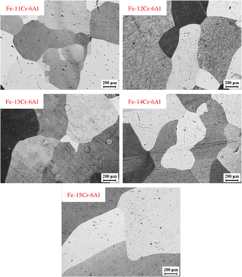
FIGURE 6. Recrystallization and annealing structure of Fe–xCr–6Al alloys with different Cr content after rolling.
Figure 7 shows the density of Fe–xCr–6Al series alloys at room temperature. When the Al content is unchanged and the Cr atoms replace the Fe atoms in the Fe–xCr–6Al alloy with 11wt.%-15wt%, the density of the Fe–xCr–6Al alloy decreases. The relative atomic mass of Cr element is 51.996g/mol, while that of Fe element is 55.845g/mol. Therefore, when the content of Al element remains unchanged, the replacement of Fe atoms in Fe–xCr–6Al alloy with 11–15wt% of Cr atoms will result in a decrease in its density. The density at 350°C is derived from Eqs 2 and 3. And △L is the linear expansion length, L is the original length, β is the coefficient of linear expansion, △T is the temperature difference, ρT is the density at temperature T, M is the mass of Fe–xCr–6Al alloy, and VT is the volume at temperature T, ρ is the density at room temperature.
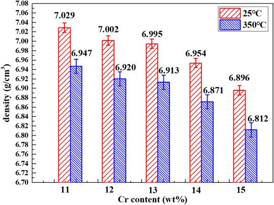
FIGURE 7. Composition-density curves of Fe–xCr–6Al alloys with different Cr content. The density at 350°C is derived from the density of Fe–xCr–6Al alloys at 25°C and coefficient of thermal expansion at 350°C.
The compressibility of FeCrAl cladding material appears to be influenced by the Cr content within the alloy, but the detail remains unclear and requires further study. Figure 9 shows the relationship between the Cr content and the compressive yield strength of the FeCrAl alloy at room temperature. It can be seen from Figure 9 that when the Cr content increases, the compressive yield strength of the Fe–xCr–6Al alloy increases. The deformation mechanism of Fe–xCr–6Al alloy is dominated by the movement of edge dislocations at room temperature (Osetsky et al., 2014; Korchuganov et al., 2018). As the Cr content increases, the movement of the dislocation requires greater energy efficiency, so the compressive performance of the Fe–xCr–6Al alloy is improved.
Figure 10 is the curve on CTE of Fe–xCr–6Al alloy at 350°C. It can be seen from Figure 10 that the CTE of Fe–xCr–6Al alloys show a positive trend with respect to the Cr contents. In order to understand this, simple diatomic models are built in this work. Using DFT method at the level of B3LYP/6-31G(d, p) by Gauss09 software, the relationship between the bond length r and the potential energy (△E) of Fe–Fe, Fe–Cr and Cr–Cr are calculated as shown in Figures 11A–C. The relationship between atomic bond length and relative atomic potential energy increase rate (△E′) (Figure 11D) and the relationship between atomic bond length and relative atomic bond length increase rate (Figure 11E) are established by Figures 11A–C. From Figure 11D, it is found
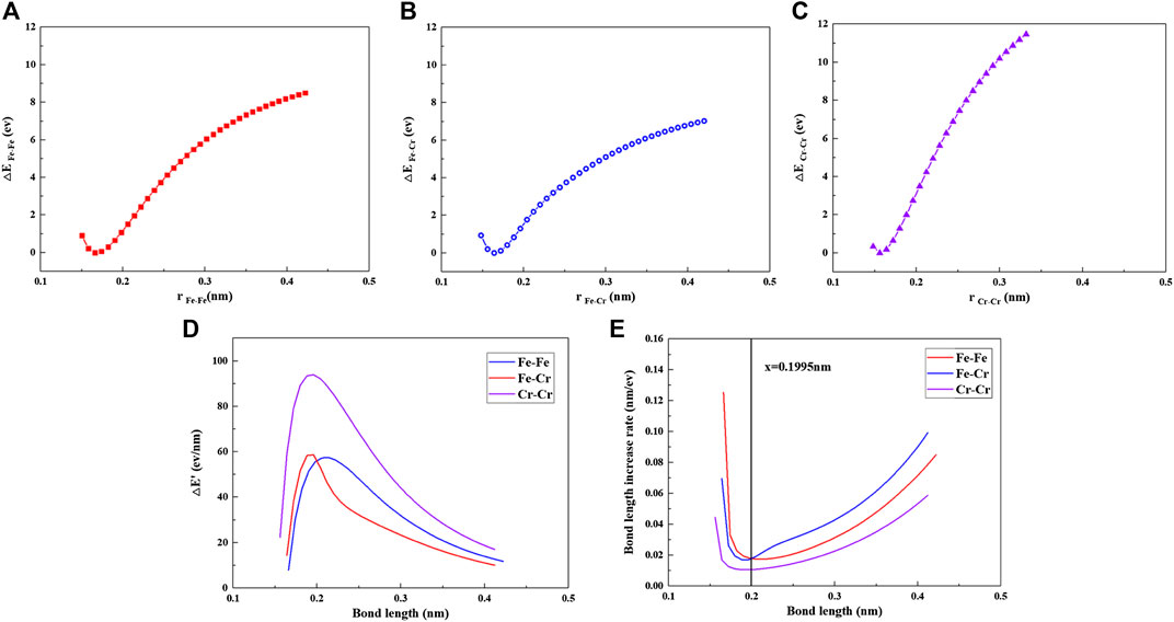
FIGURE 11. (A) rFe-Fe and △EFe–Fe, (B)rFe–Cr and △EFe–Cr, (C)rCr–Cr and △ECr–Cr, (D) bond length and energy increase rate (△E′), and (E) bond length and bond length increase rate.
The specific heat and thermal diffusion coefficient of Fe–xCr–6Al alloy were measured by Differential Scanning Calorimeter, as shown in Figures 12A,Figures 12B. The specific heat and the thermal conductivity of Zircaloy are used as comparison with the data reported by Ott et al. (2014). It can be seen from Figure 12A that when the Cr content in Fe–xCr–6Al increases from 11 to 15wt%, the specific heat of Fe–xCr–6Al alloy decreases first and then increases. When the temperature increases from 25 to 350°C, the specific heat of FeCrAl alloy increases. Compared with zirconium alloy, Fe–xCr–6Al alloy has a higher specific heat capacity.
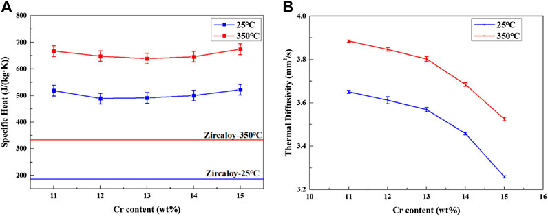
FIGURE 12. The thermal conductivity (A) and thermal diffusivity (B) of Fe–xCr–6Al alloy with different Cr content.
The thermal diffusion coefficient of Fe–xCr–6Al alloy were measured by laser thermal conductivity meter, as shown in Figure 12B. It can be seen from Figure 12B that the thermal diffusivity of Fe–xCr–6Al alloy decreases with the increase of Cr element content. The thermal diffusivity of Fe–11Cr–6Al alloy decreases from 3.65 to 3.26mm2/s at 25°C. At 350°C, the thermal diffusivity of Fe–11Cr–6Al alloy decreases from 3.89 to 3.53mm2/s.
The relationship among solid material thermal conductivity λ, specific heat C, coefficient of thermal expansion α and density ρ is shown in Eq. 4 (Liu et al., 2019):
The specific heat and thermal diffusion coefficient of Fe–xCr–6Al alloy were measured by laser thermal conductivity meter, as shown in Figure 13. It found that the thermal conductivity of Fe–xCr–6Al alloy decreases slightly with the increase of Cr probably because the obstruction of Fe–xCr–6Al alloy’s electron and phonon transport increase with Cr content increase. The thermal conductivity of Fe–11Cr–6Al alloy decreases from 13.3 to 11.7 at 25°C. And at 350°C, the thermal conductivity of Fe–11Cr–6Al alloy decreases from 18.0 to 16.2W/(mK). It is found that the thermal performance of zirconium alloy is slightly better than Fe–xCr–6Al alloy at 25°C, but at 350°C operating temperature, the thermal conductivity of Fe–xCr–6Al alloy is higher than that of zirconium alloy. That means the Fe–xCr–6Al alloy transfers the heat energy of the core to the cooling water more efficiently at operating temperature, which will increase the power generation efficiency of nuclear power plants.
Figure 14 shows the composition-oxidation weight gain curve of Fe–xCr–6Al alloy at room temperature after being oxidized in high temperature water vapor at 1,200°C for 4h. When the Cr content in Fe–xCr–6Al increases from 11 to 14wt%, the oxidation weight gain of Fe–xCr–6Al alloy increases from 0.158mg/cm2 to 0.586mg/cm2 for the oxidation activity of Cr element is higher than that of Fe element. Namely, before forming an effective Al2O3 protective layer, as the content of Cr element increases, the oxidation weight of Fe–xCr–6Al alloy in high temperature water vapor at 1,200°C increases. And then the initial total formation rate of Cr2O3 and Fe2O3 oxides increases with the Cr content increases. At 1,200°C, the Al in the Fe–xCr–6Al alloy has high reducibility, which makes the rate of Al participating in the reduction reaction increase, and the Al2O3 film can be formed faster with the initial formation rate of Cr2O3. When Cr atoms replaced Fe atoms in Fe–xCr–6Al alloy with 14 wt.%-15wt%, the weight gain after oxidation of Fe–xCr–6Al alloy decreased from 0.586 to 0.293mg/cm2. It indicates the oxidation weight gain rate can be greatly reduced when the Al2O3 generated is enough via reducing enough Cr2O3 to coat the Fe–xCr–6Al alloy sample. When the Al2O3 film formed by the reaction is sufficient to cover the Fe–xCr–6Al alloy sample, the anti-corrosion characteristics of the alloy can be observed.
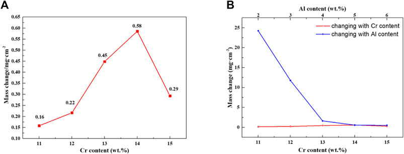
FIGURE 14. Oxidation weight gain of Fe–xCr–6Al alloy with different Cr content after high temperature steam oxidation.
This work mainly studied the influence of different Cr content on the microstructure, mechanical properties, oxidation resistance and thermal properties of Fe–xCr–6Al alloy. When Cr atoms replace Fe atoms in Fe–xCr–6Al alloy from 11 to 15wt%, the changes in properties of Fe–xCr–6Al alloy are summarized as follows:
1. The grain size of the Fe–xCr–6Al alloy varies between 350 and 450μm. And the prepared Fe–xCr–6Al alloy is still a-Fe single-phase structure, which belongs to ferrite, and won’t change with the change of Cr content.
2. The density of Fe–xCr–6Al alloy is slightly reduced, its hardness will increase by 9.7%, and its compressive yield strength will increase from 370 to 394MPa.
3. The oxidation weight gains of the Fe–xCr–6Al alloy obtained by oxidation in a high temperature water vapor environment of 1,200°C for 4h first increased from 0.158 to 0.586mg/cm2 and then decreased to 0.293mg/cm2. This is mainly caused by the combined effect of the increase of the Cr content leading to the increase of the initial oxide generation rate and the substantial reduction of the oxidation rate after the aluminum oxide film completely covers the Fe–xCr–6Al alloy.
4. The thermal expansion coefficient increase, the thermal conductivity and thermal diffusion coefficient of Fe–xCr–6Al alloy decrease, and the specific heat decreases first and then increases.
The original contributions presented in the study are included in the article/Supplementary Material, further inquiries can be directed to the corresponding author.
PW: Methodology, Data Curation, Writing—original draft YQ: Conceptualization, Funding acquisition. WQ: Visualization, Investigation. SD: Writing—Reviewing and Editing, Resources, Software. ZL: Resources, Software. FM: Resources. XZ: Writing–Reviewing and Editing. KW: Resources, Investigation. QL: Resources. ZY: Resources. CB: Writing—Reviewing and Editing. XW: Supervision, Project administration.
The authors would like to express thanks to the financial support from the National Key Research and Development Program of China (Nos. 2016YFB0700100, 2016YFB0700104, and 2019YFB1901003), Zhejiang Province Key Research and Development Program (No. 2019C01060), National Natural Science Foundation of China (Grant No. 21875271), the project of the key technology for virtue reactors from NPIC, Aviation power fund (6141B090571), Heilongjiang Science and Technology Plan Project (GX17A012) and the Fundamental Research Funds for the Central Universities (3072020CF1001) and the Fund of Science and Technology on Reactor Fuel and Materials Laboratory (6142A06190208) and Key Laboratory of Superlight Materials and Surface Technology (Harbin Engineering University).
The authors declare that the research was conducted in the absence of any commercial or financial relationships that could be construed as a potential conflict of interest.
Aghamiri, S. M. S., Sowa, T., Ukai, S., Oono, N., Sakamoto, K., and Yamashita, S. (2020). Microstructure and texture evolution and ring-tensile properties of recrystallized FeCrAl ODS cladding tubes. Mater. Sci. Eng. A. 771, 138636. doi:10.1016/j.msea.2019.138636
Chang, K., Meng, F., Ge, F., Zhao, G., Du, S., and Huang, F. (2019). Theory-guided bottom-up design of the FeCrAl alloys as accident tolerant fuel cladding materials. J. Nucl. Mater. 516, 63–72. doi:10.1016/j.jnucmat.2019.01.002
Chen, L., Li, J., Zhang, Y., Zhang, L. C., Lu, W., Zhang, L., et al. (2015). Effects of alloyed Si on the autoclave corrosion performance and periodic corrosion kinetics in Zr–Sn–Nb–Fe–O alloys. Corros. Sci. 100, 651–662. doi:10.1016/j.corsci.2015.08.043
Chen, L. Y., Shen, P., Zhang, L., Lu, S., Chai, L., Yang, Z., et al. (2018). Corrosion behavior of non-equilibrium Zr–Sn–Nb–Fe–Cu–O alloys in high-temperature 0.01 M LiOH aqueous solution and degradation of the surface oxide films. Corros. Sci. 136, 221–230. doi:10.1016/j.corsci.2018.03.012
Chen, L., Zeng, Q., Li, J., Lu, J., Zhang, Y., Zhang, L. C., et al. (2016). Effect of microstructure on corrosion behavior of a Zr–Sn–Nb–Fe–Cu–O alloy. Mater. Des. 92, 888–896. doi:10.1016/j.matdes.2015.12.067
Dryepondt, S., Unocic, K. A., Hoelzer, D. T., Massey, C. P., and Pint, B. A. (2018). Development of low-Cr ODS FeCrAl alloys for accident-tolerant fuel cladding. J. Nucl. Mater. 501, 59–71. doi:10.1016/j.jnucmat.2017.12.035
Farmer, M. T., Leibowitz, L., Terrani, K. A., and Robb, K. R. (2014). Scoping assessments of ATF impact on late-stage accident progression including molten core–concrete interaction. J. Nucl. Mater. 448, 534–540. doi:10.1016/j.jnucmat.2013.12.022
Field, K. G., Hu, X., Littrell, K. C., Yamamoto, Y., and Snead, L. L. (2015). Radiation tolerance of neutron-irradiated model Fe–Cr–Al alloys. J. Nucl. Mater. 465, 746–755. doi:10.1016/j.jnucmat.2015.06.023
Gamble, K. A., Barani, T., Pizzocri, D., Hales, J. D., Terrani, K. A., and Pastore, G. (2017). An investigation of FeCrAl cladding behavior under normal operating and loss of coolant conditions. J. Nucl. Mater. 491, 55–66. doi:10.1016/j.jnucmat.2017.04.039
Gong, X., Li, R., Sun, M., Ren, Q., Liu, T., and Short, M. P. (2016). Opportunities for the LWR ATF materials development program to contribute to the LBE-cooled ADS materials qualification program. J. Nucl. Mater. 482, 218–228. doi:10.1016/j.jnucmat.2016.10.012
Guzonas, D., and Novotny, R. (2014). Supercritical water-cooled reactor materials - summary of research and open issues. Prog. Nucl. Energ. 77, 361–372. doi:10.1016/j.pnucene.2014.02.008
He, Y., Liu, J., Qiu, S., Deng, Z., Yang, Y., and McLean, A. (2018). Microstructure and high temperature mechanical properties of as-cast FeCrAl alloys. Mater. Sci. Eng. A. 726, 56–63. doi:10.1016/j.msea.2018.04.039
Huczkowski, P., Gopalakrishnan, S. G., Nowak, W., Hattendorf, H., Iskandar, R., Mayer, J., et al. (2015). Effect of Zr content on the morphology and emissivity of surface oxide scales on FeCrAlY alloys. Adv. Eng. Mater. 18, 711–720. doi:10.1002/adem.201500439
Kim, H., Obulan Subramanian, G., Kim, C., Jang, H., and Jang, C. (2019). 400 °C aging embrittlement of FeCrAl alloys: microstructure and fracture behavior. Mater. Sci. Eng. A. 743, 159–167. doi:10.1016/j.msea.2018.11.084
Konings, R. J. M., Wiss, T., and Beneš, O. (2015). Predicting material release during a nuclear reactor accident. Nat. Mater. 14, 247–252. doi:10.1038/nmat4224
Korchuganov, A. V., Zolnikov, K. P., and Kryzhevich, D. S. (2018). Simulation of interaction of edge dislocations with radiation defects in Fe–10Cr alloy. J. Phys. Conf. Ser. 1115, 4–9. doi:10.1088/1742-6596/1115/5/052032
Liu, M., Brown, N. R., Terrani, K. A., Ali, A. F., Blandford, E. D., and Wachs, D. M. (2017). Potential impact of accident tolerant fuel cladding critical heat flux characteristics on the high temperature phase of reactivity initiated accidents. Ann. Nucl. Energ. 110, 48–62. doi:10.1016/j.anucene.2017.06.016
Liu, Y. F., Jia, X. J., Qiao, X. G., Xu, S. W., and Zheng, M. Y. (2019). Effect of La content on microstructure , thermal conductivity and mechanical properties of Mg e 4Al magnesium alloys. J. Alloys Compd. 806, 114. doi:10.1016/j.jallcom.2019.07.267
MacDonald, P., Buongiorno, J., Sterbentz, J., Davis, C., Witt, R., Was, Gary., et al. (2005). Feasibility study of supercritical light water cooled fast reactors for actinide burning and electric power production. Berlin: Springer. doi:10.2172/835712
Maeda, T., Ukai, S., Hayashi, S., Oono, N., Shizukawa, Y., and Sakamoto, K. (2019). Effects of zirconium and oxygen on the oxidation of FeCrAl-ODS alloys under air and steam conditions up to 1500 °C. J. Nucl. Mater. 516, 317–326. doi:10.1016/j.jnucmat.2019.01.041
Naidin, M., Mokry, S., Baig, F., Gospodinov, Y., Zirn, U., Pioro, I., et al. (2009). Thermal-design options for pressure-channel SCWRs with cogeneration of hydrogen. J. Eng. Gas Turbines Power 131, 133. doi:10.1115/1.2983016
Niu, Y., Wang, S., Gao, F., Zhang, Z. G., and Gesmundo, F. (2008). The nature of the third-element effect in the oxidation of Fe–xCr–3 at% Al alloys in 1 atm O2 at 1,000°C. Corros. Sci. 50, 345–356. doi:10.1016/j.corsci.2007.06.019
Osetsky, Y., Khorgolkhuu, O., Samolyuk, G., Nicholson, D., Stoller, R., and Stocks, M. B. T.-A. M. M. (2014). The interaction of Cr and Ni solute atoms with core of screw and edge dislocation in bcc Fe. New York, NY: American Physical Society.
Ott, L. J., Robb, K. R., and Wang, D. (2014). Preliminary assessment of accident-tolerant fuels on LWR performance during normal operation and under DB and BDB accident conditions. J. Nucl. Mater. 448, 520–533. doi:10.1016/j.jnucmat.2013.09.052
Pan, D., Zhang, R., Wang, H., Lu, C., and Liu, Y. (2016). Formation and stability of oxide layer in FeCrAl fuel cladding material under high-temperature steam. J. Alloys Compd. 684, 549–555. doi:10.1016/j.jallcom.2016.05.145
Pint, B. A., Unocic, K. A., and Terrani, K. A. (2015). Effect of steam on high temperature oxidation behaviour of alumina-forming alloys. Mater. High Temp. 32, 28–35. doi:10.1179/0960340914Z.00000000058
Qiao, Y., Wang, P., Qi, W., Du, S., Liu, Z., Meng, F., et al. (2020). Mechanism of Al on FeCrAl steam oxidation behavior and molecular dynamics simulations. J. Alloys Compd. 828, 33–39. doi:10.1016/j.jallcom.2020.154310
Qiu, B., Wu, Y., Deng, Y., He, Y., Liu, T., Su, G. H., et al. (2018). A comparative study on preliminary performance evaluation of ATFs under normal and accident conditions with FRAP-ATF code. Prog. Nucl. Energ. 105, 51–60. doi:10.1016/j.pnucene.2017.12.010
Saowadee, N., Agersted, K., and Bowen, J. R. (2017). Lattice constant measurement from electron backscatter diffraction patterns. J. Microsc. 266, 200–210. doi:10.1111/jmi.12529
Song, P., Morrall, D., Zhang, Z., Yabuuchi, K., and Kimura, A. (2018). Radiation response of ODS ferritic steels with different oxide particles under ion-irradiation at 550°C. J. Nucl. Mater. 502, 76–85. doi:10.1016/j.jnucmat.2018.02.007
Steinbrück, M., Vér, N., and Gro?E, M. (2011). Oxidation of advanced zirconium cladding alloys in steam at temperatures in the range of 600–1200°C. Oxid. Met. 76, 215–232. doi:10.1007/s11085-011-9249-3
Sun, Z., Bei, H., and Yamamoto, Y. (2017). Microstructural control of FeCrAl alloys using Mo and Nb additions. Mater. Charact. 132, 126–131. doi:10.1016/j.matchar.2017.08.008
Sun, Z., Edmondson, P. D., and Yamamoto, Y. (2018). Effects of Laves phase particles on recovery and recrystallization behaviors of Nb-containing FeCrAl alloys. Acta Mater. 144, 716–727. doi:10.1016/j.actamat.2017.11.027
Yamamoto, Y., Pint, B. A., Terrani, K. A., Field, K. G., Yang, Y., and Snead, L. L. (2015). Development and property evaluation of nuclear grade wrought FeCrAl fuel cladding for light water reactors. J. Nucl. Mater. 467, 703–716. doi:10.1016/j.jnucmat.2015.10.019
Yang, Z., Wang, Z. X., Xia, C. H., Ouyang, M. H., Peng, J. C., Zhang, H. W., et al. (2020). Aluminum suppression of α′ precipitate in model Fe–Cr–Al alloys during long-term aging at 475°C. Mater. Sci. Eng. A. 772, 138714. doi:10.1016/j.msea.2019.138714
Yano, Y., Tanno, T., Oka, H., Ohtsuka, S., Inoue, T., Kato, S., et al. (2017). Ultra-high temperature tensile properties of ODS steel claddings under severe accident conditions. J. Nucl. Mater. 487, 229–237. doi:10.1016/j.jnucmat.2017.02.021
Keywords: FeCrAl alloy, thermal performance, mechanical behavior, high-temperature steam oxidation, micro structure
Citation: Wang P, Qiao Y, Qi W, Du S, Liu Z, Meng F, Zhang X, Wang K, Li Q, Yao Z, Bai C and Wang X (2021) Preparation and Properties Study of Cr on FeCrAl Cladding Materials. Front. Mater. 8:621086. doi: 10.3389/fmats.2021.621086
Received: 25 October 2020; Accepted: 08 February 2021;
Published: 25 March 2021.
Edited by:
Liqiang Wang, Shanghai Jiao Tong University, ChinaReviewed by:
Liang-Yu Chen, Jiangsu University of Science and Technology, ChinaCopyright © 2021 Wang, Qiao, Qi, Du, Liu, Meng, Zhang, Wang, Li, Yao, Bai and Wang. This is an open-access article distributed under the terms of the Creative Commons Attribution License (CC BY). The use, distribution or reproduction in other forums is permitted, provided the original author(s) and the copyright owner(s) are credited and that the original publication in this journal is cited, in accordance with accepted academic practice. No use, distribution or reproduction is permitted which does not comply with these terms.
*Correspondence: XiaoDong Wang, d2FuZ3hpYW9kb25nQGhyYmV1LmVkdS5jbg==
Disclaimer: All claims expressed in this article are solely those of the authors and do not necessarily represent those of their affiliated organizations, or those of the publisher, the editors and the reviewers. Any product that may be evaluated in this article or claim that may be made by its manufacturer is not guaranteed or endorsed by the publisher.
Research integrity at Frontiers

Learn more about the work of our research integrity team to safeguard the quality of each article we publish.