 Nengmei Deng1
 Jun Zhao
95% of researchers rate our articles as excellent or good
Learn more about the work of our research integrity team to safeguard the quality of each article we publish.
Find out more
ORIGINAL RESEARCH article
Front. Mater. , 16 February 2021
Sec. Structural Materials
Volume 7 - 2020 | https://doi.org/10.3389/fmats.2020.580938
This article is part of the Research Topic 2021 Retrospective: Structural Materials View all 13 articles
Taking the brazing mechanism of alumina ceramics and kovar alloys as the main research object, based on the molybdenum–manganese metallization method, the influence of the direct and indirect brazing processes on the morphology of the final connected layer is explored. Combined with SEM, EDS, the microscopic morphology, and hermeticity affecting the final ceramic–metal composite component is discussed. Finally, through the indirect brazing process, various ceramic–metal composite joints with good airtightness satisfying the requirements were prepared.
With the depletion of conventional energy, nuclear energy has become an important energy source, and nuclear power has also become an important part of the power industry. Climate change is becoming more pessimistic, and nuclear power is a clean energy. Improving the nuclear power industry is an important approach for world energy development. It meets the growing energy needs of industrial and agricultural production and ensures social stability and harmony (Nehrenheim, 2018; Ul’yanin et al., 2018; ZohuriB, 2019).
However, in the process of nuclear power development, many key technologies, including sealing and connecting technology between ceramics and metals, still need to be developed. Nowadays, electrical penetration is mainly made of polymer as a sealing material, but the polymer has poor high-temperature and radiation resistance, low air tightness, and a short working life. Since the late 1930s, the process of joining ceramics with metals or other materials has steadily advanced. Similar to the connection process between other materials, the connection process between ceramics and other materials is initially more of an art than a science, and the development of proprietary properties in this field has exacerbated this situation. After World War II, Pulfrich (Telefunken) and Vatter (Siemens and Halske, A.G.) achieved the metallization of ceramic to produce a surface that can be wetted by the brazing alloy in subsequent joining operations. Also, a large number of patents on metallization and joining processes were issued to Pulfrich, Vatter, or the company that employed them. Some of these patents are most prominently listed in reference (Clarke et al., 1965).
Subsequently, the sealing and connection technology between ceramics and metals has become more and more important. Due to the use of ceramics as a structural material has broadened its scope of application for the future. For example, when the first space station was established in outer space, the ceramic and metal connectors played a key role in the construction and operation of the first space station. Nuclear and solar energy equipment have been used to provide energy. Ceramic and metal connectors have been used in these devices to convert nuclear and solar energy into electricity. Likewise, a ceramic coating can be used to provide the required firing frequency to control and maintain the proper temperature level inside the space station structure. The performance of spacecraft today is often dependent on the strength provided by ceramic–metal joints, corrosion resistance, and the ability to protect from high temperatures. The main methods to realize permanent sealing between metal parts and ceramic components are hot pressing connection (Berndt et al., 1985), gradient powder connection (Pattee et al., 1968; Giraldez and Horner, 1994), air pressure connection, active metal brazing (Erdemir et al., 2011; Walker et al., 2011), electron beam welding (Solfest and Strangman, 1989), glass solder (Sandhage et al., 1996), ceramic brazing (Nascimento et al., 2003), in situ ceramic sintering (Yoshimura and Suchanek, 1997), and in situ glass crystallization (Jain, 2004).
In this work, the connection between alumina ceramic and Kovar alloy is achieved by active brazing. The main research contents are as follows: Vacuum brazing of alumina ceramics and Kovar alloys was carried out using commercial Ag-Cu-Ti brazing filler metal. The effect of interface structure and process parameters on interface morphology was further analyzed, and the sealing mechanism of interface formation was clarified. The airtightness of the alumina ceramic and the Kovar alloy sealing joint is tested, the influencing factors are analyzed, and the optimum process conditions are preferred. By comparing the presence or absence of a molybdenum–manganese metallization layer, the alumina ceramic and Kovar alloy were sealed to explore the effect of the molybdenum–manganese metallization layer on the sealing effect, explore effective sealing, reduce the defective rate, and save production costs (Tomlinson, 1986; Aita, 1992; Mulpuri and Sarin, 1996; Choy, 2003; Li et al., 2008; Fernie et al., 2009).
Alumina ceramics do not have a molybdenum–manganese metallization layer during the direct brazing process. The brazing material is a silver–copper–titanium solder paste:
First, separately clean 95% alumina ceramic and Kovar.
Second, for parts assembly, first clean the ceramic tube and Kovar in an ultrasonic cleaning machine for 30 min and then soak in the cleaning solution at 70–80°C for 10 min. Then the ceramic tube and Kovar were washed with distilled water 3–5 times and then washed with absolute ethanol. Finally, the cleaned ceramic and Kovar alloy were dried in an oven at 120°C; then, the silver copper wire was cleaned with an alcohol swab, wound in a circle with clean tweezers, and then fixed on the weld. Kovar was placed on ceramic tiles coated with silver–copper solder and was ready for sintering after being fixed and placed in a graphite jig.
Third, in the ceramic–metal brazing process, the metallized alumina ceramic tube prepared in step 2 is assembled with nickel-plated Kovar alloy and silver–copper solder and then placed in a dedicated graphite mold. Then the assembled sample is brazed and sealed at a temperature of 10−3–10–4 Pa and 750–900°C for 2–5 min.
Fourth, in the performance test, the insulation and airtightness of the resulting seals were examined separately.
For the indirect brazing process route, the selected metallized alumina ceramic and Kovar alloy are brazed and sealed. The selected brazing material is silver–copper brazing wire. The rest of the specific steps are similar to the A process (Véchembre and Fox, 2001; Ionkin et al., 2011).
For the indirect brazing process route, the selected metallized alumina ceramic and Kovar alloy are brazed and sealed. The selected brazing material is silver–copper brazing wire. The rest of the specific steps are similar to the A process (Véchembre and Fox, 2001; Ionkin et al., 2011).
The brazing experiment is carried out in a vacuum brazing furnace. The device is mainly composed of vacuum, heating, digital display, recording, and control systems. It can provide an ultimate vacuum of 7 × 10⁻⁴ Pa and a maximum heating of 1,600°C. These performance parameters are sufficient to meet the experimental requirements of this topic.
Before the experiment, the surface oxide film of Kovar was removed with 400#, 800#, and 1000# sandpaper and cleaned with deionized water and acetone, respectively. The alumina ceramic surface was cleaned with ethanol and acetone, respectively. Assemble the process airtight specimens as shown in Figure 1. The diameter and wall thickness of the alumina tube was 2 and 0.1 mm, and the size of the Kovar alloy was 3 mm.
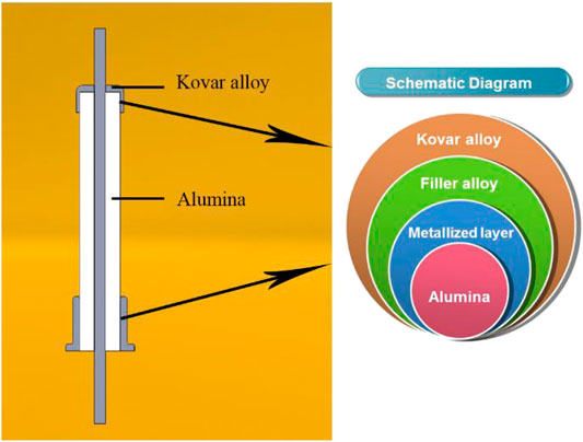
FIGURE 1. The structure diagram of seal tightness test assembly.
The brazing process curve used is shown in Figure 2, where t is the holding time. Considering the ceramic part and the Kovar alloy member easily generate large residual stress in the joint during sealing, the ceramic framework is also very sensitive to stress concentration, so a smaller cooling rate is used to reduce the residual stress in the joint.
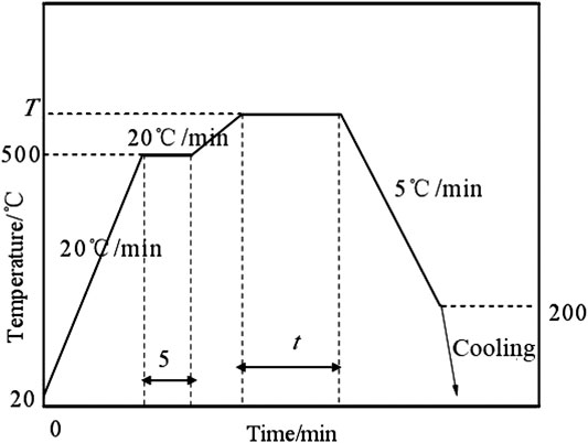
FIGURE 2. The technology curve of brazing experiments with Ag-Cu-Ti solder.
Selecting commercial silver–copper–titanium wire and alumina ceramics with a molybdenum–manganese layer (nickel-plated) as experimental materials, the aluminum oxide ceramic/molybdenum–manganese metallization layer was prepared by a sealing process with a sealing temperature of 780°C and a holding time of 2 min (Huh et al., 2011).
Figure 3 is an SEM image of the interface morphology of the alumina ceramic/molybdenum manganese layer (nickel plated)/binder. From Figure 3A, it can be seen that there is a significant molybdenum–manganese metallization layer between the solder and the alumina ceramic. Figure 3B indicates that the thickness of the molybdenum–manganese layer is about 20 microns. From Figure 3C, we can see that the wettability between the molybdenum–manganese metallization layer and the solder is better. The dark and irregular long bands in the solder layer are silver–copper eutectic structures. Figure 3D shows the distribution of elements enriched at the interface layer. In order to further clarify the product composition at the interface, the distribution of some elements was selected (Khanna, 2011).
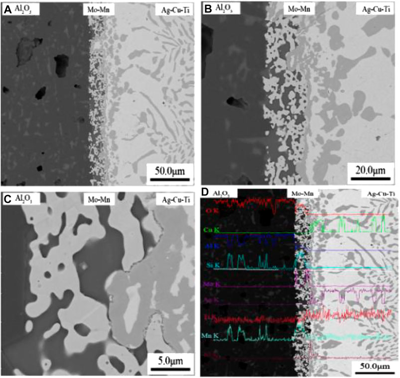
FIGURE 3. (A–D) The interface morphologies of alumina ceramic/solder (780°C/2 min).
Figure 4 presents that, in the position where the active titanium element is enriched in the molybdenum–manganese metallization layer, other elements begin to enrich at corresponding positions, and it can be seen that the titanium element is very active and has a wide distribution range.
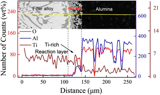
FIGURE 4. The element distribution of O-Al-Ti on the interface microstructure (780°C/2 min).
From Figure 5, it can be seen that the molybdenum–manganese metallurgy layer has started to migrate into the interior of the alumina ceramics, and a complex reaction has occurred with other glass-phase materials in the alumina. Based on the above analysis, it is further proven that the MnO·Al2O3 spinel produced by the reaction of manganese oxide and aluminum oxide in the molybdenum–manganese layer contributes to sealing, and other manganese oxides also react with silica and other oxides in alumina ceramics. MnO·SiO2 and other materials are also helpful for sealing (Chien et al., 2008).
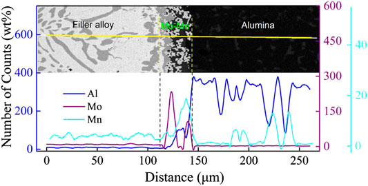
FIGURE 5. The element distribution of Al-Mo-Mn on interface microstructure (780°C/2 min).
Figure 6 shows the SEM photos and elemental distribution profiles of the interface morphology of alumina ceramic/brazing/cobalt alloys. As shown in Figure 6C, it can be clearly observed that the solder and kovar layers have obvious reaction intermediates. The irregular dark banded product in the solder layer is a silver–copper eutectic structure. To further investigate the reactions occurring at the interface, a representative element is selected to analyze the complex reactions at the interface. As shown in Figure 7, there is no significant migration of aluminum, and the active element, titanium, is relatively evenly distributed throughout the interfacial structure with a wide distribution depth. At the same time as shown in Figure 8, a complex chemical reaction occurs between the elements in the solder layer and the elements in the Kovar alloy. Based on the analysis of their relative contents in the energy spectrum, it can be speculated that they are in the interface between the two. The TiFe2, TiNi3 intermetallic layer was formed (Vinod, 2013).
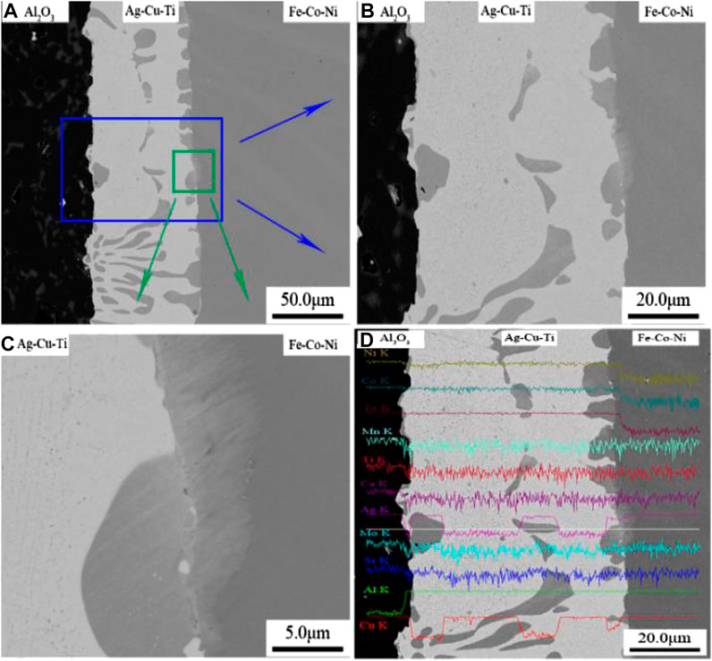
FIGURE 6. (A–D) The interface morphologies of alumina ceramic/solder/Kovar alloy (780°C/2 min).
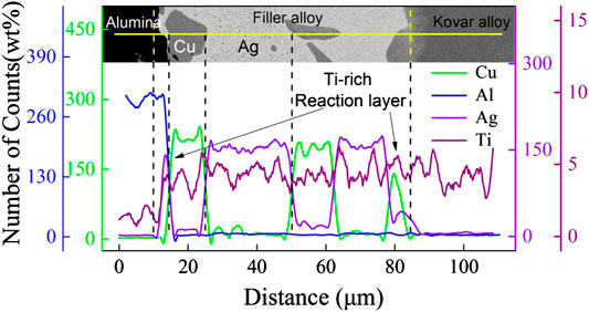
FIGURE 7. The element distribution of Cu-Al-Ag-Tion interface microstructure (780°C/2 min).
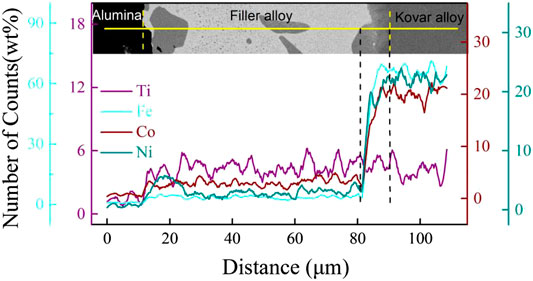
FIGURE 8. The element distribution of Ti-Fe-Co-Nion interface microstructure (780°C/2 min).
The commercial silver–titanium–titanium solder paste and nonmetallized alumina ceramics were selected as the experimental materials. The interface morphology of alumina ceramic/solder layer/Kovar alloy layer was prepared at a sealing temperature of 900°C and a holding time of 2 min.
Figure 9 shows the alumina ceramic/braze/Kovar alloy interface topography. As can be seen from the figure, there are significant microcracks in the solder layer, the wettability at the ceramic interface is poor, the wetting effect with the kovar alloy layer is also not good, and no obvious reaction interface layer is observed. At the same time, the solder layer itself fails to form a dense connection layer, which directly leads to a lower sealing performance of the sealing joint and a greater leakage rate.
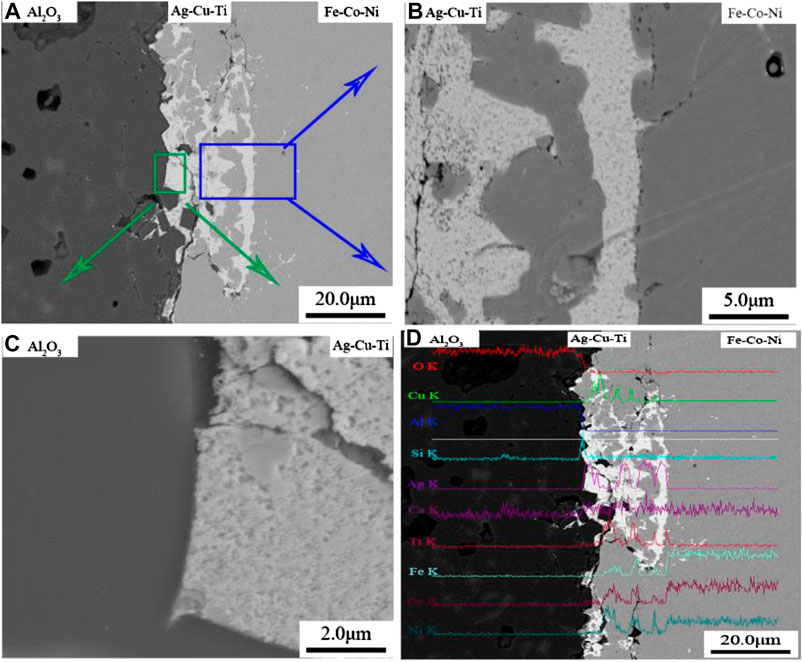
FIGURE 9. The interface morphologies of alumina ceramic/solder/Kovar alloy (900°C/2 min).
Figure 10 shows the results of the energy spectrum analysis of the element at the interface of the joint after direct brazing process conditions. From the figure, it can be seen that there is no change in the oxygen and aluminum elements at the location where the active element titanium is enriched, indicating that the two elements do not react with the active element. In addition, the active elements are mainly concentrated on the solder layer and cannot fully migrate inside the Kovar alloy layer and the alumina ceramics. This shows that, under the direct soldering process conditions, the solder paste of this type fails to fully match the ceramic and Kovar alloy interface. Wet and chemical reactions occur at the interface. At the same time, combined with the results of the elemental distribution shown in Figure 11, in the enriched position of the titanium element, the three main constituent elements in the Kovar alloy layer undergo a complex chemical reaction of iron, cobalt, nickel, and titanium elements and are enriched in the titanium element. Synchronous enrichment occurs in the location. It is further proved that the wettability of the solder layer and Kovar alloy is significantly better than that of the alumina ceramic layer. According to the distribution of elemental content, TiFe2, and TiNi3 intermetallic compound layers exist at the reaction interface.
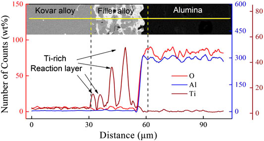
FIGURE 10. The element distribution of O-Al-Ti (900°C/2 min).
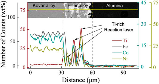
FIGURE 11. The element distribution of Ti-Fe-Co-Ni (900°C/2 min).
Table 1 shows the hermeticity and insulation of the ceramic metal seal joints under the two brazing conditions.

TABLE 1. The hermetic and insulating results of the joint.
Based on the above analysis and experimental data, the ceramic metal sealed joints prepared by the indirect brazing process show excellent performance indicators.
During direct and indirect braze welding, the joints were tested for hermeticity, insulation, and other properties. A well-formed seal was prepared. First, the presence of the molybdenum–manganese metallization layer improves the hermeticity of the sealing structure, which is beneficial to the wetting of the solder layer and the ceramic and, thus, achieves effective sealing with the Kovar alloy layer. Then, the active element titanium in the sealing process and the Kovar alloy in the iron and nickel elements react to generate the TiFe2, TiNi3 intermetallic compound layer, which is conducive to achieving the formation of the seal. Last, the leakage rate of ceramic metal sealed joints prepared under indirect brazing process conditions is <8.0 × 10⁻⁹ Pa m3/s, insulation resistance >2.6 × 10¹⁰ Ω. The research promotes the sealing connection technology between ceramic and metal, which can be applied in the construction of nuclear power plants.
The original contributions presented in the study are included in the article/Supplementary Material, further inquiries can be directed to the corresponding author/s.
Conceptualization, methodology, formal analysis, data curation and writing, J.Z.; Measurement, ZZ.
Funded by Longshan academic talent research supporting program of SWUST (NO. 18lzxt03; NO. 18zx309); Southwest University of Science and Technology Natural Science Foundation (NO. 18zx7125; Fundamental Science on Nuclear Wastes and Environmental Safety Laboratory (NO. 18kfhk02); Shock and Vibration of Engineering Materials and Structures Key Laboratory of Sichuan Province (NO. 18kfgk06).
The authors declare that the research was conducted in the absence of any commercial or financial relationships that could be construed as a potential conflict of interest.
Aita, C. R. (1992). Phase maps for sputter deposited refractory metal oxide ceramic coatings: review of niobium oxide, yttrium oxide, and zirconium oxide growth. Mater. Sci. Technol. 8 (8), 666–672. doi:10.1179/mst.1992.8.8.666
Berndt, D., Neidig, A., Wahl, G., and Wittmer, M. (1985). Method of direct bonding copper foils to oxide-ceramic substrates. U.S. Patent 4,505,418[P].
Chien, C.-H., Chen, T., Lin, W.-B., Hsieh, C.-C., Wu, Y.-D., and Yeh, C.-H. (2008). Experimental and statistical study in adhesion features of bonded interfaces of IC packages. Microelectron. Reliab. 48 (1), 140–148. doi:10.1016/j.microrel.2007.03.002
Choy, K. (2003). Chemical vapour deposition of coatings. Prog. Mater. Sci. 48 (2), 57–170. doi:10.1016/s0079-6425(01)00009-3
Clarke, J. F., Ritz, J. W., and Girard, E. H. (1965). State-of-the-art review of ceramic-to-metal joining. Attleboro, MA, Metals And Controls, Inc., 9–10.
Erdemir, A., Eryilmaz, O. L., Urgen, M., and Kazmanli, K. (2011). Method to produce catalytically active nanocomposite coatings. U.S. Patent Application 13/250,760[P].
Fernie, J. A., Drew, R. A. L., and Knowles, K. M. (2009). Joining of engineering ceramics. Int. Mater. Rev. 54 (5), 283–331. doi:10.1179/174328009x461078
Giraldez, E. M., and Horner, M. H. (1994). Compact multilayer ceramic-to-metal seal structure. U.S. Patent 5,279,909[P].
Huh, J.-Y., Hong, K.-K., Cho, S.-B., Park, S.-K., Lee, B.-C., and Okamoto, K. (2011). Effect of oxygen partial pressure on Ag crystallite formation at screen-printed Pb-free Ag contacts of Si solar cells. Mater. Chem. Phys. 131 (1), 113–119. doi:10.1016/j.matchemphys.2011.07.075
Ionkin, A. S., Fish, B. M., Li, Z. R., Lewittes, M., Soper, P. D., Pepin, J. G., et al. (2011). Screen-printable silver pastes with metallic nano-zinc and nano-zinc alloys for crystalline silicon photovoltaic cells. ACS Appl. Mater. Interfaces. 3 (2), 606–611. doi:10.1021/am1011996
Jain, H. (2004). Transparent ferroelectric glass-ceramics. Ferroelectrics 306 (1), 111–127. doi:10.1080/00150190490458446
Khanna, V. K. (2011). Adhesion–delamination phenomena at the surfaces and interfaces in microelectronics and MEMS structures and packaged devices. J. Phys. Appl. Phys. 44 (3), 034004. doi:10.1088/0022-3727/44/3/034004
Li, X., Dong, Z., Westwood, A., Brown, A., Zhang, S., Brydson, R., et al. (2008). Preparation of a titanium carbide coating on carbon fibre using a molten salt method. Carbon 46 (2), 305–309. doi:10.1016/j.carbon.2007.11.020
Mulpuri, R. P., and Sarin, V. K. (1996). Synthesis of mullite coatings by chemical vapor deposition. J. Mater. Res. 11 (6), 1315–1324. doi:10.1557/jmr.1996.0166
Nascimento, R. M. d., Martinelli, A. E., and Buschinelli, A. J. A. (2003). Review Article: recent advances in metal-ceramic brazing. Cerâmica 49 (312), 178–198. doi:10.1590/s0366-69132003000400002
Nehrenheim, E. (2018). “Energy and natural resources,” in Encyclopedia of the Anthropocene. Amsterdam, Netherlands: Elsevier, 441–442. doi:10.1016/b978-0-12-809665-9.05353-2
Pattee, H. E., Evans, R. M., and Monroe, R. E. (1968). Joining ceramics and graphite to other materials. Columbus, OH: Battelle Memorial Institute.
Sandhage, K. H., Schmutzler, H. J., Wheeler, R., and Fraser, H. L. (1996). Mullite joining by the oxidation of malleable, alkaline-earth-metal-bearing bonding agents. J. Am. Ceram. Soc. 79 (7), 1839–1850. doi:10.1111/j.1151-2916.1996.tb08004.x
Solfest, P. A., and Strangman, T. E. (1989). Ceramic thermal barrier coating with alumina interlayer. U.S. Patent 4,880,614[P].
Tomlinson, W. J. (1986). Low temperature metallization of debased alumina. Surf. Coating. Technol. 27 (1), 23–28. doi:10.1016/0257-8972(86)90041-1
Ul’yanin, Y. A., Kharitonov, V. V., and Yurshina, D. Y. (2018). Forecasting the dynamics of the depletion of conventional energy resources. Stud. Russ. Econ. Dev. 29 (2), 153–160. doi:10.1134/S1075700718020156
Véchembre, J. B., and Fox, G. R. (2001). Sintering of screen-printed platinum thick films for electrode applications. J. Mater. Res. 16 (4), 922–931. doi:10.1557/jmr.2001.0131
Vinod, P. N. (2013). The fire-through processed screen-printed Ag thick film metal contacts formed on an electrochemically etched porous silicon antireflection coating of silicon solar cells. RSC Adv. 3 (11), 3618–3622. doi:10.1039/c2ra20354e
Walker, C., Romero, J., and Stokes, R. (2011). Active-brazed ceramic-tungsten carbide assemblies for seal applications. Microsc. Microanal. 17 (S2), 1844–1845. doi:10.1017/s1431927611010099
Yoshimura, M., and Suchanek, W. (1997). In situ fabrication of morphology-controlled advanced ceramic materials by soft solution pocessing. Solid State Ionics 98 (3), 197–208. doi:10.1016/s0167-2738(97)00103-3
Keywords: layers, kovar, alumina ceramics, brazing, molybdenum-manganese layers
Citation: Deng N, Zhao J, Yang L and Zheng Z (2021) Effects of Brazing Technology on Hermeticity of Alumina Ceramic-Metal Joint Used in Nuclear Power Plants. Front. Mater. 7:580938. doi: 10.3389/fmats.2020.580938
Received: 02 August 2020; Accepted: 07 October 2020;
Published: 16 February 2021.
Edited by:
Antonio Caggiano, Darmstadt University of Technology, GermanyReviewed by:
Songbai Xue, Nanjing University of Aeronautics and Astronautics, ChinaCopyright © 2021 Deng, Zhao, Yang and Zheng. This is an open-access article distributed under the terms of the Creative Commons Attribution License (CC BY). The use, distribution or reproduction in other forums is permitted, provided the original author(s) and the copyright owner(s) are credited and that the original publication in this journal is cited, in accordance with accepted academic practice. No use, distribution or reproduction is permitted which does not comply with these terms.
*Correspondence: Jun Zhao; MTc2ODMxNDY5MTlAMTYzLmNvbQ==; Zhiqin Zheng, ZGRibHl5QHllYWgubmV0, Jun Zhao
Disclaimer: All claims expressed in this article are solely those of the authors and do not necessarily represent those of their affiliated organizations, or those of the publisher, the editors and the reviewers. Any product that may be evaluated in this article or claim that may be made by its manufacturer is not guaranteed or endorsed by the publisher.
Research integrity at Frontiers
Learn more about the work of our research integrity team to safeguard the quality of each article we publish.