- 1R&T Reinforcements, Hexcel Reinforcements SASU, Route des Nappes, Les Avenières, France
- 2Mines Saint-Etienne, University of Lyon, CNRS, UMR 5307 LGF, Centre SMS, Saint-Etienne, France
In the context of developing competitive liquid composites molding processes for primary aircraft structures, modeling the forming stage of automatically-placed initially flat stacks of dry reinforcements is of great interest. In the case of HiTape®, a dry unidirectional carbon fiber reinforcement designed to achieve performances comparable to state-of-the-art pre-impregnated materials, the presence of a thermoplastic veil on each side of the material for both processing and mechanical purposes should also be considered when modeling forming in hot conditions. As a dry unidirectional reinforcement, HiTape® is expected to exhibit a transversely isotropic behavior. Computation cost and strong characterization challenges led us to model its behavior at the forming process temperature (above the thermoplastic veil melting temperature) through a homogeneous equivalent continuous medium exhibiting four ‘classical’ deformation modes and a specific structural mode, namely out-of-plane bending. The response of both single plies and stacks of HiTape® to this latter structural mode was characterized at the forming process temperature using a modified Peirce flexometer. Results on single plies showed a non-linear softening moment-curvature behavior and a corresponding flexural stiffness much lower than what can be inferred from continuum mechanics. Moreover, testing stacks revealed that the veil acts as a thin load transfer layer between the plies undergoing relative in-plane displacement, i.e. inter-ply sliding. This inter-ply response was then characterized separately at the forming process temperature thanks to a specific method relying on a pull-through test. Experiments performed at pressures and speeds representative of the forming stage revealed that a hydrodynamic lubricated friction regime predominates, i.e. a linearly increasing relationship between the friction coefficient and the modified Hersey number. From an industrial point of view, high forming pressures and low speeds are therefore recommended to promote inter-ply slip to limit the occurrence of defects such as wrinkles.
Introduction
For decades, composite materials have been recognized as optimal solutions for lightweight structures in the industry of transportation. They have widely participated to the development of innovative aircraft structures, including heavily loaded primary structures. Carbon fiber based composites are now used extensively and represent up to more than half of the weight of modern aircraft structures. Classically, the best performances are reached with long fiber semi-products pre-impregnated with non-consolidated organic resin, and processed in autoclave environments. However, such semi-products, made up of the controlled arrangement of tows containing thousands of carbon fibers require heavy storage and processing environments. In the context of continuous cost reduction and production rate increase, liquid composites molding (LCM) processes (Hexcel, 2015a) appear now as ideal routes for manufacturing primary aircraft structures. These Out-of-Autoclave (OOA) processes consist in draping and shaping dry composite semi-products, and then inject (for Resin Transfer Molding for instance) or infuse (in infusion-based processes) liquid resins in this potentially complex fibrous architecture.
In this context, Hexcel Reinforcements is continuously developing specific reinforcements solutions for primary aircraft structures manufactured with LCM processes. HiTape® (Hexcel, 2015b) is a dry unidirectional (UD) tape made up of parallel spread tows of thousands of carbon fibers with a thermoplastic (TP) veil on either side (Figure 1A). The veil is a key feature of this innovative reinforcement; not only it enables automated dry fiber placement (DFP) but it also contributes to yield mechanical properties equivalent to pre-impregnated based composites (Hexcel, 2015b), with high fiber volume fractions of 58–60% reached with OOA processes.
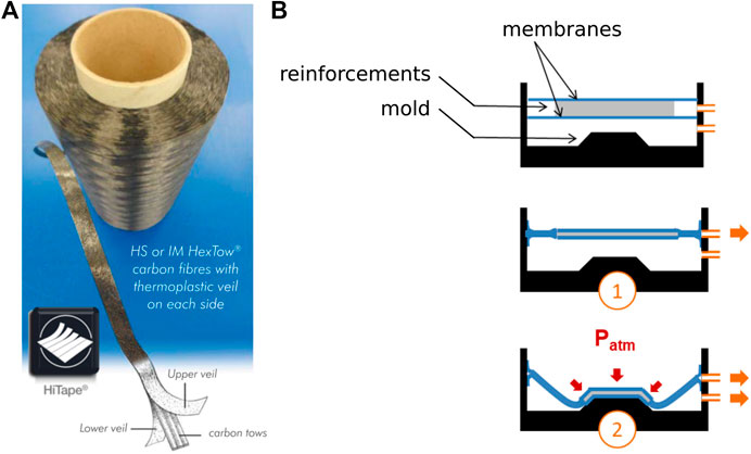
FIGURE 1. Industrial context: (A) HiTape® reinforcements for LCM processes (Hexcel, 2015b) and (B) schematics of double-membrane hot vacuum forming process, which consists in a compaction stage followed by a forming stage.
Going a step further in increasing production rates, dry semi-products such as HiTape® can be first deposited with automated placement in 2D stacks of several plies, and then formed in an automated way under mechanical loading to reach a given geometry and fiber arrangement. In this paper, the considered forming process solution is double-membrane hot vacuum forming as illustrated in Figure 1B. It consists firstly in compacting the dry stack between soft membranes by pulling vacuum (①), and secondly in forcing this membranes/stack set to deform (Pickett, 2018) by pulling vacuum between the mold and the membranes/stack set yielding an about 1 bar forming pressure (②). This forming step is performed above the melting temperature of the veil, notably for the veil to maintain the shape of the resulting preform. Preventing defects and imperfections (e.g., wrinkles) occurrence during this crucial forming stage is of prime importance and requires to understand the ply response to thermo-mechanical loading, and how plies move with respect to each other.
The aim of this paper is to characterize the behavior of HiTape® reinforcements in order to feed models of the forming process of stacks. To the knowledge of the authors, literature on the characterization of such dry UD materials is quite sparse. In Section 2, we hence propose a literature review on the behavior of related materials such as dry multi-axial reinforcements and pre-impregnated UDs, in order to define the major deformation modes to be identified for forming modeling, along with the corresponding appropriate experimental methods. Such review allows us to identify the most relevant deformation modes of HiTape® to be characterized: bending and inter-ply sliding. In Section 3, the implementation of corresponding dedicated experimental methods is described. Finally, results of HiTape® characterization in bending and inter-ply sliding are presented and discussed in Section 4.
From State of the Art to Considerations on Hitape® Reinforcements Mechanical Behavior
Extensive work has been performed on the characterization of the forming behavior of composite semi-products with heavy multi-axial complex architectures, either for pre-impregnated (e.g., Ten Thije et al. (2011), Lightfoot et al. (2013)) or dry reinforcements (e.g., Boisse (2004), Cao et al. (2008), Senner et al. (2014)). However, the particular structure of HiTape® is expected to yield a specific intermediate type of behavior. On one hand, an individual ply (intra-ply) is likely to respond like pre-impregnated UD materials (Leutz, 2015), i.e., with a theoretically transversely isotropic behavior, but with even less cohesion and very low stiffness in the isotropy plane orthogonal to the fiber direction. On the other hand when considering several plies forming in industrial conditions (hence at the veil melting temperature), the presence of the melted veil at the interface between plies (inter-ply) may modify HiTape® stacks response compared to multi-axial dry semi-products (Creech and Pickett, 2006). The aim of this section is to perform a selective literature review in order to identify which characterization work should be carried out on HiTape® in order to describe its mechanical behavior to be used as input for forming simulations.
Intermediate Scale of Observation
Reinforcements are intrinsically multi-scale materials as they are classically composed of thousands of fibers gathered in tows (possibly spread) which are assembled in tapes or plies, then laid up as a stack (Figure 2). The scale of observation for this study must allow for the identification of the main mechanisms which control both intra-ply and inter-ply responses during forming, but should also enable modeling the process with tractable computational efforts.
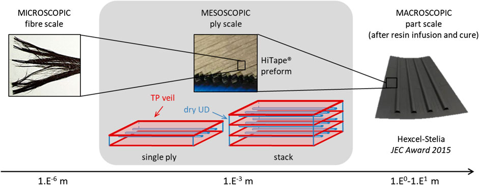
FIGURE 2. The three main scales of observation of composites materials; an intermediate (mesoscopic) ply scale is selected for forming modeling and HiTape® characterization.
Modeling the forming at fiber scale would help understanding interactions between fibers, but it is not suited for representing the forming of stacks which contain millions of fibers with specific architectures, nor accounting for the contact between top and bottom plies with the surrounding tooling. On the opposite, the part (or stack) scale is too coarse as heterogeneous layer-wize constitutive responses are expected. The material response model should indeed be able to capture local effects (inter-ply shear, frame rotations … ) which control the relative motion between plies as well as the intra-ply response itself. It should also represent the large deformations undergone by the whole stack, which translate into finite strains and rotations that a continuous approach can certainly not handle even with refined kinematics (Dufort et al., 2001). Eventually, an intermediate scale, so-called mesoscopic, is considered for modeling HiTape® forming as well as to characterize the ply and stack responses. Indeed, as illustrated in Figure 2, modeling each ply through an equivalent homogeneous medium (potentially non-linear and orthotropic) ensures acceptable computational efforts (Fagiano, 2010; Dörr et al., 2017) while allowing for a reasonably fine description of the mechanisms acting in the ply and between plies (Bouquerel et al., 2017).
Deformation Modes at ply Scale During Forming and Corresponding Characterization Methods
As illustrated in Figures 3A,B, reinforcements exhibit both in-plane and out-of-plane (i.e. along thickness direction) intra-ply deformation mechanisms: traction, compression as well as shear. Moreover, like any fibrous medium, HiTape® may also display structural modes like out-of-plane bending due to the reinforcement intrinsic thickness. Finally, these intra-ply modes must be complemented by specific ones associated with the presence of the TP veil on either side of the layers, which come into play when considering HiTape® stacks. These inter-ply modes correspond to sliding or opening/closing as presented in Figure 3C.

FIGURE 3. Deformation mechanisms of reinforcements at ply scale during forming, illustrated in the case of a UD with fibers oriented along
In this section let us consider these intra- and inter-ply deformation modes and how the corresponding responses can be identified. We shall not describe all these modes in detail, but focus on the predominant ones during forming.
Tensions and Compressions
The longitudinal response along fiber direction
In transverse directions
In transverse compression, the response of the fibrous material is driven by the fiber network rearrangement as well as fiber-to-fiber contacts (Xiong et al., 2019). Recalling that we consider double-membrane forming processes where the individual layers of the stack are compacted along thickness direction (
Shears
Considering the small thickness of HiTape® (approximately 0.2 mm), we can assume that transverse shear–i.e. in planes
To the knowledge of the authors, literature on the characterization of the in-plane shear behavior of dry UD reinforcements under forming conditions is quite sparse. Related studies may be found for UD-NCF (Trejo et al., 2020) as well as for pre-impregnated UD tapes with various strategies proposed to maintain the specimen integrity during testing: Leutz (2015) tested 4-ply stacks (Figure 4), McGuinness and Bradaigh (1998) used membranes to maintain a single ply but struggled to isolate the ply response from the membrane one, and Larberg et al. (2012) considered cross-plied. However, all these tests demonstrated a rapid decohesion following the occurrence of out-of-plane instabilities, either fiber micro-buckling or ply buckling. Due to the only superficial cohesion of HiTape®, in-plane shear characterization seems out of reach from a technological point of view. More importantly, due to the compaction which limits the fiber transverse displacements during forming, the formability of a stack of HiTape® plies is expected to be driven more by the relative motion of thin HiTape® individual plies than by intra-ply in-plane shear as it is highlighted in the following.
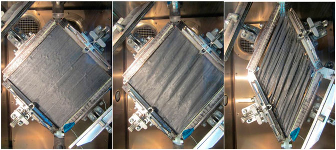
FIGURE 4. An example of in-plane shear characterization of pre-impregnated UD carbon/epoxy: picture-frame test on a 4-ply stack of UD of same orientation (left to right: initial configuration, intermediate shear angle of 2°, final shear angle of 40°) (Leutz, 2015).
Out-of-Plane Bending
Many recent studies showed that accounting for ply scale out-of-plane bending behavior of either dry or pre-impregnated semi-products (Cao et al., 2008; Haanappel et al., 2014) in forming simulations allows the prediction of wrinkles occurrence in thick architectures (Boisse et al., 2011), and more generally is a step forward to reliable simulations (Madeo et al., 2015). Moreover, even for thin plies, the bending behavior controls the overall formability to a great extent (Liang et al., 2014). Although the hypothesis of continuity is often made for fibrous media–especially those with high fiber volume fraction–, bending behavior cannot be directly deduced from the elongation stiffness for these media, mainly because of internal relative motion between fibers during deformation (Kang and Yu, 1995). For this reason, reinforcements bending behavior should be characterized.
Due to the low bending stiffness of composite semi-products, classical characterization methods such as three- or four-point bending tests have classically been discarded by the textile industry. Peirce (Peirce, 1930) early proposed a ply scale linear elastic bending model for cloth, extending Euler-Bernoulli’s beam theory to large deflections but small deformations using a correction term. This model led to a simple, cost-effective and rapid bending characterization method called fixed angle flexometer, and involving a strip of fabric bending under its own weight. Using this method Leutz (2015) measured the bending stiffnesses
Going a step forward, fibrous semi-products were shown to exhibit a non-linear bending response (Liang et al., 2014). Their tangent behavior can be more generally defined by the differential form
In order to characterize this particular behavior, a specific apparatus called Kawabata Evaluation System KES-FB2 (Kawabata, 1980) was designed and successfully used on fabrics (Ngo Ngoc et al., 2002) and non-crimp fabric (NCF) multi-plies (Lomov et al., 2003) for example; however this type of apparatus is rather cumbersome and limited to room temperature. Other characterization methods were further derived from the fixed angle flexometer test to characterize non-linear behaviors: de Bilbao et al. (2008) increased step by step the free length of the strip for NCFs and interlocks, while other approaches were based on recording the deformed shape of the sample and using image processing to relate the bending moment to the sample curvature. In order to characterize a wide range of curvatures, Liang et al. (2014) also added a lumped mass at the end of the strip.
Besides, some methods were developed to take into account the temperature-dependency of the bending behavior of pre-impregnated reinforcements, for UD carbon/PEEK1 and UD carbon/PPS2 for example (Liang, 2016). In those studies, managing the increase of temperature in the sample before testing was reported to be challenging. A specific apparatus called hot vertical cantilever (Soteropoulos et al., 2011; Alshahrani and Hojjati, 2017) was hence proposed in order to load the sample only when the desired temperature was reached. However, a deformation of the sample was already observed before applying the load due to the temperature rise (Angel and Graef, 2016). In addition, the homogeneity and control of the environment are critical and can significantly influence the results (Angel and Graef, 2016). To overcome this, other tests were proposed on smaller volumes: for instance in a 3-point bending DMA machine (Margossian et al., 2015) or with a rheometer (Sachs et al., 2014).
Inter-ply Response
The two inter-ply deformation modes are depicted on Figure 3C, namely inter-ply opening (decohesion) and sliding. In the case of double-membrane forming processes, it seems wise to assume that decohesion along direction
Characterization Methods of Inter-Ply Sliding
Standard methods were developed for the characterization of the frictional behavior of sheets of materials–standards related to inter-fiber or inter-tow friction are not discussed here. They involve a fixed plane, either horizontal or inclined, onto which a first sample of tested material is attached, and over which a mobile block holding a second sample is translated. The static (i.e. when relative motion is initiated) and dynamic (i.e. during relative motion) friction coefficients are calculated using Coulomb’s law, which assumes that friction coefficients are independent of both relative sliding velocity and normal pressure:
where CoF is the friction coefficient, and
However, these methods have been developed to represent friction conditions that sheet materials may encounter during handling or automated processing, but they are not representative of composite forming conditions. Indeed, not only are they limited to room temperature, but the required force corresponding to forming (i.e. of the order of magnitude of a few hN for standard tests) cannot be applied with such methods. Those are the reasons why other tests were developed for composite semi-products friction characterization. A horizontal plane with a specific system for applying normal pressure was proposed by Hivet et al. (2012), Montero et al. (2017), but the pressure still seems too low for our forming conditions. To achieve normal pressures of about 1 bar, the pull-out and the pull-through tests (illustrated on Figure 5A) are the most common ones; they are described in the benchmark of Sachs et al. (2012). In these tests, a reinforcement sample (referred to as central specimen) is placed between two plates covered with reinforcement samples (referred to as lateral specimens) and a normal force is applied. The central sample is then loaded in tension and forced to slide, while the corresponding force is recorded. The difference between the two apparatuses lies in the contact area, which is constant during the test for the pull-through while it decreases for the pull-out.
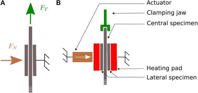
FIGURE 5. (A) Principle of the pull-through test and (B) schematic of the inter-ply friction characterization setup.
Inter-ply Friction Behavior of Reinforcements
In the literature, Coulomb’s law (Eq. 1) for dry friction is generally used to model the friction behavior during inter-ply sliding of solid-state reinforcements, i.e. either dry (Hivet et al., 2012) or containing thermoplastic below its melting temperature (Sachs et al., 2012) as illustrated in Figure 6B (top). Indeed, after a transient phase, the coefficient of friction reaches a plateau value often interpreted as the dynamic coefficient of friction. However, the hypothesis of a single constant friction coefficient for solid-state reinforcements is too coarse; normal pressure in particular has a strong influence on the friction coefficient Hivet et al. (2012). Thus more complex models were proposed; for example Howell’s model (Howell and Mazur, 1953) describes a power law between tangent and normal forces such that
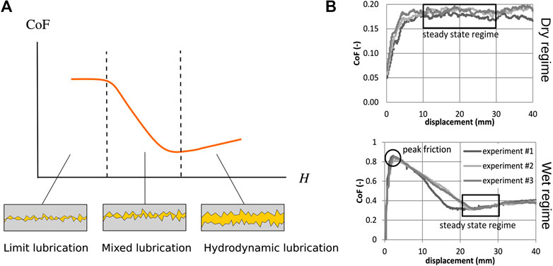
FIGURE 6. (A) Stribeck curve and schematic illustration of the different lubrication regimes and (B) examples of dry (top) and wet (bottom) friction for Twintex® PP from Sachs et al. (2012).
As soon as the reinforcement contains resin in a molten state, this resin may play the role of a lubricant and strongly influences the friction response; this is called lubricated contact. In that case, the friction coefficient depends on resin viscosity η, sliding speed ν and normal force applied
Based on a phenomenological approach, Stribeck’s theory (Stribeck, 1903) expresses the existence of a minimum on the curve of friction coefficient vs. Hersey number. Three different lubrication regimes illustrated on Figure 6A can then be highlighted. In the limit regime, the lubricating film is very thin, i.e. its thickness is of the same order of magnitude as the roughness of the two surfaces; in this case the friction behavior depends both on the lubricant and the physico-chemical properties of the surfaces. In the mixed regime, there co-exist some areas where the two surfaces are in direct contact and some areas where they are separated by a lubricating film (Frêne and Zaïdi, 2011). In the hydrodynamic regime, the two surfaces are completely separated by a lubricating film; the roughness of the surfaces is then negligible. In this case, the relationship between the friction coefficient and the Hersey number is increasing linearly (Hersey, 1914). Stribeck’s theory was frequently used for either thermoplastic (Gorczyca et al., 2007; Ten Thije et al., 2011; Vanclooster et al., 2010; Fetfatsidis et al., 2013; Zhu et al., 2011; Wang et al., 2013) or thermoset (Rashidi et al., 2020) pre-impregnated reinforcements friction characterization for forming modeling. In this case of reinforcements containing a resin in the fluid state, the same type of curve with stabilization of the friction coefficient is obtained as illustrated in Figure 6B (bottom), and a hydrodynamic regime is generally observed. Affine (Najjar et al., 2014) or power laws (Haanappel et al., 2014) for example can be used to relate the friction coefficient to the Hersey number; in other cases, the hydrodynamic regime is directly assumed (Bel et al., 2012). If the normal pressure is high, the resin at the interface may migrate and limit lubrication may occur: a mixed lubrication model is then more suitable (Larberg and Akermo, 2011; Leutz, 2015). For reinforcements containing molten thermoplastic, the friction coefficient varies over a wider range, for example values between 0.1 and 1.8 were measured by Sachs et al. (2012).
In both cases (presence or not of a resin in a fluid state), during the transient regime prior to stabilization of the tangential force, the latter can reach a maximum value (Figure 6B) which becomes more evident as the velocity increases (Ten Thije et al., 2011). If Fetfatsidis et al. (2013) used this maximum force value to deduce a static coefficient of friction, this interpretation is however not unanimous. Indeed, in the case of the work of Ten Thije et al. (2011), the tangent force peak did not correspond to the initiation of relative motion but to a displacement value already higher than the one matching the maximum elongation of the sample before rupture. This means that the sample had already started to slide, and this maximum coefficient of friction did not correspond to a static coefficient of friction. Instead, the transition from peak to plateau was interpreted as a rearrangement of the reinforcement.
Finally, a dependence of the friction coefficient upon fiber orientation was observed. Testing a carbon/epoxy UD, Leutz (2015) for example obtained a friction coefficient varying from 0.88 for orientations of 0°/90°3 to 1.37 for 0°/0°, with an intermediate value for 90°/90°. Larberg and Akermo (2011), who identified a mixed lubrication model, obtained on the same type of material a maximum coefficient of friction for 0°/45° and 0°/30°, about 25% higher than that obtained with orientations of 0°/90°and 0°/0°.
Conclusions on HiTape® Characterization Strategy
The literature review conducted so far highlights the two deformation mechanisms that primary require characterization in order to feed forming simulations of HiTape®: bending and inter-ply friction. In particular for inter-ply friction, the presence of the TP veil (which differs from a continuous film) raises the question of which of the mixed or hydrodynamic lubrication regime predominates. Such characterization works need to be conducted under conditions as close as possible from double-membrane vacuum hot forming process, hence at the forming process temperature (which is above the melting temperature of the TP veil) and for external pressures between 0.5 and 1.5 bar. In the following, the selected methods for both non-linear bending behavior and interply friction behavior characterizations are introduced.
Materials and Methods
Materials
The characterized HiTape®4 reinforcement was composed of Hexcel HexTow® fibers with a thermoplastic veil on each side of the tape. This tape was 12.7 mm wide and had an areal weight of 210 g/m2.
Out-of-Plane Bending Characterization Method
In order to characterize the non-linear bending behavior of HiTape® at ply scale and at the forming process temperature (
Test Setup
The bending test apparatus, represented in Figure 7B, was composed of a frame with a specimen holder developed to limit edge effect due to the clamp. Thermocouples were used for temperature monitoring. This apparatus was placed in a thermoregulated oven equipped with a glass window. A CCD camera was positioned outside the oven and a LabVIEW program5 recorded in real time both photographs of the sample and temperature of the thermocouples, with a chosen acquisition frequency and duration. A set of masses to be positioned at the free end of the sample was available to increase sample curvature. The grip system to attach the selected mass to the sample tip justified to model it as a point force oriented with gravity.

FIGURE 7. (A) Principle and notations for the bending moment calculation with Eq. 7 and (B) schematic of the bending test.
Test Procedure
The sample (either unit plies or stacks obtained with DFP) was first pre-consolidated under vacuum at
Data Post-processing
Using the output photograph of the deformed sample, the cartesian coordinates
1. Derive the relationship
which is referred to as deformed shape function thereafter. This particular form illustrated for instance in Figure 8A is justified in Section 4.1.2.1.
2. Compute curvature
3. Compute curvilinear abscissa
4. Compute bending moment per unit width
where s is the curvilinear abscissa at point A such that
5. Derive a relationship between bending moment and curvature
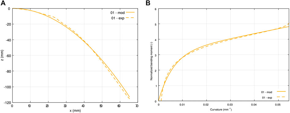
FIGURE 8. Comparison between experimental data (dashed lines) and model (solid lines) for a single ply tested at room temperature: (A) deformed sample mean line with
Voce’s model (Pannier, 2006) is illustrated in Figure 8B and its justification is given in Section 4.1.2.1.
The outputs of the corresponding program were the following: the range of curvatures of the deformed sample, the optimized couple (
The two successive regressions–firstly on coordinates
For commodity reasons, these errors were normalized by the range of values obtained experimentally. We could then define the two following validity criteria for any tested sample:
Inter-ply Friction Characterization
Based on previous studies (Gorczyca et al., 2007; Vanclooster et al., 2010; Ten Thije et al., 2011; Zhu et al., 2011; Fetfatsidis et al., 2013; Wang et al., 2013), the pull-through test principle was selected to characterize HiTape® inter-ply lubricated friction at ply scale. Let us recall the principle of this test illustrated on Figure 5A: a central sample is placed in-between two fixed lateral samples and a controled normal pressure is applied across the thickness of the reinforcements, the central sample is then pulled through the setup. The tensile traction force
The test setup was designed such that conditions representative of double-membrane vacuum hot forming were covered. As forming pressure is about 1 bar–but may vary locally –, normal stresses in the range 0.5–1.5 bar were considered. The relative speed between two adjacent plies was tricky to estimate; in the case of vacuum forming, which is a slow forming process, a relative speed of the order of magnitude of a few millimeters in some seconds was considered, i.e., 1–10 mm min−1. Finally, the forming process temperature
Test Setup
A fixture was designed both to hold the lateral specimens in place and to apply the desired normal pressure and temperature conditions. Figure 5B provides a schematic of the final bench. The closing pressure was prescribed by an actuator. The lateral samples were placed in contact with heating pads and were fixed by means of a specific system. This apparatus was designed to be mounted on a standard traction machine, and the central sample attachement was fixed to the crosshead of the machine. The test was controled using the traction machine software, and an acquisition station enabled the force, displacement, and time data of the traction machine to be recorded in real time, as well as the temperature of the heating pads.
Temperature homogeneity inside the samples was checked by placing thermocouples in the central sample just upstream of the test area and carrying out the test: it was then verified that when the thermocouple came into the test area, i.e. in contact with the heating pads, the setpoint temperature
Test Procedure
The test procedure consisted first in fixing both lateral specimens to the heating pads and clamping the central specimen in the upper attachement of the traction machine crosshead. The actuator was then activated to apply the closing pressure, and the temperature of the pads increased up to the setpoint temperature
Data Post-processing
The friction coefficient CoF and modified Hersey number
where
Results and Discussion
Out-of-Plane Bending
The out-of-plane bending characterization was achieved in three steps: first some tests on single plies were performed in order to validate the proposed methodology, then single plies were characterized, and finally the method was extended to UD stacks to get closer to industrial needs. For confidentiality reasons, all the moment values presented are normalized.
Results
Preliminary Tests on Single Plies at Room Temperature
Preliminary tests were first conducted in order to validate the proposed methodology; these tests were carried out at room temperature to validate the approach in lighter conditions. In order to assess the test repeatability, 10 samples were first tested at room temperature with the same lumped mass
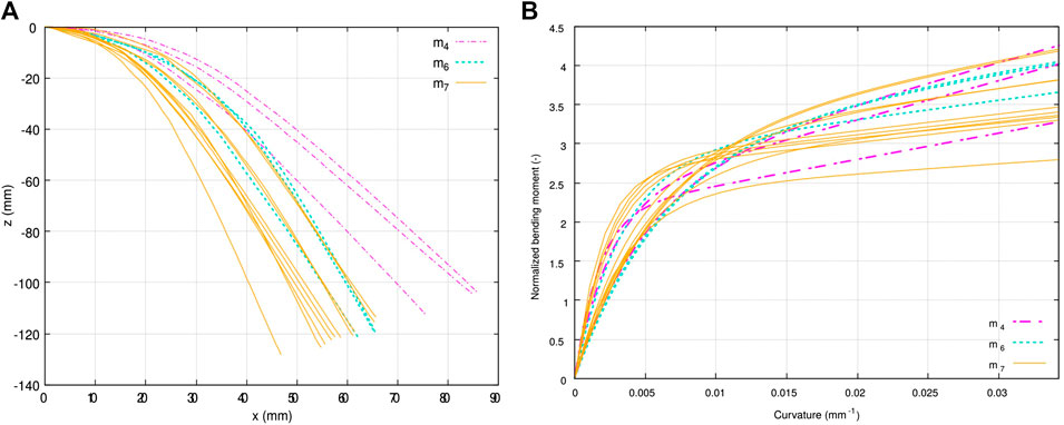
FIGURE 9. Results of bending tests on single plies at room temperature using three different lumped masses
This test was repeated with two other lumped masses
Results for Single Plies at
In order to identify the out-of-plane bending behavior of single plies under forming conditions, tests were conducted at
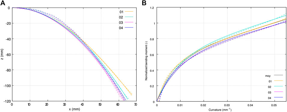
FIGURE 10. Results of bending tests on single plies at
In Figure 10B, curvatures and normalized bending moments computed using Eqs 4 and 7, respectively, are plotted for the four samples, as well as the corresponding optimized Voce’s models (Eq. 8). The average model is also plotted, its parameters
Results on Stacks at
The bending test was extended to UD stacks of two, four, six and eight plies, with at least three samples for each. Tests on six- and 8-ply stacks could not be processed since the validity criteria were not satisfied. Figure 11A presents the averaged bending moment vs. curvature for various numbers of plies including a single ply, obtained by averaging Voce’s model triplets of parameters. One can notice, again, that the Voce’s model enabled to describe properly the moment-curvature evolution for either single plies, two- or 4-ply stacks.
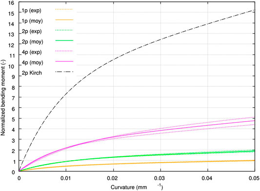
FIGURE 11. Normalized bending response at
Discussion
Comments on the Choice of the Models
Let us first observe in Figure 8 the deformed shape and the moment-curvature relationship obtained for one sample tested at room temperature, meeting the validity criterion. The results presented in this figure exhibit a very low error between the deformed function and the mean-line obtained using image processing. This was also demonstrated with further results plotted in Figure 10A where
Besides, Figure 8B shows that the selected Voce’s model (Eq. 8) satisfactorily described the moment-curvature relationship obtained experimentally, with little error. Again, this tendency was more general as illustrated in Figure 10B with a very low error on the moment (
Overall, the proposed models yielded a good fit of the experimental data. In Figures 8B,10B, it can be observed that the major differences between the raw results and the Voce’s model (Voce, 1955) are located either at the foot of the curve (low moments and low curvatures) corresponding to the free end of the sample where the moment vanishes, or at the end of the curve (high moment and high curvatures) corresponding to the clamp where the moment is maximum. Firstly, with regard to the foot of the curve, it should be noted that while the computed bending moment exactly equals zero at the free end of the sample, the curvature tends toward zero but only approximately because of the deformed shape function used (Eq. 3). This is not physical as it would describe a deformation in a stress-free state. Therefore we chose to impose
Using intermediate models to build the moment-curvature relationship required to estimate the error introduced by the two successive regressions. The uncertainty on bending stiffness B due to the uncertainty on curvature κ is given by:
This shows that the initial tangent stiffness (i.e. for
Comments on the Curvature Range Covered
In these tests, the curvatures described by the deformed functions were between 0.0576 and 0.0010 mm−1, which correspond to curvature radii from 17 to 1,000 mm approximately. Our aim was to describe curvatures representative of industrial geometries, for which curvature radii can reach 5 mm (corresponding to a curvature of 0.2 mm−1). Such high curvature could not be reached experimentally with this method without the occurrence ofùtextitbreaks in the deformed shape, as explained earlier. However, since Voce’s model is linear beyond the threshold curvature which is much lower than 0.2 mm−1 (
Comments on the Identified Responses
First, a comparison between Figures 9B,10B highlights that with increasing temperature the bending moment is reduced for a given range of curvature. The softening effect of temperature is observed with a stiffnesses ratio between the two temperatures of the order of
The results obtained at
One limitation of this bending test was the thickness of the specimens, as it limited the number of plies of the tested stacks. Indeed, a too large thickness (or number of plies) led to the local buckling phenomenon explained earlier: an opening (fish-eye) induced by the through-thickness decohesion of the sample appeared. This phenomenon was due both to the inextensibility of individual fibers and to local singularities. In that case, the hypothesis of continuity of the material, and consequently the interpretation of the results according to the above method, were no longer valid. It was therefore decided to minimize these effects, which consisted in reducing the sample curvature by decreasing the additional mass. However, lower curvatures were obtained and therefore the quasi-linear response could not be appropriately described as the value of the regression parameter
With this method we characterized the bending responses of single plies as well as two- and 4-ply stacks at
Theses differences can certainly be partly attributed to the invalidity of the continuous medium theory in this context, as there may have been some fibrous rearrangements during testing, but we also assume that they are accentuated by the presence of the thermoplastic veil at the inter-ply. Indeed, during the bending of a stack, the fiber inextensibility induces transverse shear which can only concentrate in the soft TP veil, otherwise out-of-plane buckling of plies in the inner curvature would occur (Drapier et al., 1996, 2001). In other words, this means that the overall forming capability of the stack originates from inter-ply sliding. In conclusion, either for single plies or stacks, the continuous media (Cauchy) theory can clearly not describe the response of single HiTape® plies, and the major role of the TP veil is demonstrated in the bending of a stack.
Inter-Ply Sliding
Results
Let us recall the pressure and speed ranges representative of hot vacuum forming conditions that we introduced in Section 3.3: pressures around 1 bar and relative speeds of two adjacent plies of the order of magnitude of a few millimeters in some seconds, i.e. 1–10 mm min−1. In order to assess the relative influence of velocity and normal pressure in thoses ranges, five configurations were tested with four to five samples each. Keeping speed at 2.0 mm min−1, tests were carried out at 1.35, 1.00 and 0.50 bar, respectively. Tests at bounding pressures of 1.35 and 0.50 bar were also performed at 0.5 mm min−1. As this work was the first inter-ply sliding characterization of HiTape®, we decided to focus on 0°/0° sliding, i.e. both lateral and central specimen were aligned with loading direction.
The resulting tangent force vs. displacement curves (not presented for confidentiality reasons) exhibited the same shape than wet friction results of friction coefficient vs. displacement from literature, for example from Sachs et al. (2012) (Figure 6B bottom). Such comparison makes sense as friction coefficient is related to tangent force only by normal force which is kept constant during the test. After tensionning of the sample, displacement initiated (at a tangent force value
The results of static and maximum coefficients of friction are presented with their standard deviations as a function of pressure in Figure 12 and as a function of the relative speed in Figure 13. A strong influence of pressure and velocity was observed in the ranges of pressure and velocity studied. Note that the standard deviations on every configuration were small (less than 10%) compared to the differences observed from one configuration to another.
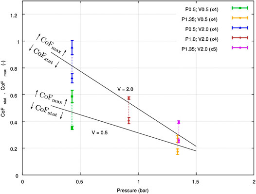
FIGURE 12. Results of inter-ply sliding test: maximum and static friction coefficients vs. pressure.
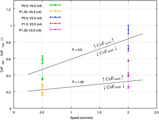
FIGURE 13. Results of inter-ply sliding test: maximum and static friction coefficients vs. adjacent plies relative speed.
Discussion
The shape of the tangent force-displacement response obtained was consistent with literature results presented for composites pre-impregnated with a TP resin tested in a molten state, as illustrated in Figure 6B taken from Sachs et al. (2012). However, unlike in Ten Thije et al. (2011) and Fetfatsidis et al. (2013), the tangent force measured in our experiment did not clearly stabilize. Consequently, we could not extract from the presented tests a dynamic fiction coefficient. This phenomenon is attributed to a fibrous rearrangement during the test and to possible penetration of the veil inside the UD fiber bed.
When forming a stack, the expected relative displacement between two adjacent plies is of the range of a few millimeters. Moreover, purely geometrical considerations show that forming two 0.2 mm thick inextensible layers on a quadrant implies a relative displacement between of 0.3 mm the two layers. This highlights that only the very first millimeters of sliding of the test are of interest for us. Using bounding values of
In order to conclude on the type of lubricated regime that characterizes the inter-ply response during hot forming, both coefficients of friction obtained
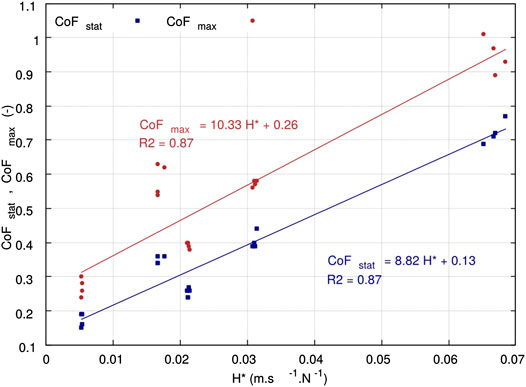
FIGURE 14. Stribeck curve for HiTape® over the pressure and speed ranges representative of double-membrane hot vacuum forming conditions.
Conclusion
In this work, the deformation mechanisms of HiTape® reinforcements were inventoried: intra-ply mechanisms control the response of a single ply, and inter-ply mechanisms (especially inter-ply sliding) are involved when considering the forming of stacks. More precisely, HiTape® mainly deforms in bending (and forms wrinkles) which is controled by the fiber response as well as the presence of the TP veil that acts between plies as a lubricating layer providing shear compliance especially at the forming process temperature (which is above the veil melting temperature). This study was therefore dedicated to the characterization of two deformation modes encountered by HiTape® reinforcements during double-membrane hot vacuum forming process and for which the behavior was unknown, namely out-of-plane bending and inter-ply friction. Dedicated apparatuses were designed on purpose, in order to meet the requirements of handling, heating, and finely controling the characterization of non-linear bending response and inter-ply sliding in conditions representative of the industrial double-membrane hot vacuum forming processes.
For bending, a modified Peirce’s flexometer was designed and validated. It enabled to assess the complete isothermal moment-curvature non-linear relationship in a single test, taking advantage of the curvature range covered by the deformation of single plies and stacks under a terminal loading that could be adjusted to reach the curvatures in scope. The bending responses identified correspond to fibrous media bending for which the internal mobility of the fibers leads to a range of stiffnesses much lower that what can be expected in continuous Cauchy’s media with the same elongational modulus. Also, the bending stiffnesses identified for stacks clearly showed that the thermoplastic veil between plies has a strong influence and controls to a high extent the stack bending overall response.
Such results justified the development of a second apparatus designed for the characterization of inter-ply friction: a pull-through test with controled temperature and pressure. A hydrodynamic lubricated friction regime was observed through a linearly increasing relationship between the friction coefficients–both static and maximum–and the modified Hersey number (divided by the assumed constant viscosity of the thermoplastic veil). From an industrial point of view, this result showed that in order to limit the occurrence of wrinkle-type defects during forming, inter-ply sliding should be promoted with forming conditions inducing high pressure and low velocity. This guideline should be verified in further work with dedicated forming experiments.
Data Availability Statement
The datasets presented in this article are not readily available because they are confidential. Requests to access the datasets should be directed to bGF1cmUuYm91cXVlcmVsQGhleGNlbC5jb20=.
Author Contributions
LB: main co-author, the material presented herein comes out from her PhD work. NM: LB’s co-supervisor and co-contributor to this article. SD: LB’s main supervisor and co-contributor to this article.
Funding
This work produced in LB’s PhD was supported both by ANRT, the French National Agency for Research and Technology, under the grant 2016/0094, and by the company Hexcel Reinforcements SASU.
Conflict of Interest
LB was employed by the company Hexcel Reinforcements SASU.
The remaining authors declare that the research was conducted in the absence of any commercial or financial relationships that could be construed as a potential conflict of interest.
Footnotes
1PEEK: PolyEtherEtherKetone
2PPS: PolyPhenylene Sulfide
3Orientation of samples in contact, in degrees with respect to loading direction.
4Permission from the product owner was obtained for this study.
5www.ni.com/fr-fr/shop/labview.html
References
Abbott, G. M., Grosberg, P., and Leaf, G. A. V. (1971). The mechanical properties of woven fabrics Part VII : the hysteresis during bending of woven fabrics. Textil. Res. J. 41, 345–358. doi:10.1177/004051757104100411
Alshahrani, H., and Hojjati, M. (2017). A new test method for the characterization of the bending behavior of textile prepregs. Composites Part A : Applied Science and Manufacturing. 97, 128–140. doi:10.1016/j.compositesa.2017.02.027
Angel, B., and Graef, J. (2016). Study of the bending stiffness of fibre-reinforced thermoplastics at forming temperature. JEC Composites Magazine., 103, 76–79.
Bel, S., Hamila, N., Boisse, P., and Dumont, F. (2012). Finite element model for NCF composite reinforcement preforming: composites Part A: applied Science and manufacturing: importance of inter-ply sliding. Compos. Part A: Appl. Sci. Manuf. 43 (12), 2269–2277. doi:10.1016/j.compositesa.2012.08.005
Blais, M. (2016). Modélisation et suivi du procédé par infusion de résine sur une nouvelle génération de renforts structuraux pour l’aéronautique. PhD. thesis, Saint-Étienne (France): Ecole Nationale Supérieure des Mines de Saint-Etienne.
Blais, M., Moulin, N., Liotier, P. J., and Drapier, S. (2017). Resin infusion-based processes simulation : coupled Stokes-Darcy flows in orthotropic preforms undergoing finite strain. Int. J. Material Form. 10 (1), 43–54. doi:10.1007/s12289-015-1259-2
Boisse, P., Hamila, N., Vidal-Sallé, E., and Dumont, F. (2011). Simulation of wrinkling during textile composite reinforcement forming. Influence of tensile, in-plane shear and bending stiffnesses. Compos. Sci. Technol. 71, 683–692. doi:10.1016/j.compscitech.2011.01.011
Boisse, P. (2004). Mise en forme des renforts fibreux de composites. Techniques de l’ingénieur Plasturgie: procédés spécifiques aux composites Ref: TIB474DUO. Article ref: am3734
Bouquerel, L., Moulin, N., Drapier, S., Boisse, P., and Beraud, J.-M. (2017). Modelling and simulating the forming of new dry automated lay-up reinforcements for primary structures. AIP conference proceedings. 1896 (1), 030008. doi:10.1063/1.5007995
Cao, J., Akkerman, R., Boisse, P., Chen, J., Cheng, H. S., de Graaf, E. F., et al. (2008). Characterization of mechanical behavior of woven fabrics: experimental methods and benchmark results. Compos. Appl. Sci. Manuf. 39, 1037–1053. doi:10.1016/j.compositesa.2008.02.016
Celle, P., Drapier, S., and Bergheau, J. M. (2008). Numerical aspects of fluid infusion inside a compressible porous medium undergoing large strains. European Journal of Computational Mechanics. 18, 819–827. doi:10.3166/remn.17.819-827
Charmetant, A. (2011). Approches hyperélastiques pour la modélisation du comportement mécanique de préformes tissées de composites. PhD. thesis, Villeurbanne (France): Institut National des Sciences Appliquées de Lyon
Clapp, T. G., Peng, H., Ghosh, T. K., and Eischen, J. W. (1990). Indirect measurement of the moment-curvature relationship for fabrics. Textil. Res. J. 60, 525–533. doi:10.1177/004051759006000906
Cornelissen, B., Sachs, U., Rietman, B., and Akkerman, R. (2014). Dry friction characterisation of carbon fibre tow and satin weave fabric for composite applications. Composites Part A : Applied Science and Manufacturing. 56, 127–135. doi:10.1016/j.compositesa.2013.10.006
Creech, G., and Pickett, A. K. (2006). Meso-modelling of non-crimp fabric composites for coupled drape and failure analysis. J. Mater. Sci. 41 (20), 6725–6736. doi:10.1007/s10853-006-0213-6
Das, A., Kothari, V. K., and Vandana, N. (2005). A study on frictional characteristics of woven fabrics. Autex Res. J. 5 (3)., 133–140
de Bilbao, E., Soulat, D., Hivet, G., and Gasser, A. (2010). Experimental study of bending behaviour of reinforcements. Exp. Mech. 50, 333–351. doi:10.1007/s11340-009-9234-9
de Bilbao, E., Soulat, D., Hivet, G., Launay, J., and Gasser, A. (2008). Bending test of composite reinforcements. Int. J. Material Form. 1, 835–838. doi:10.1007/s12289-008-0265-z
Dörr, D., Brymerski, W., Ropers, S., Leutz, D. M., Joppich, T., Kärger, L., et al. (2017). A benchmark study of finite element codes for forming simulation of thermoplastic UD-Tapes Procedia CIRP. 66. 101–106. doi:10.1016/j.procir.2017.03.223
Drapier, S., Grandidier, J.-C., Gardin, C., and Potier-Ferry, M. (1996). Structure effect and microbuckling. Composites Scicence and Technology. 56 (7), 861–867. doi:10.1016/0266-3538(96)00033-4
Drapier, S., Grandidier, J. C., and Potier-Ferry, M. (2001). A structural approach of plastic microbuckling in long fibre composites: comparison with theoretical and experimental results. Int. J. Solid Struct. 38, 3877–3904. doi:10.1016/S0020-7683(00)00247-X
Drapier, S., and Wisnom, M. R. (1999). Finite-element investigation of the compressive strength of non-crimp-fabric-based composites. Compos. Sci. Technol. 59, 1287–1297. doi:10.1016/S0266-3538(98)00165-1
Dufort, L., Drapier, S., and Grédiac, M. (2001). The cross section warping in short beams under three point bending : an analytical study. Compos. Struct. 52, 1233–1246.
Fagiano, C. (2010). Computational modeling of tow-placed composite laminates with fabrication features. PhD thesis. Delft (Netherlands): Technische Universiteit Delf.
Fetfatsidis, K. A., Jauffrès, D., Sherwood, J. A., and Chen, J. (2013). Characterization of the tool/fabric and fabric/fabric friction for woven-fabric composites during the thermostamping process. Int. J. Material Form. 6, 209–221. doi:10.1007/s12289-011-1072-5
Frêne, J., and Zaïdi, H. (2011). Introduction à la tribologie. Techniques de l’ingénieur : frottement et usure Ref: TIB464DUO. Article ref:TRI 100-1
Gorczyca, J. L., Sherwood, J. A., and Chen, J. (2007). A friction model for thermostamping commingled glass-polypropylene woven fabrics. Composites Part A : Applied Science and Manufacturing. 38 (2), 393–406. doi:10.1016/j.compositesa.2006.03.006
Grosberg, P. (1966). The mechanical properties of woven fabrics Part II: the bending of woven fabric. Textil. Res. J. 36, 205–211. doi:10.1177/004051756603600301
Guzman-Maldonado, E., Wang, P., Hamila, N., and Boisse, P. (2019). Experimental and numerical analysis of wrinkling during forming of multi-layered textile composites. Compos. Struct. 208, 213–223. doi:10.1016/j.compstruct.2018.10.018
Haanappel, S. P., ten Thije, R. H. W., Sachs, U., Rietman, B., and Akkerman, R. (2014). Formability analyses of uni-directional and textile reinforced thermoplastics. Composites Part A : Applied Science and Manufacturing. 56, 80–92. doi:10.1016/j.compositesa.2013.09.009
Hersey, M. D. (1914). The laws of lubrication of horizontal journal bearings. J. Wash. Acad. Sci. 4, 542–552. doi:10.2307/24520857
Hexcel, (2015a). Direct processes technology manual. Tech. rep. Available at: https://www.hexcel.com/Resources/Technology-Manuals.
Hexcel, (2015b). HiTape® A new efficient composite technology for primary aircraft structures. SAMPE J. 51, 7–15.
Hivet, G., Allaoui, S., Cam, B. T., Ouagne, P., and Soulat, D. (2012). Design and potentiality of an apparatus for measuring yarn/yarn and fabric/fabric friction. Exp. Mech. 52, 1123–1136. doi:10.1007/s11340-011-9566-0
Howell, H. G., and Mazur, J. (1953). Amontons’ law and fibre friction. Journal of the Textile Institute Transactions. 44, T59–T69. doi:10.1080/19447025308659728
Huang, N. C. (1979). Finite biaxial extension of completely set plain woven fabrics. J. Appl. Mech. 46, 651. doi:10.1115/1.3424621
Kang, T. J., and Yu, W. R. (1995). Drape simulation of woven fabric by using the Finite-element method. J. Textil. Inst. 86, 635–648. doi:10.1080/00405009508659040
Kawabata, S. (1980). The standardization and analysis of hand evaluation. 2nd edn. (Osaka, Japan: Hand Evaluation Standardization Committee).
Larberg, Y. R., Akermo, M., and Norrby, M. (2012). On the in-plane deformability of cross-plied unidirectional prepreg. J. Compos. Mater. 46, 929–939. doi:10.1177/0021998311412988
Larberg, Y. R., and Akermo, M. (2011). On the interply friction of different generations of carbon/epoxy prepreg systems. Composites Part A : Applied Science and Manufacturing. 42, 1067–1074. doi:10.1016/j.compositesa.2011.04.010
Leutz, D. M. (2015). Forming simulation of AFP material layups : material characterization, simulation and validation. Munich, Germany: Technische Universität München.
Liang, B. (2016). Experimental and numerical study of the bending behaviour of textile reinforcements and thermoplastic prepregs. PhD thesis, Villeurbanne, France: Institut National des Sciences Appliquées de Lyon.
Liang, B., Hamila, N., Peillon, M., and Boisse, P. (2014). Analysis of thermoplastic prepreg bending stiffness during manufacturing and of its influence on wrinkling simulations. Compos. Part A Appl. Sci. Manuf. 67, 111–122. doi:10.1016/j.compositesa.2014.08.020
Lightfoot, J. S., Wisnom, M. R., and Potter, K. (2013). A new mechanism for the formation of ply wrinkles due to shear between plies. Compos. Part A Appl. Sci. Manuf. 49, 139–147. doi:10.1016/j.compositesa.2013.03.002
Lomov, S. V., Verpoest, I., Barburski, M., and Laperre, J. (2003). Carbon composites based on multiaxial multiply stitched preforms. Part 2. KES-F characterisation of the deformability of the preforms at low loads. Compos. Part A Appl. Sci. Manuf. 34, 359–370. doi:10.1016/S1359-835X(03)00025-3
Madeo, A., Ferretti, M., Dell’Isola, F., and Boisse, P. (2015). Thick fibrous composite reinforcements behave as special second-gradient materials: three-point bending of 3D interlocks. Z. Angew. Math. Phys. 66, 2041–2060. doi:10.1007/s00033-015-0496-z
Margossian, A., Bel, S., and Hinterhoelzl, R. (2015). Bending characterisation of a molten unidirectional carbon fibre reinforced thermoplastic composite using a Dynamic Mechanical Analysis system. Compos. Part A Appl. Sci. Manuf. 77, 154–163. doi:10.1016/j.compositesa.2015.06.015
Margossian, A., Bel, S., and Hinterhoelzl, R. (2016). On the characterisation of transverse tensile properties of molten unidirectional thermoplastic composite tapes for thermoforming simulations. Compos. Part A Appl. Sci. Manuf. 88, 48–58. doi:10.1016/j.compositesa.2016.05.019
Marquardt, D. W. (1963). An algorithm for least-squares estimation of nonlinear parameters. J. Soc. Ind. Appl. Math. 11, 431–441. doi:10.1137/0111030
McGuinness, G. B., and Bradaigh, C. O. (1998). Characterisation of thermoplastic composite melts in rhombus-shear : the picture-frame experiment. Compos. Part A Appl. Sci. Manuf. 29, 115–132. doi:10.1016/S1359-835X(97)00061-4
Montero, L., Allaoui, S., and Hivet, G. (2017). Characterisation of the mesoscopic and macroscopic friction behaviours of glass plain weave reinforcement. Compos. Appl. Sci. Manuf. 95, 257–266. doi:10.1016/j.compositesa.2017.01.022
Najjar, W., Pupin, C., Legrand, X., Boude, S., Soulat, D., and Dal Santo, P. (2014). Analysis of frictional behaviour of carbon dry woven reinforcement. J. Reinforc. Plast. Compos. 33, 1037–1047. doi:10.1177/0731684414521670
Ngo Ngoc, C., Bruniaux, P., and Castelain, J. M. (2002). “Modeling friction for yarn/fabric simulation Application to bending hysteresis,” in 14th European Simulation Symposium. Editor V. Krug (Dresden, Germany: SCS Europe BVBA).
Orawattanasrikul, S. (2006). .Experimentelle Analyse des Scherdeformation biaxial verstärkter Mehlagengesticke. PhD thesis. Dresden, Germany: Technische Universität Dresden.
Pannier, Y. (2006). Identification de paramètres élastoplastiques par des essais statiquement indéterminés : mise en oeuvre expérimentale et validation de la méthode des champs virtuels. PhD thesis, Paris (France): Arts et Métiers ParisTech.
Peirce, F. T. (1930). The “handle” of cloth as a measurable quantity. Journal of the Textile Institute Transactions. 21, T377–T416. doi:10.1080/19447023008661529
Pickett, A. K. (2018). Process and mechanical modelling of engineering composites. Stuttgart, Germany: IFB University of Stuttgart.
Rashidi, A., Montazerian, H., Yesilcimen, K., and Milani, A. (2020). Experimental characterization of the inter-ply shear behavior of dry and prepreg woven fabrics: significance of mixed lubrication mode during thermoset composites processing. Compos. Appl. Sci. Manuf. 129, 105725. doi:10.1016/j.compositesa.2019.105725
Rosen, B. (1964). Mechanics of composite strengthening. in Seminar of the American society for metals. Cleveland, OH: Metal Parks, 37–75.
Sachs, U., Akkerman, R., and Haanappel, S. P. (2014). Bending characterization of UD composites. Key Eng. Mater. 611-612, 399–406. doi:10.4028/www.scientific.net/KEM.611-612.399
Sachs, U., Fetfatsidis, K. A., Schumacher, J., Ziegmann, G., Allaoui, S., Hivet, G., et al. (2012). A friction-test benchmark with Twintex PP. Key Eng. Mater. 504-506, 307–312. doi:10.4028/www.scientific.net/KEM.504-506.307
Senner, T., Kreissl, S., Merklein, M., Meinhardt, M., and Lipp, A. (2014). Bending of unidirectional non-crimp-fabrics: experimental characterization, constitutive modeling and application in finite element simulation. J. Inst. Eng. Prod. 9, 1–10. doi:10.1007/s11740-014-0568-5
Soteropoulos, D., Fetfatsidis, K. A., Sherwood, J. A., and Langworthy, J. (2011). Digital method of analyzing the bending stiffness of non-crimp fabrics. AIP Conference Proceedings, 1353, 913–917. doi:10.1063/1.3589632
Stribeck, R. (1903). Die wesentlichen Eigenschaften der Gleit- und Rollenlager. Berlin, Germany: Springer.
Ten Thije, R. H. W., Akkerman, R., Ubbink, M., and Van Der Meer, L. (2011). A lubrication approach to friction in thermoplastic composites forming processes. Composites Part A : Applied Science and Manufacturing. 42, 950–960. doi:10.1016/j.compositesa.2011.03.023
Trejo, E. A., Ghazimoradi, M., Butcher, C., and Montesano, J. (2020). Assessing strain fields in unbalanced unidirectional non-crimp fabrics. Compos. Appl. Sci. Manuf. 130, 105758. doi:10.1016/j.compositesa.2019.105758
Vanclooster, K., Lomov, S. V., and Verpoest, I. (2010). Simulation of multi-layered composites forming. Int. J. Material Form. 3, 695–698. doi:10.1007/s12289-010-0865-2
Wang, P., Hamila, N., and Boisse, P. (2013). Thermoforming simulation of multilayer composites with continuous fibres and thermoplastic matrix. Compos. B Eng. 52, 127–136. doi:10.1016/j.compositesb.2013.03.045
Xiong, H., Hamila, N., and Boisse, P. (2019). Consolidation modeling during thermoforming of thermoplastic composite prepregs. Materials. 12, 2853. doi:10.3390/ma12182853
Yuksekkay, M. E. (2009). More about fibre friction and its measurements. Textil. Prog. 41 (3), 141–193. doi:10.1080/00405160903178591
Keywords: bending, carbon fiber, dry, forming, friction, reinforcement, thermoplastic, unidirectional
Citation: Bouquerel L, Moulin N and Drapier S (2021) A Contribution to the Study of the Forming of Dry Unidirectional HiTape® Reinforcements for Primary Aircraft Structures. Front. Mater. 7:571779. doi: 10.3389/fmats.2020.571779
Received: 11 June 2020; Accepted: 04 November 2020;
Published: 27 January 2021.
Edited by:
Patricia Krawczak, IMT Lille Douai, FranceCopyright © 2021 Bouquerel, Moulin and Drapier. This is an open-access article distributed under the terms of the Creative Commons Attribution License (CC BY). The use, distribution or reproduction in other forums is permitted, provided the original author(s) and the copyright owner(s) are credited and that the original publication in this journal is cited, in accordance with accepted academic practice. No use, distribution or reproduction is permitted which does not comply with these terms.
*Correspondence: Laure Bouquerel, bGF1cmUuYm91cXVlcmVsQGhleGNlbC5jb20=
 Laure Bouquerel
 Nicolas Moulin
 Sylvain Drapier2