 Zhi-guo An
 Dong Yan1
 Zheng-yuan Gao
- 1School of Mechanotronics & Vehicle Engineering, Chongqing Jiaotong University, Chongqing, China
- 2Chongqing Management and Service Center of Solid Wastes, Chongqing, China
Magnesium alloys have many distinguished advantages; therefore, they are more and more popularly used in lightweight design of automotive and aviation manufacturing industries. However, its poor plasticity at room temperature has prevented its further application, especially in magnesium alloy sheet forming process. To expand the application of magnesium alloy sheets, single-point incremental forming process for rapid prototype manufacturing and small-scale productions of sheet metal was investigated. By combining finite element numerical simulations with physical experiments, the relationships between the maximum thickness differences and different process parameters are explored, and the optimal process parameters for forming a certain straight wall cylindrical part of AZ31 magnesium alloy were determined. Based on the analysis of the results, the formability of AZ31 magnesium alloy sheet using warm single-point incremental forming (SPIF) is improved with the increases of number of forming stage, forming temperature, and tool diameter but reduced with the increase of feed rate and interlayer spacing. The suitable forming temperature for AZ31 magnesium alloy sheet is about 250°C. For forming the deeper straight wall cylindrical parts, at least four forming stages are needed.
Introduction
Magnesium alloys are very light in weight and has only 2/3 of the density of aluminum alloys. They have the advantages of high specific strength, good shock absorption performance, good thermal conductivity, and good electromagnetic shielding performance. Therefore, they are used more and more in lightweight design of products. Recently, magnesium alloy sheets are particularly prominent in automotive and aviation manufacturing industries (Dziubinska et al., 2015; Joost and Krajewski, 2017; Masood et al., 2019), but their wide applications are limited by their poor plasticity at room temperature. In recent years, to improve the formability of magnesium alloy sheets, many works have been carried out based on two different aspects. On the one hand, metallurgical strategies (Yu et al., 2015; Pan et al., 2016, 2018, 2020; You et al., 2017) have been actively applied to increase plasticity by refining grain size and strengthening basal slip. Some elements can reduce the difference of critical resolved shear stress (CRSS) between the basal and non-basal slip systems, which contributes to the activation of non-basal slip systems and can improve plasticity of Mg alloys (Huang et al., 2018; Ahmad et al., 2019; Liu et al., 2019; Zhao et al., 2019). On the other hand, some novel plastic forming processes for magnesium alloy sheet have been developed to improve the formability, such as hard-plate rolling (Zha et al., 2018; Zhang et al., 2019), laser shock peening (Mao et al., 2019), forming by underwater shock wave (Ruan et al., 2016), warm stamping process (Wang et al., 2015), and incremental sheet forming (Hino et al., 2014).
Single-point incremental forming (SPIF) is one kind of the flexible forming process and well-suited for rapid prototype manufacturing of sheet and small-scale production. For SPIF process, the pioneering work in Japan has been done by Iseki and co-workers, and they manufactured non-symmetrical parts by SPIF in 1989 (Emmens et al., 2010). Then, SPIF was firstly considered as an alternative to hot stamping of lightweight alloys in 1994 (Ambrogio et al., 2012). Multistage SPIF process applied to manufacture parts with wall angles of 90° started in 2008 (Duflou et al., 2008; Skjoedt et al., 2008). Subsequently, the research works in this field have expanded to many aspects including better understanding of the deformation mechanism (Silva et al., 2008; Jackson and Allwood, 2009; Mirnia et al., 2018), deformation tool path design (Skjoedt et al., 2009; Manco et al., 2011; Liu et al., 2013), forming process optimization (Hussain et al., 2011; Liu et al., 2014), accuracy of formed component (Xu et al., 2012), and heating techniques (Fan et al., 2008; Göttmann et al., 2012). In the last decade, the use of materials in this process has expanded from steel and aluminum to magnesium alloys.
For forming complex parts of magnesium alloy sheets, the forming temperature is often higher than room temperature and usually in “warm conditions” between 200 and 300°C (Iwanaga et al., 2004). In fact, these temperatures are able to activate new sliding planes to increase material formability greatly (Masood et al., 2019). In the last years, different works have been published to investigate the formability and enhance the potential of the process using warm SPIF process. With the use of a hot air heating system in SPIF process, the critical wall angle of an AZ31 magnesium alloy conical workpiece was determined for temperature up to 320°C, and the analysis of sheet thickness distribution was conducted (Leonhardt et al., 2018). The AZ31 magnesium alloy sheets were formed by supplying a continuous current to generate a local heating (Ambrogio et al., 2012). In the process, the workability windows of the materials were drawn, and the microstructural changes and surface roughness were studied. A circular cup with an inclination angle exceeding the forming limit was successfully formed by introducing the concept of the progressive forming to the incremental forming (Ji and Park, 2008). With particular reference to formability limits, the SPIF of AZ31 magnesium alloy was taken into account, and the role of the main process parameters on material formability was investigated through a wide experiment and a rigorous statistical analysis. Some important conclusions were drawn: the influence of temperature and tool depth step on formability is quite relevant, the role of tool diameter is negligible in the investigated range, and maximum formability occurs at 250°C (Ambrogio et al., 2008).
Although the SPIF process of magnesium alloy has attracted more and more researchers and engineers, the research focuses on the forming parts by single-stage process. The researches on the multistage warm forming SPIF process for magnesium sheets are still insufficient. To investigate the effects of process parameters on the formability of AZ31B magnesium alloy sheet during multistage SIPF at elevated temperature, the numerical simulation was combined with physical experiment to determine the optimal process parameters for forming certain straight wall cylindrical parts.
Materials and Methods
Material
The commercial AZ31B magnesium alloy sheet produced through hot rolling and annealing is used for mechanical property testing and part forming, and its main chemical compositions is Mg−3Al−0.95Zn−0.28Mn (in wt.%).
Here, to obtain the basic mechanical properties of the material and provide the basic parameters for numerical simulation, uniaxial tensile tests at room temperature and elevated temperature were carried out based on ISO 6892-1:2011 and ISO6892-2:2011, respectively. Figures 1A,B indicate the dimensions and the cutting directions of tensile specimens. The force–displacement data of the tensile specimens were obtained by a microcomputer-controlled electronic universal testing machine named CMT5205, which is illustrated in Figure 1C. The high-temperature electric furnace of experimental machine is vertical split type, whose heating element is the resistance heating wire, and the core refractory material is alumina. The maximum temperature is 900°C, and the deviation of temperature was ±1°C, using the program temperature controller to measure temperature. The tensile mode is constant strain rate of 0.001 s−1. A computer using force and displacement sensors recorded the force–displacement curves at the stretching temperature of 150, 200, 250, and 300°C.
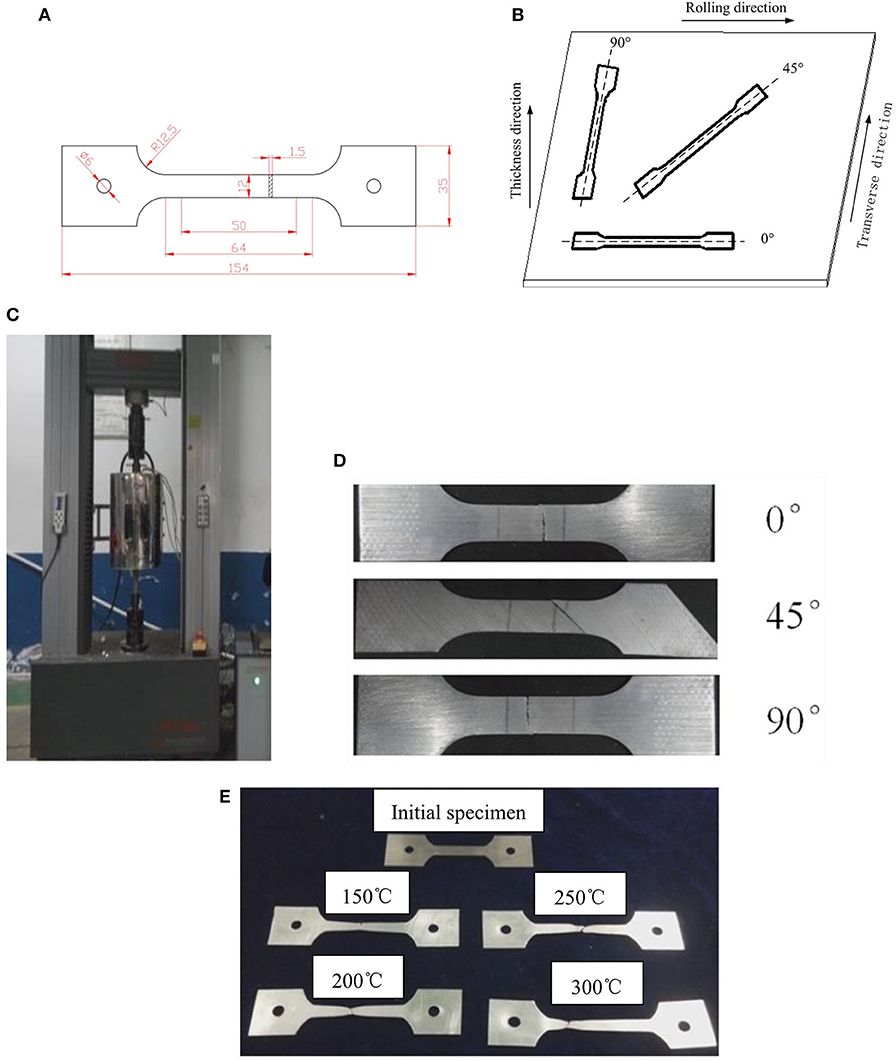
Figure 1. Diagrams and photos of tensile test: (A) dimensions of tensile specimen; (B) cutting directions of specimen; (C) the photo of tensile testing machine; (D) the photo of fractured specimen at room temperature; (E) the photo of fractured specimen in 0° direction at different temperatures.
The specimens before and after tensile testing in rolling direction are shown at room temperature and elevated temperatures in Figures 1D,E, respectively. It can be observed from Figure 1D that when the tensile temperature is below 150°C, the fracture of AZ31B magnesium alloy is brittle fracture, and when the tensile temperature is over 200°C, obvious neck shrinkage occurs at fracture points of the tensile specimens, and the fracture mode belongs to the ductile fracture. The elongation of tensile specimens in different directions at different temperatures is listed in Table 1. The elongation rates of tensile specimens in different directions increase with the rise of tensile temperatures. When the temperature increases from 150 to 300°C, the specimens in 45° direction provide the greatest elongation rate that varied from 64 to 213%.
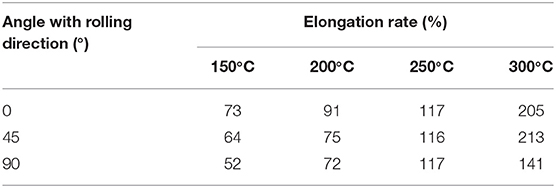
Table 1. Tensile elongation in all directions at different temperatures.
Figures 2A–C indicate true stress–strain curves of specimen at 0, 45, and 90° from rolling direction at different temperatures. When the temperatures are higher than 200°C, the stress–strain curves contain three stages. In the first stage, the stress–strain curves rise obviously, because the material mainly appears work hardening without dynamic recrystallization (DRX) at this stage. In the second stage, after the strain amount increases to critical limitation, the work hardening rate of the deformed material starts to decrease and the increase trend of stress obviously slows down. This trend will continue until reaching maximum stress, and the material internal dislocation density during this period will reach the maximum. In the third stage, the stress begins to decrease with the increase of strain because the softening effect of the material produced by DRX is stronger than work hardening.
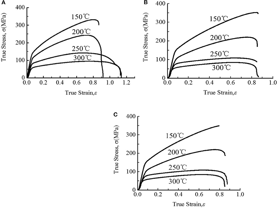
Figure 2. True stress and strain diagram in different directions at different temperatures: (A) 0° direction; (B) 90° direction; (C) 45° direction.
In Figure 2, with the increase of deformation temperature, the peak stress of the material gradually decreases. When the tensile temperatures are 250 and 300°C, the specimens are almost the same peak stress, and the obvious extensions of the specimens appear after the stress peak. The main reason for this phenomenon is that before the peak stress, work hardening leads to the increase of dislocation density, and the energy stored in the dislocation increases. After the peak stress, the energy stored in the dislocation releases gradually completely by the softening effect of the sheet caused by DRX, so the stress shows a trend of gradual stabilization.
Finite Element Modeling
The schematic of the setup for multistage SPIF is shown in Figure 3A, and the geometry model of numerical simulation and experiment is shown in Figure 3B. In the numerical simulation and physical experiments, the AZ31B blank with the length and width of 250 and 250 mm, respectively, was selected, and its thickness is 1.5 mm. The blank can be regarded as a shell in the finite element modeling. Commercial code ANSYS LS-DYNA 15.0 was used to carry out the numerical simulation of SPIF, and explicit solver was chosen. Because the numerical simulation of SPIF involves a large amount of calculation, to ensure the convergence of calculation and to improve the calculation efficiency, the friction generation heat, deformation generation heat, and temperature fluctuations of blank and tool are ignored, and the temperature in the forming process was considered constant. It is assumed that the forming tool will not produce any deformation during the forming process, so the material model of the forming tool is set as rigid body. The rotation degrees of freedom of the forming tool were restrained, and the tool trajectory data were loaded in the X, Y, and Z directions. Figures 3C,D show the displacement in X, Y, and Z directions for the four-stage SPIF, and the forming tool trajectory in the final stage is shown in Figure 3E. The mesh sizes of the forming sheet were set as 2 by 2 mm. SHELL 163 shell element was used, and the integral point number was taken 5 in the thickness direction. The mesh models of blank and tool are shown in Figure 3F.
Figure 3. Models and measuring position diagram: (A) setup of multistage SPIF; (B) dimensions of the part and illustration of measuring point positions; (C) displacements in X and Y direction with time; (D) displacement in Z direction with time; (E) the tool trajectory at final stage of the part; (F) mesh model of the blank and tool.
Because to the AZ31B magnesium alloy material belongs to anisotropic material with large deformation in multistage SPIF process, the material model selected the thickness anisotropic constitutive model here. In the case of plane stress, the model adopts Hill yield criterion, and the simplified model (Hill, 1948) is shown in Equation (1):
where R is anisotropy index in thickness direction, which is equal to ε22P/ε33P (where ε22P is the plastic strain rate in the width direction and ε33P is the plastic strain rate in the thickness direction).
A detailed study on the plastic strain ratio of AZ31B magnesium alloy sheet was carried out (Agnew and Duygulu, 2004), and the test conditions meet the requirements of this experiment of the study. Therefore, the plastic strain ratio of 2.0, 1.21, 1.1, and 1.25 at 25, 150, 200, and 250°C, respectively were cited in the simulation. The elastic modulus of AZ31B magnesium alloy at different temperatures with different transverse and longitudinal elastic modulus were investigated by Zhang et al. (2009), and these data were cited in the numerical simulation. During the whole forming process, in addition to the pressure applied by the tool on the sheet metal, the friction force is another load, and the friction coefficient is calculated by the Equation (2):
where uc is the coefficient of friction; Fd is the coefficient of dynamic friction; Fs is the coefficient of static friction; Dc is the exponential decay factor; and Vr is the relative speed.
The static friction coefficient was set as 0.2, and the dynamic friction coefficient was set as 0.1. The virtual speed was 200 times of the actual forming speed, so the exponential attenuation factor was set as 0.02.
Design of Experiment
In the process of multistage SPIF, the most important thing is to determine the number of forming stages and design the tool trajectory. Because the forming properties of different sheet metal are obviously different, the number of forming stages used in forming straight wall parts will also be different. For the straight wall parts, the number of forming stages directly determines the formability. If the number of forming stages is too small, the sheet metal will break owing to excessive thinning of the material. If the number of forming stages is too large, the forming time will increase, which is not conducive to mass production.
The numbers of forming stage from 2 to 5 are designed to investigate the influence on formability of AZ31B. Figures 4A–D indicate the forming trajectories of the part by SPIF.
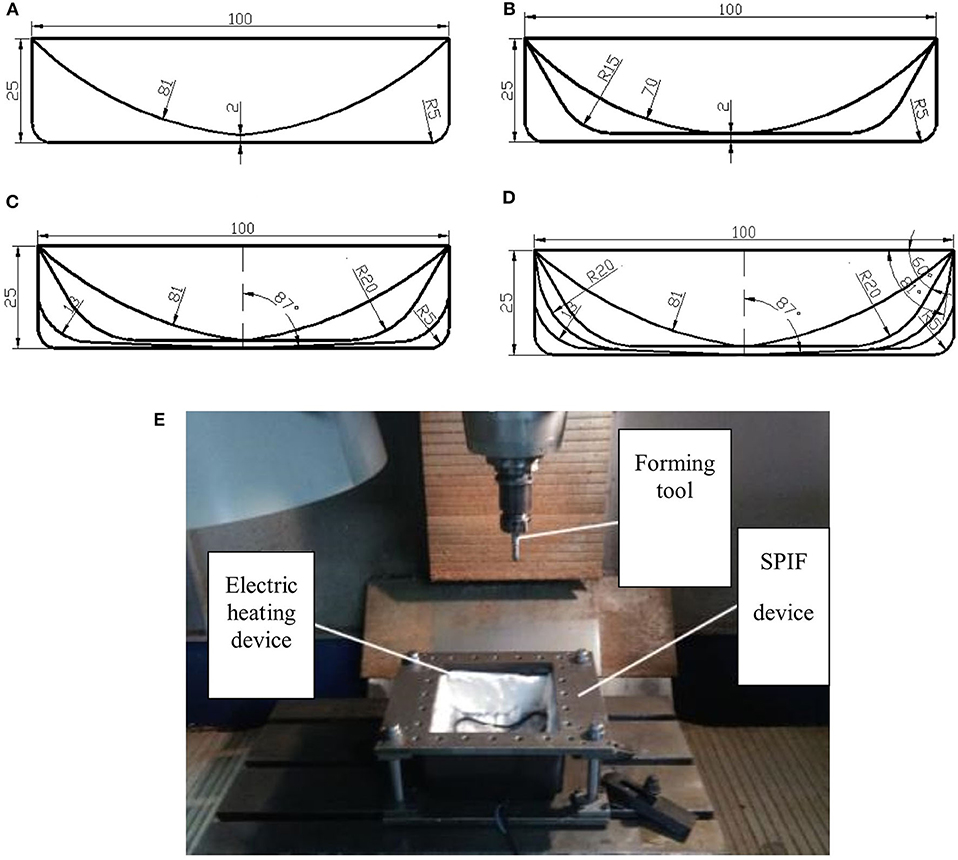
Figure 4. Schematic diagram of forming trajectory for different multistage forming and experiment equipment: (A) two-stage forming; (B) three-stage forming; (C) four-stage forming; (D) five-stage forming; (E) the experiment equipment of SPIF.
There are many factors that have influences on the formability of the parts in multistage SPIF at warm temperature, among which the most important factors are selected in the investigation, including forming temperature, feed speed, forming tool diameter, and interlayer spacing. The orthogonal test method was used to generate an L9 (34) orthonormal test table, and the combination of indexes in each test group is shown in Table 2. The thickness uniformity of formed parts serves as criteria for formability. By measuring the wall thickness at five points of the formed parts, the maximum difference value of wall thickness under different forming conditions was obtained, and the greater the value, the poorer the formability. Figure 3B indicates the positions of the measuring points. The photo of CNC milling machine and the device for the multistage SPIF experiments is in Figure 4E. To heat the blank, resistance wire was used as the heating element to make a heating device whose maximum heating power is 5 kW. A digital thermostat is used to control the on–off of the heater, to ensure a constant temperature in SPIF. The thicknesses of the test points were measured by ultrasonic thickness meter with a measuring precision of 0.01 mm and range of measure of 0.75–80 mm.
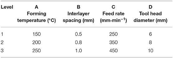
Table 2. Test factors and levels.
Results
The Effect of the Number of Forming Stages
The finite element model is used in the simulation experiment, and the simulation results are obtained. Figures 5A–D indicate the wall thickness contours of formed parts by two-stage to five-stage SPIF at the forming temperature of 250°C under the conditions of the forming tool of 10-mm diameter, interlayer spacing of 0.5 mm, feeding rate of 300 mm/min. In Figure 5A, the thinnest zone appears around point A at the bottom round corner, and the thickness is only 0.22 mm, where the distortion of meshes is obvious. The thickness distribution of the whole part is extremely uneven. The maximum wall thickness difference by the two-stage forming is 0.93 mm. As can be seen from Figure 5B, the thinnest zone of the formed part appears also at the bottom round corner, and the mesh distortion was obvious. However, the distortion significantly reduces, and the wall thickness distribution is relatively uniform compared with the two-stage forming. The average thickness of the formed part is about 0.46 mm. In Figure 5D, the minimum wall thickness of the formed part is 0.53 mm and appears at the bottom near the round corner of the part. The thickness at the bottom round corner is almost the same as that of the adjacent straight wall and the bottom zone. The average thickness is about 0.85 mm, and the maximum thickness difference is 0.57 mm.
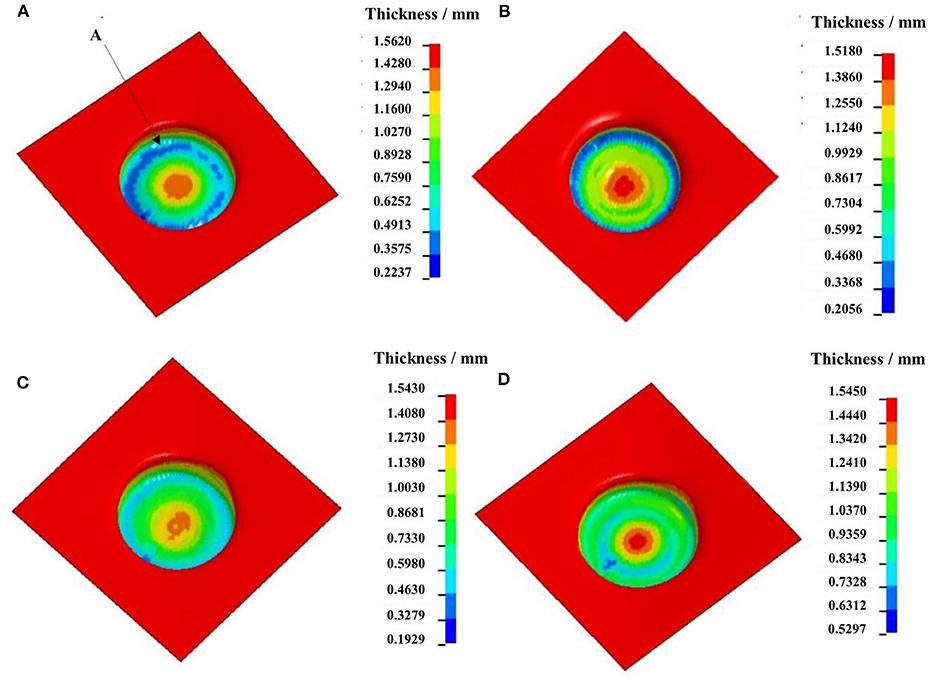
Figure 5. Wall thickness contour of formed parts by different number of forming stages: (A) two-stage SPIF; (B) three-stage SPTF; (C) four-stage SPIF; (D) five-stage SPIF.
Figures 6A–D are the wall thickness contours of the part through the first, second, third, and final stages in the four-stage SPIF, respectively. In Figure 6A, the formed workpiece with hemi-spherical shape after the first-stage forming has minimum wall thickness of 0.769 mm and maximum wall thickness of 1.501 mm. The wall thickness thinning mainly appears in the middle zone along the height direction. In Figures 6B–D, the minimum wall thickness is 0.534, 0.531, and 0.529 mm, respectively. The wall thickness at the round corner and its adjacent straight wall is almost the same, and the wall thickness of the final part has a perfect uniformity.
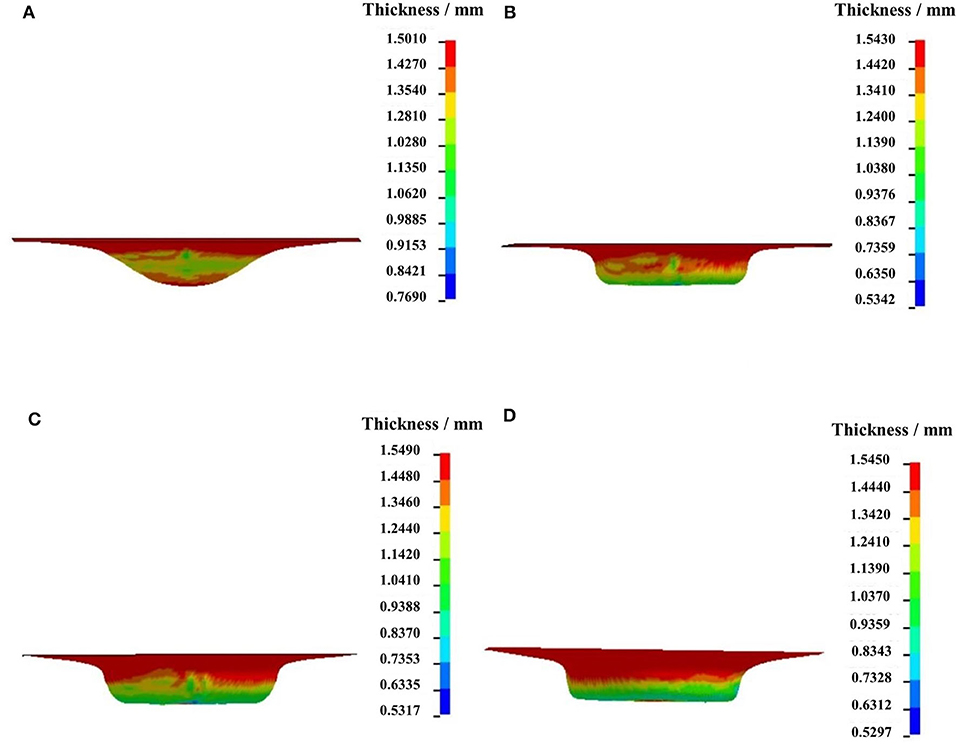
Figure 6. Wall thickness contour of part in each of the four stages: (A) the first stage; (B) the second stage; (C) the third stage; (D) the fourth stage.
Effect of Forming Temperature
Based on the numerical simulation result, Figures 7A–D indicate the thickness contours of formed parts by four stages at the forming temperature of 25, 150, 200, and 250°C under the conditions of the forming tool diameter of 10 mm, interlayer spacing of 0.5 mm, feeding rate of 300 mm/min, and forming trajectory as shown in Figure 4C. In Figure 7A, the minimum wall thickness of 0.15 mm occurred at bottom round corner of the formed part. The obvious mesh distortion occurs in the region around point A, which is the tool feed point. The thickness differences among the straight wall, bottom, and the round corner are large, and the material thickness distribution is uneven. The maximum thickness difference of formed parts is 1.35 mm. In Figure 7B, the thinnest wall thickness of 0.42 mm of formed part occurs at the bottom near round corner of the part, which is almost same as that at the bottom round corner zone, whereas the thickness of central zone at the bottom obviously increases, and wrinkling is obvious because of the material accumulation. The considerably light distortion occurs at the bottom near the round corner at 150°C, and the maximum thickness difference of the formed part is 0.85 mm. In Figure 7C, the majority wall thickness is 0.86 mm and occurs at the bottom near the round corner with the partial wall thickness of 0.69 mm. Compared with that in Figure 7B, the mesh quality at bottom near the round corner is good without any distortion. The thickness at the bottom near the round corner is almost the same as that of its adjacent straight wall, and the maximum thickness difference is 0.61 mm. In Figure 7D, wall thickness is more uniform compared with that in Figure 7C, and the maximum thickness difference is 0.53 mm without any mesh distortion.
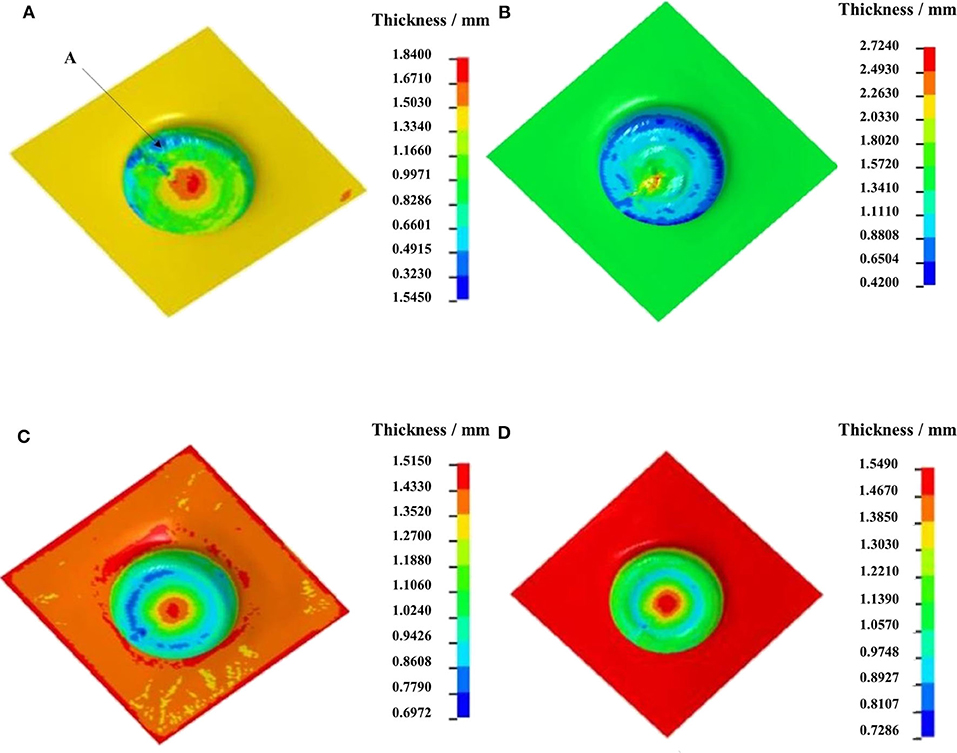
Figure 7. Wall thickness contours at different temperatures: (A) 25°C; (B) 150°C; (C) 200°C; (D) 250°C.
The Effect of Forming Tool Diameter
According to the simulation results, Figures 8A,B indicate the wall thickness contours of formed parts using forming tools with different diameters of 6 and 10 mm under the conditions of forming temperature of 250°C, interlayer spacing of 0.5 mm, feed rate of 350 mm/min, and forming trajectory as shown in Figure 4B. In Figure 8A, when the diameter of the forming tool is 6 mm, the thinnest wall thickness of the formed part appears at the bottom round corner, and its value is 0.28 mm. The thickness of the central zone at the bottom of the part is less than the initial thickness of the blank. In Figure 8B, when the diameter of the forming tool is 10 mm, the minimum thickness of 0.37 mm of the formed part still appears at the bottom round corner, and the maximum wall thickness difference is 0.76 mm.
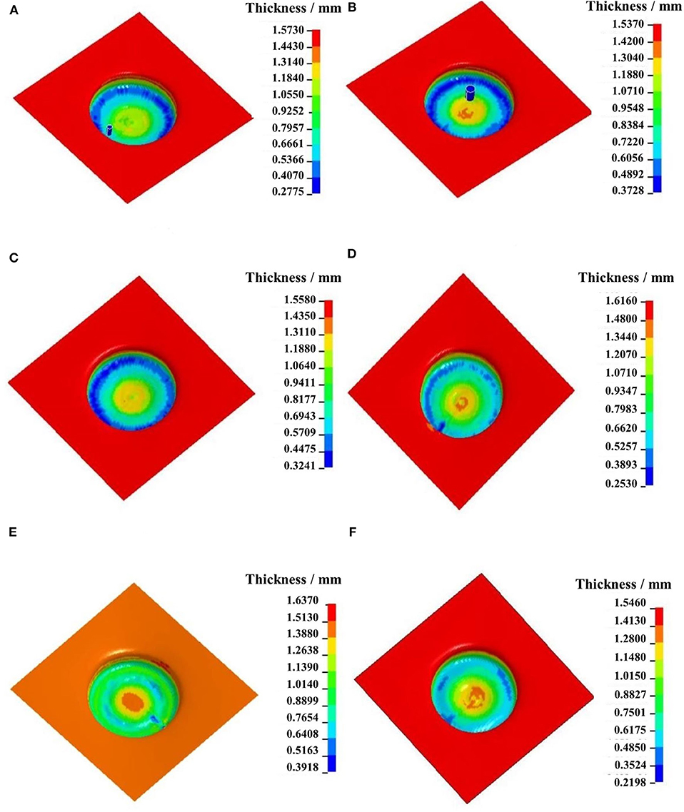
Figure 8. Wall thickness contour of formed part with different process parameters: (A) tool diameter of 6 mm; (B) tool diameter of 10 mm; (C) interlayer spacing of 0.3 mm; (D) interlayer spacing of 1.0 mm; (E) feed rate of 250 mm/min mm; (F) feed rate of 450 mm/min.
The Effect of Interlayer Spacing
Based on the simulation results, Figures 8C,D indicate the wall thickness contours of formed parts with interlayer spacing sets of 0.3 and 1.0, under the conditions of forming temperature of 250°C, forming tool diameter of 10 mm, feed rate of 350 mm/min, and forming trajectory as shown in Figure 4B. In Figure 8C, at interlayer spacing of 0.3 mm, the minimum wall thickness is 0.32 mm, and the local thickness at bottom round corner is obviously smaller than that of its adjacent zone because of the reduction of material flow performance at the bottom round corner in each forming stage. The maximum wall thickness difference is 0.67 mm. In Figure 8D, at interlayer spacing of 1.0 mm, the thickness value at the bottom near the round corner of the part is inconsistent, and the minimum wall thickness value was 0.25 mm at the down-pressing point, and the maximum thickness difference of formed part is 0.94 mm.
The Effect of Feed Rate
According to the simulation results, Figures 8E,F indicate the wall thickness contours of formed parts with tool feed rate sets of 250 and 450 mm/min, under the conditions of forming temperature of 250°C, forming tool diameter of 10 mm, interlayer spacing of 0.5 mm, and forming trajectory as shown in Figure 4B. In Figure 8E, the minimum wall thickness of the formed part is 0.39 mm, and the zone appears at the bottom near the round corner. The thickness of the bottom round corner, its adjacent straight wall, and the bottom zone of the formed part are almost the same, and its value is about 0.8 mm. The maximum thickness difference of the formed part is 0.67 mm. In Figure 8F, the minimum wall thickness of formed part is 0.22 mm, which is smaller than that at 250 mm/min. The thicknesses of most zones at the bottom near the round corner are about 0.49 mm, and the maximum thickness difference of the formed part is 0.88 mm.
The Effect of Process Parameter Combination
Based on the experiment design data in Table 2, the numerical simulations were carried out, and the wall thickness difference value Dw3 in three-stage SPIF and Dw4 in four-stage SPIF is listed in Table 3.
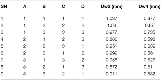
Table 3. Table of orthogonal experimental.
In three-stage SPIF process, the numerical simulated and experimental final parts using the optimal process parameters are shown in Figures 9A,B, respectively. In Figure 9A, the thinnest wall thickness appears at the bottom round corner, and the thickness is 0.38 mm. The thickness distribution of the whole part is even, and the thickness of the part reduces only at the bottom round corner. The surface of the formed part in Figure 9B is relatively smooth, but there are some small cracks in the zones at the bottom round corner, which is similar with the thinnest wall thickness zone in the simulation results. The result indicates that the straight wall cylindrical part in Figure 3A cannot be formed perfectly using AZ31B magnesium alloy sheet by three-stage SPIF. The optimal experimental parts by three-stage SPIF (on the right) and four-stage SPIF (on the left) are shown in Figure 9C.
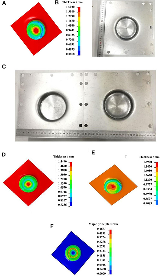
Figure 9. The numerical simulated and experimental formed parts: (A) formed part by three-stage and four-stage SPIF; (B) the simulation result of the formed part by three-stage SPIF; (C) the experiment result of the formed part by three-stage and four-stage SPIF; (D) the simulated result by four-stages SPIF before optimization; (E) the optimal simulated result by four-stages SPIF; (F) the major principle strain distribution of the formed part in neutral layer.
The influence degree of each process parameters on the inspection target value was obtained through the analysis of range (ANOR) method, and it is found that the biggest influence factor on the thickness uniformity was the forming temperature, followed by the feed rate and the diameter of the forming tool, and finally the interlayer spacing. Table 4 lists the influence degree of each factor on the inspection target.
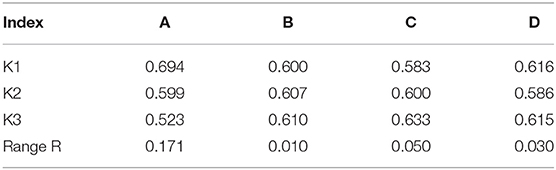
Table 4. ANOR table of process parameter in four-stages SPIF.
According to the ANOR result in Table 4, minimizing the maximum thickness difference as the optimization goal, the optimal process combination A3B2C1D2 is obtained, namely, the forming temperature of 250°C, the interlay spacing of 0.8 mm, the feed speed of 250 mm/min, and forming tool diameter of 10 mm.
The optimal parameter combination was used in the numerical simulation and experiment, and the optimal simulation results in Figure 9D prove the satisfactory thickness uniformity of the formed part with its thickness values close to 1.10 mm. At the same time, in Figure 9F, the maximum of the major principal strain of neutral layer in the formation zone is 0.4657, and major principal strains of most elements in the range at 0.25 to 0.4, which results in relative uniform wall thickness of the part. Figure 9E indicates the wall thickness contour of formed parts by test 1 in Table 2 using four-stage SPIF; the thickness uniformity is significantly worse than the optimal result, but it is better than the result using three-stage SPIF process. Figure 9D shows the high quality of formed parts with smooth surface and without obvious cracks. The deepest subsidence zone is 25.6 mm in numerical simulation, whereas the deepest subsidence zone of actual forming parts measured by venire caliper is 25.8 mm. The wall thicknesses of five points at the bottom of the part as shown in Figure 3B were measured. Table 5 lists the wall thickness deviation between the actual and simulated final parts. In Table 5, the thickness deviation between the actual formed part and simulation result is relatively small, and the maximum deviation value of the wall thickness is 8.38%, which verified the correctness of the optimal process parameters using numerical simulation method.
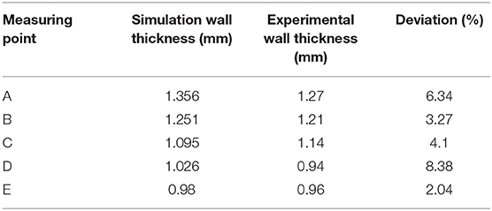
Table 5. The wall thickness error table.
Discussion
Based on the maximum thickness differences of the formed parts at different process parameters, the relationship curves are plotted by polynomial fit method in Figure 10. The relationships between maximum thickness difference and different process parameters including number of stages, forming temperature, tool diameter, feed rate, and interlayer spacing are also expressed in formula (3).
where Tmax is the maximum thickness difference; n is the number of forming stages; t is the forming temperature; s is the interlayer spacing; and r is the feed rate.
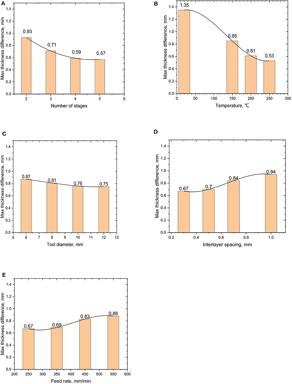
Figure 10. Relationship curves between maximum thickness difference and process parameters: (A) the influence of forming stage number on wall thickness uniformity of formed parts; (B) the influence of temperature on wall thickness uniformity of formed part; (C) the influence of forming tool head diameter on wall thickness uniformity of formed part; (D) the influence of interlayer spacing on wall thickness uniformity of formed parts: (E) the influence of feed rate on wall thickness uniformity of formed part.
It is can be seen from Figure 10A that the maximum wall thickness difference decreases obviously with the increase of the number of the stages. The reason for this largely is that the total deformation amount needs to be allocated to every forming stage, so that the more the forming stages, the smaller the deformation of each stage and the better the uniformity of the thickness of the part. However, the decrease tendency becomes very slow when the number of stages reaches 4; thus, the four-stage SPIF process is most suitable for this straight wall cylindrical part.
In Figure 10B, with the increase of forming temperature, material flow performance is significantly improved in the range of 25 to 250°C; and at the temperature of 250°C, the thickness distribution of the formed parts is the most uniform, which indicates that temperature of 250°C is suitable for forming parts of AZ31B magnesium alloy by SPIF process.
The CRSS of non-basal slip system is about a hundred times higher than that of basal slip, and {0001} dominates the slip behavior in coarse grains and a high plastic anisotropy (Barnett et al., 2004; Karewar et al., 2017). It is the reason that, although AZ31B magnesium alloy has more slip systems than FCC structures, it has poor ductility still when forming temperature is in the range of 20–150°C. According to Von Mises, to achieve a uniform deformation in the material, at least five independent slip systems should be activated. When forming temperature reaches up to the range of 200–250°C, prismatic planes , pyramidal planes {1011}, and slip systems become more activated owing to the decreasing CRSS, and the formability of AZ31B is improved obviously.
DRX is one of the vital microstructural evolution mechanisms to improve the ductility of magnesium alloy during high forming temperature (Xu et al., 2018), and fine recrystallized grains began to be found at the forming temperature of 150°C. With the increase in forming temperature, the softening effect becomes more intense gradually. Only a large number of smaller DRX grains existed between 250 and 300°C, especially along grain boundaries, in the compressive tests (Chen et al., 2018), whereas in elongated grains, twinning and nuclei formed at the beginning of DRX at 200°C, in the uniaxial tensile test (Bruni et al., 2010). Because the recrystallized tiny grains released the stress concentration during deformation, the formability of AZ31B magnesium alloy is improved obviously. When the temperature exceeds 250°C, the grain size grows rapidly with the increase of temperature. At 450°C, the grain size grows nearly three times that at 250°C, thus reaching 14.4 μm (Chen et al., 2018). The increase of the grain size causes the increase of stress concentration and the decrease of softening effect. This is the reason that the suitable forming temperature for AZ31B magnesium alloy sheet by warm SPIF is about 250°C.
According to Figure 10C, with the increase of the diameter of the forming tool, the maximum wall thickness difference of the formed parts decreases and the thickness uniformity of the formed parts is improved successively. This is because, under the premise of a certain deformation amount, the larger the diameter of the forming tools, the more the area participating in the deformation, the less the amount of deformation allocated on the unit area, and the more uniform the wall thickness of the part.
In Figure 10D, with the increase of the interlayer spacing, the maximum wall thickness difference of formed part increases. In the range of interlayer spacing from 0.3 to 0.7 mm, the maximum thickness difference of formed part rises slowly, but the whole intendancy is flat and slow. The maximum thickness difference of the formed part increases obviously when the interlayer spacing is in range from 0.7 to 1.0 mm. This is mainly because when the interlayer spacing increases, the possibility of distortion of formed sheet material will increase.
Figure 10E indicates, with the increase of feed rate, that the maximum thickness difference of formed parts increases gradually. In the range of 350 to 550 mm/min, the maximum thickness difference of formed part increases obviously, because the strain rate of sheet metal increases with the increase of feed rate.
Based on the result of numerical simulation of SPIF, the process parameters including number of forming stages, feed rate, the forming tool diameter, and the interlayer spacing affect the maximum wall thickness difference, all of which are related to the strain effect, which has an important impact on DRX. The higher the feed rate of forming tool, the shorter the forming time in SPIF and the more incomplete the DRX. In the compression experiment at 300°C, when the strain rate increased from 0.001 to 1 s−1, the volume fraction of DRX would be reduced sharply from 62 to 49.5% (Chen et al., 2018). The highly concentrated stress due to the difference in CRSS and inadequate development in DRX results in poor ductility of AZ31 alloy (Jin et al., 2017). According to numerical test result of four-stage SPIF, for AZ31B magnesium alloy sheet, the suitable feed rate is 250–350 mm/min, interlayer spacing is less than or equal to 0.8 mm, and tool diameter is bigger than 8 mm. It is suggested that in forming the deeper straight wall cylindrical part, more forming stages should be increased and at least four stages are required.
Conclusions
The straight wall cylindrical parts of AZ31B magnesium alloy formed with different process parameters of SPIF were investigated by numerical simulation, and the relationships between the maximum thickness differences and these process parameters were obtained. Based on the analysis of the result, the conclusions can be drawn as follows:
(1) The formability of AZ31 magnesium alloy sheet using warm SPIF increases with the increase of number of forming stages, forming temperature, and tool diameter while it decreases with the increase of feed rate and interlayer spacing. The favorable forming temperature is about 250°C.
(2) The process parameters that have the greatest influence on the thickness uniformity of formed parts by four-stage SPIF consist of forming temperature, interlayer spacing, feed rate, and diameter of forming tool. The forming temperature of 250°C, the interlayer spacing of 0.8 mm, the feed speed of 250 mm/min, and the forming tool of 10 mm in diameter is the optimal combination for forming the part.
(3) For forming the deeper straight wall cylindrical part, more forming stages need to designed and at least four stages are required.
Data Availability Statement
All datasets presented in this study are included in the article/supplementary material.
Author Contributions
ZA and ZG conceived and designed the study and experiment plan. ZL performed the experiments. DY and JQ built the finite element method (FEM) model and performed the numerical simulation. ZA analyzed the experimental result. ZA and JQ wrote the paper. ZA, JQ, ZL, and ZG reviewed and edited the manuscript. All authors read and approved the manuscript.
Funding
The present work was supported by the Scientific and Technological Research Program of Chongqing Science and Technology Bureau (Grant No. cstc2019jcyj-msxmX0761), the Scientific and Technological Research Program of Chongqing Municipal Education Commission (Grant No. KJQN201800731), and the Scientific and Technological Research Program of Chongqing Jiaotong University (Grant No. 16JDKJC-A005).
Conflict of Interest
ZL was employed by the company Chongqing Solid Waste Management Service Center Co., Ltd.
The remaining authors declare that the research was conducted in the absence of any commercial or financial relationships that could be construed as a potential conflict of interest.
Acknowledgments
The authors gratefully acknowledge the support from the Chongqing Municipal Education Commission, Chongqing Science, and Technology Bureau, and Chongqing Jiaotong University.
References
Agnew, S. R., and Duygulu, Ö. (2004). Plastic anisotropy and the role of non-basal slip in magnesium alloy AZ31B. Int. J. Plast. 21, 1161–1193. doi: 10.1016/j.ijplas.2004.05.018
Ahmad, R., Yin, B. L., Wu, Z. X., and Curtin, W. A. (2019). Designing high ductility in magnesium alloys. Acta Materialia 172, 161–184. doi: 10.1016/j.actamat.2019.04.019
Ambrogio, G., Filice, L., and Gagliardi, F. (2012). Formability of lightweight alloys by hot incremental sheet forming. Mater. Design 34, 501–508. doi: 10.1016/j.matdes.2011.08.024
Ambrogio, G., Filice, L., and Manco, G. L. (2008). Warm incremental forming of magnesium alloy AZ31. CIRP Ann. 57, 257–260. doi: 10.1016/j.cirp.2008.03.066
Barnett, M. R., Keshavarz, Z., Beer, A. G., and Atwell, D. (2004). Influence of grain size on the compressive deformation of wrought Mg−3Al−1Zn. Acta Mater. 52, 5093–5103. doi: 10.1016/j.actamat.2004.07.015
Bruni, C., Forcellese, A., Gabrielli, F., and Simoncini, M. (2010). Effect of temperature, strain rate and fibre orientation on the plastic flow behaviour and formability of AZ31 magnesium alloy. J. Mater. Process. Technol. 210, 1354–1363. doi: 10.1016/j.jmatprotec.2010.03.025
Chen, M.-S., Yuan, W.-Q., Li, H.-B., and Zou, Z.-H. (2018). New insights on the relationship between flow stress softening and dynamic recrystallization behavior of magnesium alloy AZ31B. Mater. Character. 147, 173–183. doi: 10.1016/j.matchar.2018.10.031
Duflou, J. R., Verbert, J., Belkassem, B., Gu, J., Sol, H., Henrard, C., et al. (2008). Process window enhancement for single point incremental forming through multi-step toolpaths. CIRP Ann. 57, 253–256. doi: 10.1016/j.cirp.2008.03.030
Dziubinska, A., Gontarz, A., Horzelska, K., and Pieśko, P. (2015). The microstructure and mechanical properties of AZ31 magnesium alloy aircraft brackets produced by a new forging technology. Proc. Manuf. 2, 337–341. doi: 10.1016/j.promfg.2015.07.059
Emmens, W. C., Sebastiani, G., and van den Boogaard, A. H. (2010). The technology of incremental sheet forming—a brief review of the history. J. Mater. Process. Technol. 210, 981–997. doi: 10.1016/j.jmatprotec.2010.02.014
Fan, G., Gao, L., Hussain, G., and Wu, Z. (2008). Electric hot incremental forming: a novel technique. Int. J. Mach. Tools Manuf. 48, 1688–1692. doi: 10.1016/j.ijmachtools.2008.07.010
Göttmann, A., Bailly, D., Bergweiler, G., Bambach, M., Stollenwerk, J., Hirt, G., et al. (2012). A novel approach for temperature control in ISF supported by laser and resistance heating. Int. J. Adv. Manuf. Technol. 67, 2195–2205. doi: 10.1007/s00170-012-4640-z
Hill, R. (1948). A theory of the yielding and plastic flow of anisotropic metals. Proc. R Soc. Lond. Series A 193, 281–297. doi: 10.1098/rspa.1948.0045
Hino, R., Kawabata, K., and Yoshida, F. (2014). Incremental Forming with Local Heating by Laser Irradiation for Magnesium Alloy Sheet. Procedia Eng. 81, 2330–2335. doi: 10.1016/j.proeng.2014.10.329
Huang, Z. H., Wang, L. Y., Zhou, B. J., Fischer, T., Yi, S. B., and Zeng, X. Q. (2018). Observation of non-basal slip in Mg-Y by in situ three-dimensional X-ray diffraction. Scripta Materialia 143, 44–48. doi: 10.1016/j.scriptamat.2017.09.011
Hussain, G., Gao, L., and Hayat, N. (2011). Forming parameters and forming defects in incremental forming of an aluminum sheet: correlation, empirical modeling, and optimization: part A. Mater. Manuf. Process. 26, 1546–1553. doi: 10.1080/10426914.2011.552017
Iwanaga, K., Tashiro, H., Okamoto, H., and Shimizu, K. (2004). Improvement of formability from room temperature to warm temperature in AZ-31 magnesium alloy. J. Mater. Process. Technol. 155–156, 1313–1316. doi: 10.1016/j.jmatprotec.2004.04.181
Jackson, K., and Allwood, J. (2009). The mechanics of incremental sheet forming. J. Mater. Process. Technol. 209, 1158–1174. doi: 10.1016/j.jmatprotec.2008.03.025
Ji, Y. H., and Park, J. J. (2008). Formability of magnesium AZ31 sheet in the incremental forming at warm temperature. J. Mater. Process. Technol. 201(1-3), 354?358. doi: 10.1016/j.jmatprotec.2007.11.206
Jin, Z.-Y., Li, N.-N., Yan, K., Wang, J., Bai, J., and Dong, H. (2017). Deformation mechanism and hot workability of extruded magnesium alloy AZ31. Acta Metallurgica Sinica 31, 71–81. doi: 10.1007/s40195-017-0681-5
Joost, W. J., and Krajewski, P. E. (2017). Towards magnesium alloys for high-volume automotive applications. Scripta Materialia 128, 107–112. doi: 10.1016/j.scriptamat.2016.07.035
Karewar, S., Gupta, N., Groh, S., Martinez, E., Caro, A., and Srinivasan, S. G. (2017). Effect of Li on the deformation mechanisms of nanocrystalline hexagonal close packed magnesium. Computat. Mater. Sci. 126, 252–264. doi: 10.1016/j.commatsci.2016.09.002
Leonhardt, A., Kurz, G., Hernández, J. V., Kräusel, V., Landgrebe, D., and Letzig, D. (2018). Experimental study on incremental sheet forming of magnesium alloy AZ31 with hot air heating. Procedia Manuf. 15, 1192–1199. doi: 10.1016/j.promfg.2018.07.369
Liu, B. Y., Liu, F., Yang, N., Zhai, X. B., and Zhang, L. (2019). Processing magnesium at room temperature. Science 365, 30-31. doi: 10.1126/science.aax9732
Liu, Z., Daniel, W. J. T., Li, Y., Liu, S., and Meehan, P. A. (2014). Multi-pass deformation design for incremental sheet forming: analytical modeling, finite element analysis and experimental validation. J. Mater. Process. Technol. 214, 620–634. doi: 10.1016/j.jmatprotec.2013.11.010
Liu, Z., Li, Y., and Meehan, P. A. (2013). Vertical wall formation and material flow control for incremental sheet forming by revisiting multistage deformation path strategies. Mater. Manuf. Process. 28, 562–571. doi: 10.1080/10426914.2013.763964
Manco, L., Filice, L., and Ambrogio, G. (2011). Analysis of the thickness distribution varying tool trajectory in single-point incremental forming. Proc. Inst. Mech. Eng. Part B J. Eng. Manuf. 225, 348–356. doi: 10.1177/09544054JEM1958
Mao, B., Li, B., Lin, D., and Liao, Y. (2019). Enhanced room temperature stretch formability of AZ31B magnesium alloy sheet by laser shock peening. Mater. Sci. Eng. A 756, 219–225. doi: 10.1016/j.msea.2019.04.054
Masood, U., Hamad, K., and Kim, J.-G. (2019). On the ductility of magnesium based materials: a mini review. J. Alloys Comp. 792, 652–664. doi: 10.1016/j.jallcom.2019.04.031
Mirnia, M. J., Vahdani, M., and Shamsari, M. (2018). Ductile damage and deformation mechanics in multistage single point incremental forming. Int. J. Mech. Sci. 136, 396–412. doi: 10.1016/j.ijmecsci.2017.12.051
Pan, H., Ren, Y., Fu, H., Zhao, H., Wang, L., Meng, X., et al. (2016). Recent developments in rare-earth free wrought magnesium alloys having high strength: a review. J. Alloys Comp. 663, 321–331. doi: 10.1016/j.jallcom.2015.12.057
Pan, H. C., Kang, R., Zeng, Z. R., Huang, Q. Y., Qin, G. W., Yang, C., et al. (2020). Mechanistic investigation of a low-alloy Mg-Ca-based extrusion alloy with high strength-ductility synergy. Acta Materialia 186, 278–290. doi: 10.1016/j.actamat.2020.01.017
Pan, H. C., Qin, G. W., Ren, Y. P., Wang, Y. Z., Nie, J. F., Haung, Y., et al. (2018). Development of low-alloyed and rare-earth-free magnesium alloys having ultra-high strength. Acta Materialia 149, 350–363. doi: 10.1016/j.actamat.2018.03.002
Ruan, L., Ezaki, S., Masahiro, F., Shen, S., and Kawamura, Y. (2016). Forming of magnesium alloy by underwater shock wave. J. Magn. Alloys 4, 27–29. doi: 10.1016/j.jma.2015.12.003
Silva, M. B., Skjoedt, M., Martins, P. A. F., and Bay, N. (2008). Revisiting the fundamentals of single point incremental forming by means of membrane analysis. Int. J. Mach. Tools Manuf. 48, 73–83. doi: 10.1016/j.ijmachtools.2007.07.004
Skjoedt, M., Bay, N., Endelt, B., and Ingarao, G. (2008). Multi stage strategies for single point incremental forming of a cup. Int. J. Mater. Form. 1, 1199–1202. doi: 10.1007/s12289-008-0156-3
Skjoedt, M., Silva, M. B., Martins, P. A. F., and Bay, N. (2009). Strategies and limits in multi-stage single-point incremental forming. J. Strain Anal. Eng. Design. 45, 33–44. doi: 10.1243/03093247JSA574
Wang, W., Huang, L., Tao, K., Chen, S., and Wei, X. (2015). Formability and numerical simulation of AZ31B magnesium alloy sheet in warm stamping process. Mater. Des. 87, 835–844. doi: 10.1016/j.matdes.2015.08.098
Xu, D., Malhotra, R., Reddy, N. V., Chen, J., and Cao, J. (2012). Analytical prediction of stepped feature generation in multi-pass single point incremental forming. J. Manuf. Process. 14, 487–494. doi: 10.1016/j.jmapro.2012.08.003
Xu, Y., Chen, C., Zhang, X., Dai, H., Jia, J., Bai, Z., et al. (2018). Dynamic recrystallization kinetics and microstructure evolution of an AZ91D magnesium alloy during hot compression. Mater. Character. 145, 39–52. doi: 10.1016/j.matchar.2018.08.028
You, S., Huang, Y., Kainer, K. U., and Hort, N. (2017). Recent research and developments on wrought magnesium alloys. J. Magn. Alloys 5, 239–253. doi: 10.1016/j.jma.2017.09.001
Yu, Z., Tang, A., Wang, Q., Gao, Z., He, J., She, J., et al. (2015). High strength and superior ductility of an ultra-fine grained magnesium–manganese alloy. Mater. Sci. Eng. A. 648, 202–207. doi: 10.1016/j.msea.2015.09.065
Zha, M., Zhang, X. H., Zhang, H., Yao, J., Wang, C., Wang, H.-Y., et al. (2018). Achieving bimodal microstructure and enhanced tensile properties of Mg−9Al−1Zn alloy by tailoring deformation temperature during hard plate rolling (HPR). J. Alloys Comp. 765, 1228–1236. doi: 10.1016/j.jallcom.2018.04.328
Zhang, H., Wang, H., Wang, J., Rong, J., Zha, M., Wang, C., et al. (2019). The synergy effect of fine and coarse grains on enhanced ductility of bimodal-structured Mg alloys. J. Alloys Comp. 780, 312–317. doi: 10.1016/j.jallcom.2018.11.229
Zhang, Q., Guo, H., Xiao, F., Gao, L., Bondarev, A. B., and Han, W. (2009). Influence of anisotropy of the magnesium alloy AZ31 sheets on warm negative incremental forming. J. Mater. Process. Technol. 209, 5514–5520. doi: 10.1016/j.jmatprotec.2009.05.012
Keywords: AZ31, magnesium alloy, sheet-metal forming, warm plastic forming, multistage forming, single-point incremental forming, optimal process parameter
Citation: An Z, Yan D, Qie J, Lu Z and Gao Z (2020) Effect of Process Parameters on Formability of a AZ31 Magnesium Alloy Thin-Walled Cylindrical Part Formed by Multistage Warm Single-Point Incremental Forming. Front. Mater. 7:151. doi: 10.3389/fmats.2020.00151
Received: 23 March 2020; Accepted: 28 April 2020;
Published: 19 June 2020.
Edited by:
Linjiang Chai, Chongqing University of Technology, ChinaCopyright © 2020 An, Yan, Qie, Lu and Gao. This is an open-access article distributed under the terms of the Creative Commons Attribution License (CC BY). The use, distribution or reproduction in other forums is permitted, provided the original author(s) and the copyright owner(s) are credited and that the original publication in this journal is cited, in accordance with accepted academic practice. No use, distribution or reproduction is permitted which does not comply with these terms.
*Correspondence: Zheng-yuan Gao, Wmhlbmd5dWFuZ2FvQGNxanR1LmVkdS5jbg==