 M. Ahmer Wadee
 Andrew T. M. Phillips
 Adam Bekele
- Department of Civil and Environmental Engineering, Imperial College London, South Kensington Campus, London, United Kingdom
The energy absorption and structural isolation performance of axially-compressed sandwich structures constructed with stiff face plates separated with an auxetic lattice core metamaterial is studied. Advances in additive manufacturing increasingly allow bespoke, carefully designed, structures to be included within the core lattice to enhance mechanical performance. Currently, the internal structure of the lattice core is deliberately disrupted geometrically to engineer suitable post-buckling behavior under quasi-static loading. The desirable properties of a high fundamental stiffness and a practically zero underlying stiffness in the post-buckling range ensure that energy may be absorbed within a limited displacement and that any transfer of strain to an attached structure is minimized as far as is feasible. It is demonstrated that such disruptions can be arranged to enhance the panel performance. The concept may be extended to promote cellular buckling where the internal lattice buckles with densification occurring at defined locations and in sequence to absorb energy while maintaining a low underlying mechanical stiffness.
1. Introduction
The conventional wisdom in terms of the perception of structural instabilities has been that they are best avoided in practice. However, with the rapid emergence of nonlinear mathematics, computational power, alongside numerical, and manufacturing techniques, the exploitation of the geometrically nonlinear range is becoming increasingly feasible for a wider range of applications (Reis, 2015; Champneys et al., 2019). Of course, in the field of thin-walled structures, the naturally stable post-buckling of plates has been exploited since the 1940s due to the pioneering work of, amongst others, von Kármán et al. (1932) and Winter (1947). More recently, in the fields of mechanical and aeronautical structures, instabilities have been used in so-called smart shape-morphing materials and structures that switch from one geometric form to another under particular loading ranges (Arena et al., 2018); this also has significance in the field of energy harvesting (Hu and Burgueño, 2015). In the design of metamaterials, the nonlinear behavior of their internal structure can result in some rather unexpected but potentially exploitable features (Bertoldi et al., 2017)—this is especially the case for auxetic materials that are designed to have a negative Poisson's ratio (Masters and Evans, 1996; Bertoldi et al., 2009; Grima et al., 2009; Körner and Liebold-Ribeiro, 2015; Hunt and Dodwell, 2019).
Instabilities may be readily exploited in applications involving energy absorption or structural isolation. Critically important structures, which require protection from, for instance, impact or blast, can be shielded by attaching protective sacrificial structures that absorb the energy of the hazardous load while imparting stresses that are insufficient to cause damage to the more important structure. For such sacrificial structures to be practically effective, they need to have certain properties: primarily, a low structural stiffness is necessary (Schenk and Guest, 2014). This is because low stiffness leads to diminished stress propagation and has been shown to be effective in isolating sacrificial structures from a more important one (Virgin and Davis, 2003). Although a very soft (intrinsically low stiffness) material with a relatively high yield stress would technically be able to perform this task, the load vs. deflection response graph depicted in Figure 1A, demonstrates that the required structural displacements, characterized by δ0 in the graph, providing the desired energy absorbency could be excessively large. This would render the soft material to be practically unsuitable in terms of the necessary thickness of material to facilitate the deformation required to absorb the energy efficiently. Therefore, low structural stiffness needs to be combined with a high load-carrying capacity; this is an area where post-buckling behavior of structural components may be exploited since structures that undergo instabilities tend to have at least two mechanical phases under compressive loading. The first phase being the pre-buckling (fundamental) behavior, where the stiffness is relatively high and the required load-carrying capacity is established. The second being where the post-buckling stiffness may be relatively low, idealized in the mechanical load vs. deflection response depicted in Figure 1B. Subsequent phases could include further elastic instabilities causing so-called cellular buckling (Hunt et al., 2000), material inelasticity or even fracture. In combination, unlike the aforementioned soft material, the mechanical phases associated with such elastic behavior would significantly reduce the amount of deflection required to absorb a given amount of energy and a commensurate reduction in the amount of material necessary to perform the task successfully.
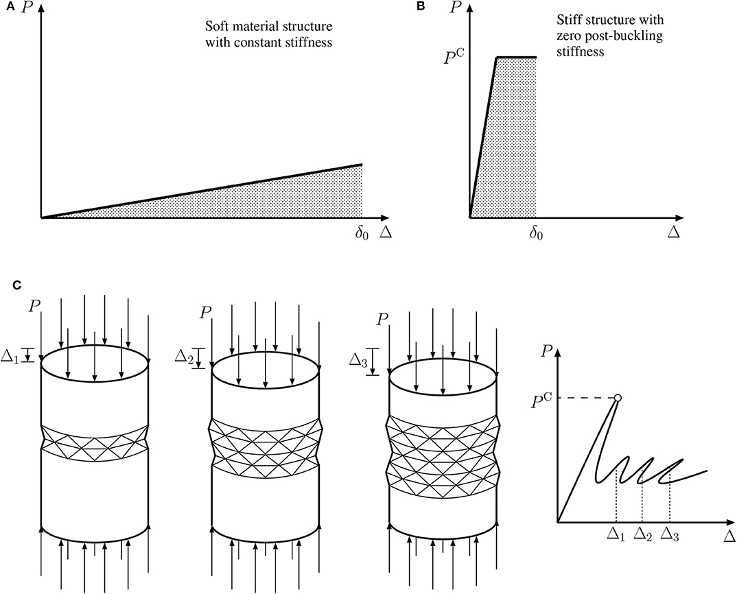
Figure 1. (A,B) Example mechanical responses showing load P vs. deflection Δ relationships with equal-sized shaded areas and δ0 marking the corresponding deflection representing strain energy absorbed for structures made from: (A) a soft linear elastic material; (B) a structure made from a stiffer material with a critical buckling load PC and a zero stiffness post-buckling response. (C) Sequential cellular buckling response of an elastic axially compressed cylindrical shell (Hunt et al., 1999).
A finite element study using the commercial software ABAQUS (ABAQUS, 2017) is presented concerning the performance of lightweight sandwich structures under axial compression which is assumed to be quasi-static. Unlike in conventional sandwich panels where stiff face plates are separated by a softer core material comprising either a foam or honeycomb-type material, a lattice core metamaterial is assumed presently. While the mechanical response of sandwich panels with conventional cores has been studied in depth (Allen, 1969; Gibson and Ashby, 1999), advances in additive manufacturing potentially allow bespoke features to be included within the core metamaterial that may be used to enhance mechanical performance. In the current work, which extends a recent pilot study (Wadee et al., 2019), the arrangement of the core metamaterial is deliberately disrupted from its periodically repeating lattice structure by introducing bespoke geometric features, known presently as “disruptions,” which promote responses suitable for energy absorption or structural isolation applications. Unlike conventional structural design, where the principal concern is to maintain strength and stiffness of the component even after any instability, the desired properties currently are to combine a reasonably high load-carrying capacity, and a generally diminished post-buckling stiffness. It is demonstrated that certain disruptions have greater efficacy than others and these can be explained by investigating the local responses within the core lattice and the interaction with the face plates. Moreover, mechanical responses may be tuned to produce the desired load—deflection behavior. An auxetic unit cell is studied initially and the obtained results are used to select the configuration of a sandwich core lattice with a uniform cellular arrangement. The results from studying the uniform lattices demonstrate that the load-carrying capacity can be enhanced but without necessarily enhancing the post-buckling behavior. However, subsequent inclusion of disruptions within the lattice at various locations by changing the auxetic cellular orientations are shown to facilitate more favorable post-buckling behavior without significantly affecting the load-carrying capacity. The study demonstrates that it is potentially feasible to arrange a bespoke lattice core in a sandwich panel to provide properties that are desirable for structural isolation and energy absorption applications.
2. Cellular Buckling
Classically, buckling instabilities involve a distinct, individual, eigenmode being triggered at a bifurcation point with a particular critical buckling load within the elastic range. Subsequently, this buckling mode is amplified nonlinearly in the post-buckling range until ultimate collapse occurs. If the buckling response is inherently unstable, the archetypal example being an axially-compressed cylindrical shell, ultimate collapse occurs at the instant the instability is triggered and is associated with a high degree of imperfection sensitivity and localization in the deformation. However, if the buckling response is inherently stable, the archetypal example being an axially-compressed flat plate, the initial mechanical response within the elastic range is associated with an insensitivity to imperfections and periodicity in the deformation. Ultimate collapse of stable systems usually involves either the subsequent overstressing of the material or a secondary instability being triggered within the elastic range, or perhaps a combination of the two. The loss in stiffness associated with material overstressing, or a secondary elastic instability, transforms the mechanical behavior from stable to unstable and the observed periodicity to localization.
Deformation beyond the ultimate load on a locally unstable equilibrium path, regardless of the stability or otherwise of the initial bifurcation, can lead to some intriguing behavior being observed in systems where there is capacity for the response to restabilize. In the present context, “restabilization” is defined as the post-buckling stiffness of the system being restored to a positive value after it was initially negative on or very soon after triggering the critical bifurcation. This is distinct from structures that return to their fundamental equilibrium state from a post-buckled state under certain loading conditions, which has been termed restabilization in some recent work on flexible rods (Bigoni et al., 2014; Bosi et al., 2016). The localization of the deformation may halt and begin to redistribute itself sequentially. This is often observed in the mechanical response as a series of snap-back instabilities that mark individually where deformations grow, halt and spread in sequence. This has been termed cellular buckling (Hunt et al., 2000; Budd et al., 2001), owing to the buckling deformation being triggered in cells, or snaking (Woods and Champneys, 1999; Burke and Knobloch, 2007), which reflects the profile of the equilibrium diagram. This type of behavior has been observed in several different structural systems such as cylinders (Hunt et al., 1999), sandwich panels (Hunt et al., 2000), stiffened plates (Wadee and Farsi, 2014), thin-walled I-section (Wadee and Bai, 2014), and angle struts (Bai et al., 2017), and beams (Wadee and Gardner, 2012) alongside prestressed stayed columns (Yu and Wadee, 2017). It has also been observed in confined layered structures where kink-bands are formed and propagate (Wadee and Edmunds, 2005).
Figure 1C shows a sketch of the well-established sequential response of a compressed elastic cylindrical shell (Hunt et al., 1999), where the number of localized buckling cells increases with the axial deformations. The triggering of each cell is marked on the equilibrium diagram as the locations of highly unstable snap-backs, the first one being particularly severe. The severity of the initial instability is not necessarily a positive feature for energy absorption applications since the drop in load-carrying capacity inherently reduces the absorption capacity of such a component. However, the underlying small stiffness in the far-field post-buckling range is potentially very encouraging for structural isolation applications. Hence, the combination of a limited initial snap-back instability and a small underlying post-buckling stiffness would provide a superior response for the applications that are discussed currently. This is the aim of the current work and since sandwich panels are well-known to be extremely efficient load-carriers, there is an opportunity to engineer the core material to induce the cellular buckling mechanism favorably for this combination of applications.
3. Sandwich Panels Under Axial Compression
Sandwich structures generally comprise two stiff face plates separated by a softer core material; Figure 2A depicts a typical panel under axial compression. However, the core material, which is normally some kind of cellular solid made from an intrinsically less dense foam material may be replaced by a lattice arrangement. This arrangement, comprising an identical material to the face plates, would reduce the overall relative density of the structural component making it similarly effective as a conventional sandwich panel. Moreover, the separation of the stiff face plates using the lattice provides significant bending stiffness without a commensurate increase in self-weight.
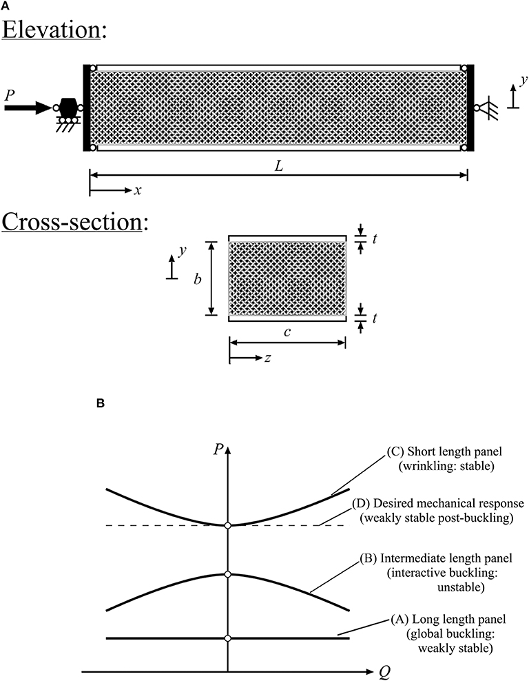
Figure 2. (A) Axially compressed simply-supported sandwich panel (a strut in this case) of length L, breadth c, core depth b and face plate thickness t. (B) Schematic of equilibrium paths of load P vs. a reference deflection Q for sandwich panels of various lengths.
As discussed in the introduction, for effective energy absorption and structural isolation characteristics, the features combining a high load-carrying capacity and a diminished post-buckling stiffness are desired. To achieve both initially requires the consideration of the basic candidate geometries that could realistically achieve these objectives. Long panels tend to be vulnerable only to global (Euler-type) buckling, which is well-known to have a weakly stable post-buckling characteristic, but also have a low critical buckling load since that is inversely proportional to the length to depth (L/b) ratio, see graph (A) in Figure 2B.
As the sandwich panel length L is reduced, there is a range where the buckling loads for the global (Euler-type) mode and the wrinkling local mode become similar (Hunt et al., 1988; Hunt and Wadee, 1998; Wadee et al., 2010). This tends to promote nonlinear local–global mode interaction and the post-buckling behavior tends to become unstable (van der Neut, 1969; Shen and Wadee, 2018) and the panels become sensitive to imperfections (Wadee, 2000), see graph (B) in Figure 2B. Such a system would have an underlying negative stiffness and would naturally limit the energy absorption capacity.
If the length is reduced still further, the critical buckling load increases and the behavior becomes dominated by the local wrinkling of the face plates; the post-buckling behavior for such conventional panels is relatively stable, see graph (C) in Figure 2B. Although this may be desirable in many cases, for energy absorption or structural isolation applications, the stable post-buckling behavior would facilitate undesirable stress propagation across its boundary. However, by altering the arrangement of the core material, this potentially can be changed to introduce more favorable behavior with a negligible stiffness, as depicted in graph (D) in Figure 2B.
3.1. Cellular Buckling in Sandwich Structures
As indicated earlier, during a pilot study on axially-compressed sandwich structures it was demonstrated that the properties of the core material could introduce cellular buckling behavior (Hunt et al., 2000). Although the initial localization induces highly unstable behavior, the subsequent spreading of the deformation restabilizes the elastic mechanical response somewhat, which potentially allows further energy to be absorbed by the panel so long as it remains largely elastic.
More conventional core materials made with foams or honeycomb structures (Gibson and Ashby, 1999) tend to have a distinct three-stage constitutive behavior under compression (see Figure 3) with an approximately linearly elastic part, a softening part with a much reduced stiffness, which is associated with buckling of the internal microstructure where the cell walls begin to resist loads under a combination of axial (often termed “membrane”) and bending stresses. This is followed by subsequent densification where the buckled microstructure cannot deform further owing to the presence and stiffness of neighboring cells and the original stiffness recovers. It is this characteristic sequence of destabilization and restabilization in combination with local–global mode interaction (Hunt and Wadee, 1998) that has been attributed to cause potential cellular buckling in sandwich panels. However, that study considered intermediate length panels so the equilibrium response was shown to have an underlying negative post-buckling stiffness, which would be unsuitable for energy absorption and structural isolation applications. Therefore, in the current study, shorter panels are considered such that their post-buckling stiffness becomes practically negligible.
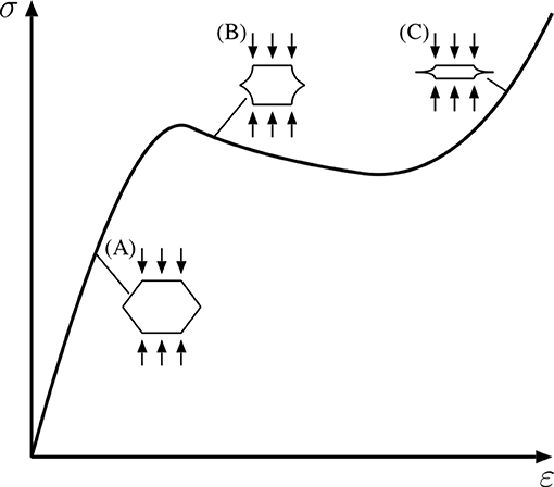
Figure 3. Stress σ vs. strain ε behavior of conventional cellular core materials under compression. (A) Small deflection linear behavior; (B) elastic buckling of cell walls causing destiffening; (C) restiffening from cell densification.
3.2. Lattice Cores
With the increasing accessibility of additive manufacturing, commonly known as 3D printing, it is now possible to engineer bespoke properties into materials that were hitherto difficult to realize. In previous work, the face plates and core materials were constructed from fundamentally different materials. However, in the current study it is assumed that the sandwich panel production process would be additive manufacturing, hence the face plates and cores would be manufactured from the same material with the core being constructed as a lattice. In the current context, bespoke features within the lattice are introduced to produce desired behavior. For instance, the prevention of immediate localization of the wrinkling mode is desired such that instantly catastrophic failure is avoided. This is because localization is a fingerprint of a strong and violent instability where the load-carrying capacity is significantly reduced. This can be avoided by spreading the wrinkling deformation throughout the structure by engineering a bespoke core, where axial and bending stresses are introduced within the network of lattice elements, to resist the internal deformation that effectively reproduces the stabilizing effect of densification [see point (C) in Figure 3]. Auxetic materials have features that promote densification since under compression their “volume” effectively reduces. This is achieved because such materials have an effectively negative Poisson's ratio that is introduced by having a re-entrant (concave) internal structure; some examples of re-entrant structures that produce auxetic mechanical behavior are shown in Figure 4 (Masters and Evans, 1996; Grima et al., 2009). Although there has been considerable work on this topic since the 1990s, in terms of the type of geometries that induce auxetic mechanical behavior, presently the arrowhead geometry is used within the models, as shown in Figure 4B. The mono-symmetric characteristic of the arrowhead cell is exploited currently; the mechanical response of the unit cell and lattice with this arrangement has been studied in detail (Brighenti et al., 2016).
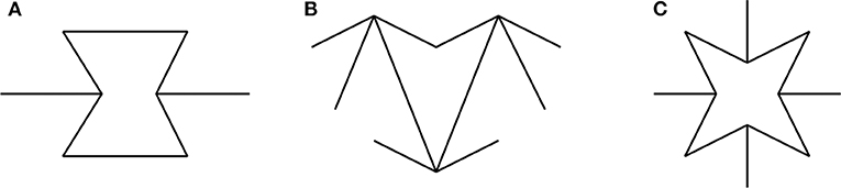
Figure 4. Some examples of material internal structures providing auxetic behavior: (A) hexagonal hourglass; (B) arrowhead; (C) octagonal star.
Apart from the negative Poisson's ratio, auxetic materials are known also to have an enhanced shear modulus. In earlier work on sandwich structures, it has been demonstrated that an increased core shear modulus can strengthen a panel against face–core wrinkling (Wadee and Hunt, 1998). Therefore, judicious use of auxetic structures in a core lattice is postulated to provide a potentially enhanced elastic post-buckling range with greater elastic deformation capacity. This is in contrast to conventional cellular materials where permanent deformation accompanies the nonlinear material response simultaneously.
4. Methodology
4.1. Finite Element Modeling
To model the behavior of the sandwich panels, a series of linear elastic two-dimensional, geometrically nonlinear, finite element (FE) models have been formulated within the commercial code ABAQUS. A network of beam elements is used to simulate a simply-supported sandwich strut with a lattice core that is under axial compression with a load that is assumed to be quasi-static, as shown in Figure 2A. Quadratic Timoshenko beam elements (B22) are used to model both the face plates and the core lattice since these have been demonstrated to provide an efficient yet accurate representation of the deformation in previous studies (Wadee et al., 2010). The expected deflected shapes were modeled using multiple elements for each structural member and a mesh convergence study revealed that four elements per structural member were sufficient. On the models without central disruptions, a small perturbation is introduced to the geometry of the face plate at midspan such that wrinkling and potentially global buckling can be modeled since this bypasses any bifurcations that may cause convergence issues.
A set of cases comprising different core lattice configurations including purely uniform auxetic cores and a number of separate cores with disruptions are studied. The rationale is that uniform cores are routinely made and it is worth investigating how disruptions in the geometry affect the mechanical response in terms of ultimate strength, post-buckling stiffness and the extent of deformation. In each case, the properties for the beam elements are specified to be uniform with a Young's modulus E = 2 GPa, which is a typical value for nylon used in selective laser sintering (SLS) (Bourell and Beaman, 2005). A rectangular solid cross-section with a defined thickness for a given lattice arrangement and a constant breadth c (see Figure 2A and c is purely a common factor currently) of 1.5 mm is used for the internal core elements. For the face plates, the cross-section is a solid square of side length 1.5 mm; this latter figure equating to the thickness t, as defined in Figure 2A. The total depth of the panel (b+2t) is kept constant at 100 mm; the length L is also kept constant at 350 mm. These dimensions are designed such that wrinkling is critical for the panel with the global buckling load being considerably higher. One parameter that is maintained to be constant within the numerical study is the relative density of the core lattice, which is defined as the ratio of the mass of the core lattice to the mass of a solid core constructed from the same material, such that meaningful comparisons can be made. This is achieved by adjusting the thickness of the beam elements that comprise the lattice to maintain a constant mass.
The presented work initially examines the mechanical behavior of various unit cell arrowhead configurations with different inclination angles. This is used to establish a preferential configuration for the study of uniform lattice cores leading to investigations regarding the effects of disruptions along the symmetric axes of these panels. Finally, a discussion is presented on an enhanced core arrangement that amalgamates the outcomes of the initial models with disruptions.
4.2. Arrowhead Unit Cell
An arrowhead unit cell under compression in both the vertical and horizontal directions, as shown in Figure 5, is initially investigated. The boundary conditions are such that the bottom left corner is pinned, hence all translational degrees of freedom are restrained, while the lower right support is on a roller allowing horizontal displacement only. The members of length l1 and l2 are inclined to the horizontal by angles θ and α, respectively, as shown in Figure 5A. For each loading case, the displacement arising from the load P is defined as δ. In the first loading case, depicted in Figure 5B, opposing vertical loads are applied at the vertices as shown. A factor n is included to the load applied to the lower vertex to establish the effects of unequal loading scenarios. For the case depicted in Figure 5C, the load is applied horizontally to the bottom right roller support as shown.
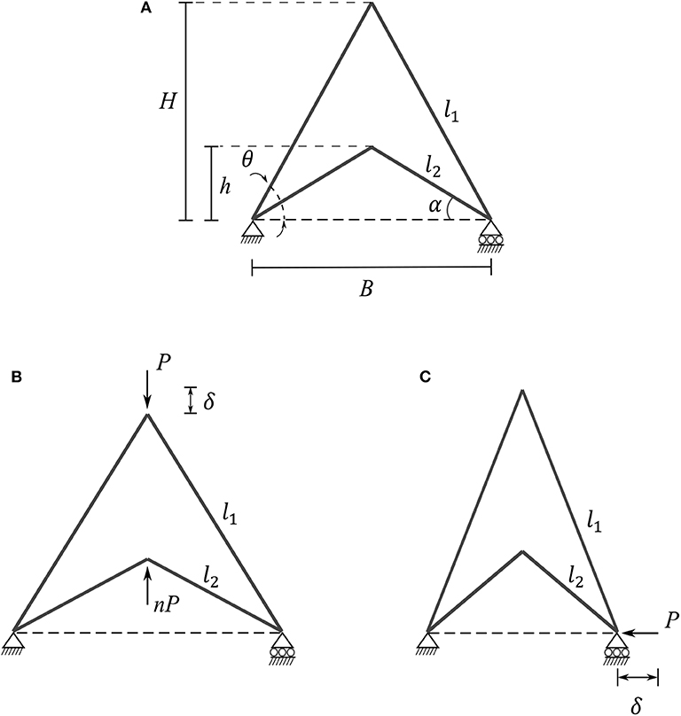
Figure 5. Unit cell of the arrowhead geometry under two different loading conditions. (A) Definitions of angles and lengths of the unloaded cell; (B) two opposing vertical loads P and nP applied at the top and bottom vertices and (C) a horizontal load P applied at the roller support.
To establish the effects of changes to the inclination angles, four arrowhead unit cells with varying angles θ and α are investigated, as shown in Figure 6. For each model, the angle θ is chosen to be twice the value of α and the width B is kept at a constant value of 14 mm which subsequently alters the height H of the cells alongside the lengths l1 and l2. Since these angular variations modify the area coverage of each cell, the thickness t of the cellular members have been altered (see Table 1) to maintain a constant relative density of 0.3, which is defined as an upper limit for a cellular solid (Gibson and Ashby, 1999).
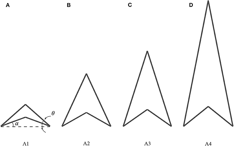
Figure 6. Arrowhead cells with respective varying inclination angles θ and α with (A) A1: 45.0°, 22.5°, (B) A2: 60.0°, 30.0°, (C) A3: 70.0°, 35.0°, and (D) A4: 80.0°, 40.0°, respectively. The breadth B is kept constant for all cases hence there are variations in height.
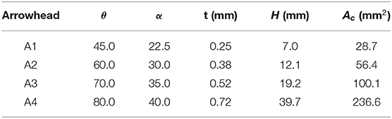
Table 1. Inclination angles θ and α, thickness t, height H, and enclosed area Ac values for each arrowhead unit cell type, A1–A4.
4.3. Panels With Uniform Cores
When studying the effects of the aforementioned arrowhead configurations within sandwich panel cores, it is imperative first to understand their behavior as a uniform, periodically repeating, lattice structure within a sandwich strut arrangement. Figures 7A–C present examples of such uniform arrowhead cores orientated in two orthogonal directions, horizontally and vertically: cases “AH” and “AV,” respectively, with cell member inclination angles θ = 60° and α = 30°. The specific angles for θ and α being chosen since they provided desirable properties from the study of the unit cell. A third case “AVVS” is also introduced by modifying the vertically orientated arrowhead as seen in Figure 7C.
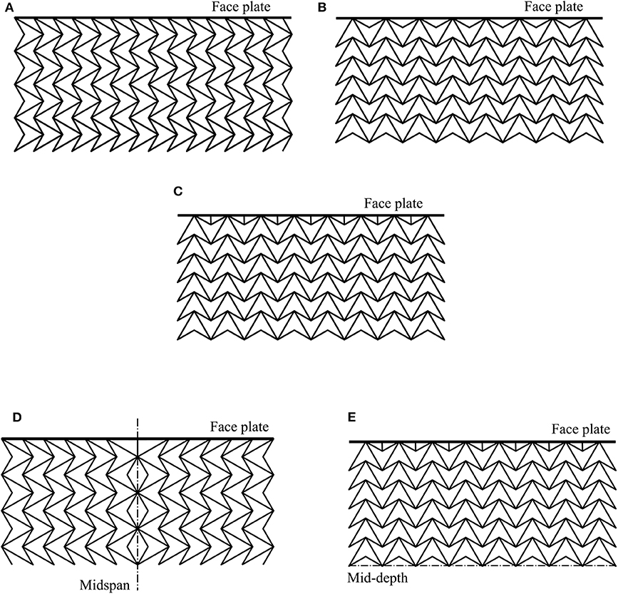
Figure 7. Lattice cores with uniform geometries: (A) case AH: “Arrowhead Horizontal”; (B) case AV: “Arrowhead Vertical”; (C) case AVVS: “Arrowhead Vertical with Vertical Struts” at the face plates. Lattice cores with disruptions: (D) AHBFMS: horizontal arrows with back facing cells along the midspan line of symmetry and (E) AVBFVS: vertical arrows with back facing cells along the mid-depth line of symmetry. Note that only a portion of the panels are depicted.
4.4. Panels With Disruptions
Further to the study of the uniform cores, disruptions are introduced by modifying the AV and AH panels. The updated configurations are: “AHBFMS” and “AVBFVS,” where “BF” denotes a “back facing” cell disruption with subscripts “MS” and “VS” denoting the presence of “middle struts” and “vertical struts,” respectively. The arrangement AHBFMS has horizontally facing arrows that are symmetric about the central midspan with a middle strut joining onto the top and bottom face plates from the edge cell. Arrangement AVBFVS has vertically facing arrowheads that are symmetric along their back faces along the mid-depth and with vertical struts near the face plates as in the case AVVS; both are shown in Figures 7D,E. Initial studies are conducted on lattices of these forms with individual cells having inclination angles θ = 60° and α = 30°, selected for the same reasons as before.
5. Numerical Results
5.1. Unit Cell Behavior
Figure 8A shows the equilibrium paths for the four different unit cell arrangements listed in Table 1 subject to vertical loading. It is
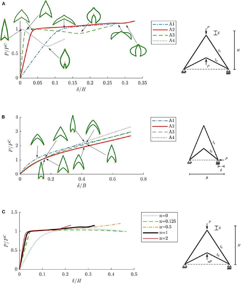
Figure 8. Normalized load vs. normalized axial end-shortening responses for unit cell models. (A) P/PC vs. δ/H for arrowhead cells with varying inclination angles under vertical compression loading. (B) P/PC vs. δ/B for arrowhead cells with varying inclination angles under horizontal compression loading. (C) P/PC vs. δ/H for the arrowhead cell A2 with inclination angles θ = 60° and α = 30° with varying bottom vertical load nP where n = {0, 0.125, 0.5, 1, 2}.
noteworthy that the cell elements bend immediately under loading and there are some differences in the initial stiffness of the cells. This is largely owing to the variations in thickness between the cellular members. Since rectangular beam sections have been selected with constant depth and differing thicknesses, the beam cross-section radius of gyration . The quantity Rg estimates the ratio of the bending to axial stiffness of the cell, where Ib is the second moment of area about the beam bending axis equal to (ct3)/12 and Ab is the beam cross-sectional area equal to ct. Since it is demonstrated that Rg is proportional to the beam thickness t, an increase in t leads to an increase in the relative bending stiffness, shown by the increase in the initial slope in the graphs for models A1–A4, as shown in Figure 8A. Moreover, as the inclination angles are increased, the cell element lengths also increase. It is well-known that strut buckling loads reduce rapidly with increasing length, therefore the drop in the load at which the initial instability is triggered from cases A2–A4 is expected.
However, the post-buckling stiffness behavior depends on the initial inclination angles. The shallower cells with the smaller inclination angles i.e., A1 and A2 have a positive, yet near zero, post-buckling stiffness value. Note that all the equilibrium paths have been curtailed at the point where the upper and lower vertices of the arrowhead touch since two-dimensional Timoshenko beam elements B22 do not allow beam-to-beam contact to be modeled. Beyond a certain inclination angle, the initial post-buckling stiffnesses begin to decrease below zero, as shown in cases A3 and A4. A modest recovery of stiffness is observed in cases A2–A4. This corresponds to the inclined elements becoming more vertical and hence mobilizing their axial, as opposed to bending, stiffness; this is often referred to as “cable” or “membrane” action. For case A1, the upper and lower vertices touch prior to significant membrane action being observed.
Compression testing in the horizontal direction was also conducted on the four arrowhead unit cells with the arrangement depicted in Figure 5B. The equilibrium paths for these models are shown in Figure 8B. For this loading case, case A1 with the shallowest inclination angles, provides greater axial stiffness than the other cases. It is also noteworthy that the remaining cases show only minimal differences in their stiffness and equilibrium paths.
A further study is presented that examines the effects of unequal loading in the vertical direction. For this, the model A2 with inclination angles θ = 60° and α = 30° is chosen and the equilibrium paths for five different n values, where n is the factor by which the vertically upward load is varied, are shown in Figure 8C. This study was conducted to establish how adjacent cells with skewed directionality and hence an uneven compression force would impact the behavior of cells within a larger array. Again, the curves are all curtailed at the point where the upper and lower beams first touch. When the lower load is removed (n = 0), the system resembles the well known case of a simple arch (Thompson and Hunt, 1973) where, if the entirety of the curve were displayed, a limit point and snap-through response would be observed. However, as soon as n assumes a non-zero value, minimal changes are observed between the equilibrium paths. The slight variations lie in their post-buckling stiffnesses. When a non-zero n is introduced, the outward lateral displacement at the roller support is restricted by the lower force which, in turn, increases the stiffness of the system and also the effective buckling load when compared to the n = 0 case. For small values of n, however, with the upwards vertical load being relatively small, generally leads to the upper inclined members instantly bending which result in the cell attaining a low post-buckling stiffness. As the value of n is increased, the post-buckling stiffness gradually increases with the reduction in the bending of the upper members and an overall increase in the bending stiffness of the cell. Lastly, when n>1, the secondary restiffening phase coincides with the lower inclined elements being more vertical and resisting the load primarily through membrane action at an earlier stage in the deformation process.
5.2. Behavior of Panels With Uniform Cores
Figure 9A shows the load vs. end-shortening relationship for sandwich panels with uniform lattice cores. It is evident that the orientation of the geometry plays a major role in the load-carrying capacity of the sandwich panel. The AH lattice has a practically double load-carrying capacity to the AV counterpart (see Table 2). This significant difference in capacity is principally dictated by the tighter spacing of the lattice adjacent to the face plates; in case AH, the edge nodes of the arrowhead that meet the face plates are closer together due to the proximity of adjacent cells when arranged horizontally. The face plates between these adjacent nodes act akin to a pin-ended strut with the effective length Le being the distance between these nodes (see Figure 9A). Since the buckling load for a pin-ended strut is proportional to , the face plates for case AH buckle at a higher load than in case AV. In both cases, the post-buckling stiffness is close to zero.
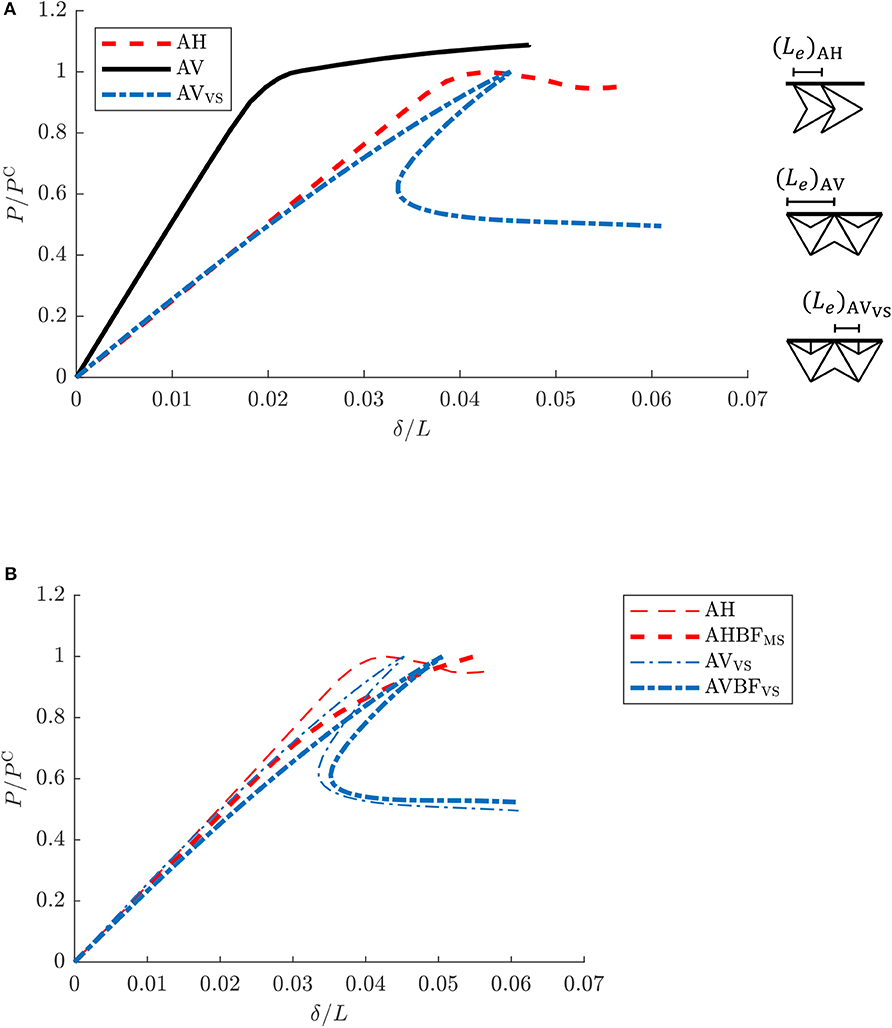
Figure 9. Normalized load vs. normalized axial end-shortening behavior for a set of sandwich panels. (A) P/PC vs. δ/L for the set of uniform cores: AH, AV, and AVVS. (B) P/PC vs. δ/L for the cores without disruptions: AH and AVVS; alongside the cores with disruptions along the midspan or mid-depth: AHBFMS and AVBFVS, respectively.
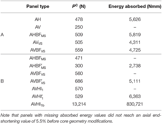
Table 2. Critical buckling loads and absorbed energies from the panel cases with (A) uniform cores and ones with disruptions composed of cells with inclination angles θ = 60° and α = 30°; and (B) panel cases with further disruptions and modified inclination angles θ = 45° and α = 25° all evaluated at a common normalized axial end-shortening (δ/L) value of 5.5%.
In case AVVS, the length Le between adjacent connections is reduced by introducing vertical struts that join the face plates additionally to the cells, thereby increasing the wrinkling load. Although the load-carrying capacity of the vertically orientated lattice was tuned through modifications at the face plate–core interface, the post-buckling behavior of AVVS shows a violently unstable snap-back response before restabilizing at a significantly lower residual load. These results necessitate studying further disruptions in both the AVVS and AH configurations to produce more appropriate arrangements for the required characteristics suitable for energy absorption and isolation applications.
5.3. Behavior of Panels With Disruptions
The load vs. axial end-shortening relationships for axially compressed panels without and with disruptions, discussed in section 4.4, are given in Figure 9B. In both cases, comparisons are drawn between the models with disruptions and their uniform core counterparts. The vertically orientated panel case AVBFVS, represented by the thicker dot-dashed line, has an increased load-carrying capacity over the previously studied AVVS (thinner dot-dashed line). Nevertheless, the inclusion of this central mid-depth disruption does not entirely remove the violently unstable snap-back instability previously seen with an approximately 45% reduction in load capacity beyond the initial buckling point. Table 2 presents the absorbed energy values for these four panel cases computed from the area under their respective load vs. end-shortening equilibrium paths up to a normalized end-shortening value δ/L of 5.5%. The table further highlights the increased energy absorption capability of AVBFVS over AVVS. However, the panel AHBFMS represented by the thicker dashed line performs slightly better in terms of the energy absorbed; its equilibrium path, as shown in Figure 9B, has a larger load-carrying capacity but with a higher post-buckling stiffness compared to case AH (shown with the thinner dashed line). For structural isolation purposes, the post-buckling response of case AH is still superior.
5.4. Lattice Enhancements and Further Discussion
Further to the studies presented in the previous section, the subsequent work examines the effects of including both vertical and horizontal disruptions within otherwise uniformly arranged lattice cores. The vertically orientated arrowhead model has been chosen for the majority of the lattices currently considered since this has been demonstrated to produce the larger load-carrying capacity. The disruptions for the hybrid models that follow have been adapted from the horizontally orientated lattices to mollify the violent snap-back behavior observed in vertically orientated cases AVVS and AVBFVS to produce cases with a moderate post-buckling stiffness. The disruptions for the hybrid models AVHI1 and have been symmetrically placed at the midspan and mid-depth of the panel, as shown in Figures 10E,F. In addition to horizontal and vertical internal disruptions, the face plate elements at the midspan are also removed for all cases to examine the effect on the overall response. These cases are marked with a prime (′), thus: , , and . Since both vertical and horizontal disruptions are present, tessellating the two geometries is necessary within a given panel depth. Hence, the new cell inclination angles θ = 45° and α = 25° are selected. This choice allows an approximately 2:1 ratio in magnitude between the heights H and h, respectively (see Figure 5A). Further investigation of changes to the inclination angle α were also conducted, where a unit cell with θ fixed to 45° and α values of 22.5 and 25° were compared; insignificant differences were seen in their respective equilibrium behavior. Moreover, a shallower inclination angle does not significantly compromise the load capacity (compare case A1 with case A2 in Figure 8A). A reduction in the stiffness of the pure compression phase may be observed when under vertical compression, although a greater load-carrying capacity was recorded when horizontally loaded (shown in Figures 8A,B). This further supports the choice of the vertical orientation of the arrowhead cells for their principal orientation within the lattice since their loading is primarily horizontal when the panel is under axial compression (see Figure 5B).
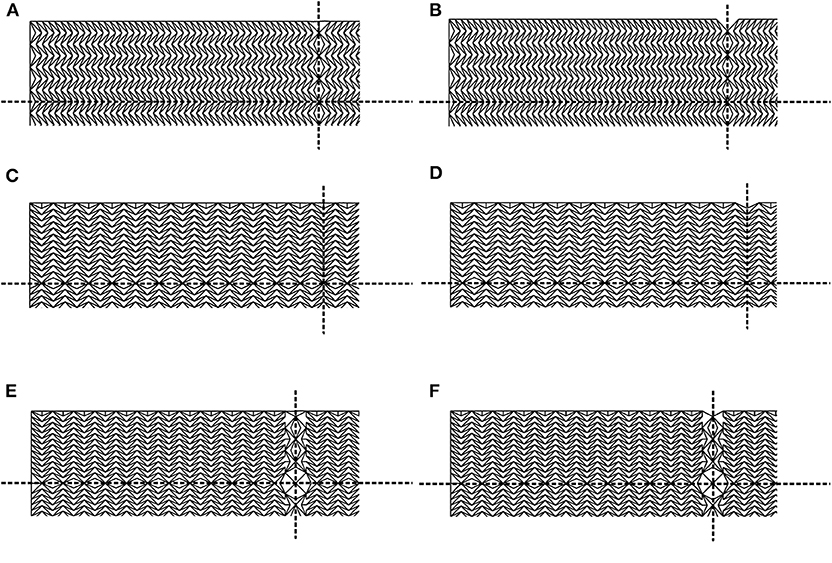
Figure 10. Lattice cores with (A,B) horizontal, (C,D) vertical, and (E,F) both vertical and horizontal interruptions along the two dashed lines of symmetry, midspan, and mid-depth, respectively, labeled as: (A) AHBFMS, (B) , (C) AVBFVS, (D) , (E) AVHI1, and (F) . (A,C,E) are with face plate elements at midspan; (B,D,F) are the respective panels with the midspan face plate element has been omitted.
In order to compare the hybrid model against those with disruptions fairly, previous panel cases have been re-run with the new inclination angles; the panel configurations for these models are presented in Figure 10. The equilibrium paths comparing two sets of three panel cases are presented in Figure 11. The relationships shown in Figure 11A show the cases with face plate elements at midspan and those in Figure 11B show the cases where those midspan elements have been omitted. In both graphs, there is a clear reduction in the axial stiffness of the panels with horizontally orientated cells within the pure compression phase, as shown by the dashed lines of AHBFMS and . However, they both are shown to possess the more desirable plateauing post-buckling behavior. In contrast, the panels with the vertically orientated cells are initially stiffer and have a greater load-carrying capacity. In general, the cases with face plate elements at midspan display very unstable post-buckling behavior with sudden losses in load capacity beyond the triggering of the initial instability. Moreover, convergence issues terminate the analyses as the stress concentrations and deformations within those regions become excessively large. The removal of these face plate elements alleviate these high stress concentrations somewhat and enable the main collapse to occur at midspan since it further reduces the stiffness of the panel in that region. In the horizontally orientated panel cases, AHBFMS and , this also leads to a drop of approximately 35% in the load-carrying capacity (see Table 2).
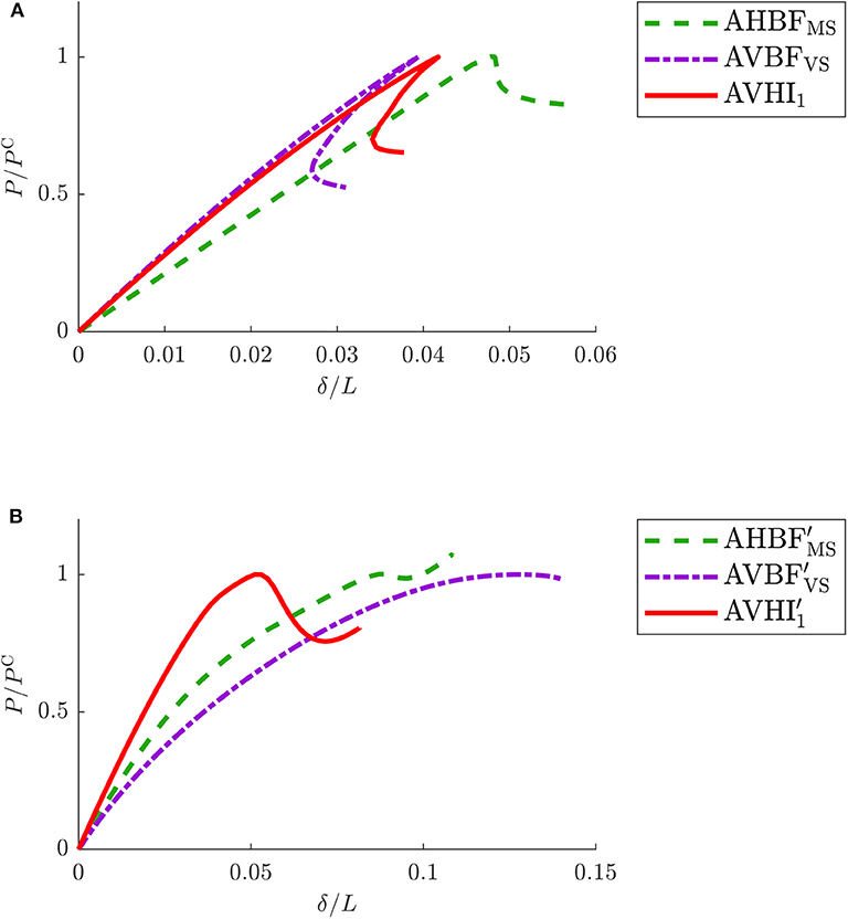
Figure 11. Normalized load P/PC vs. normalized end-shortening δ/L behavior for the three lattice core cases with disruptions where: (A) AVHI1, AHBFMS and AVBFVS are with midspan face plate elements and (B) , , and are with midspan face plate elements omitted.
Case shows the most favorable buckling behavior with a combination of the best characteristics from the other similar model cases; a higher initial stiffness with a reasonable load-carrying capacity and a minimal post-buckling stiffness. The destabilizing behavior beyond the initial instability also improves with a subsequent restabilizing characteristic that may in future by refined and extended to produce cellular buckling more formally.
A more thorough three-stage diagnosis of the equilibrium path of panel is shown in Figure 12 with corresponding contour plots depicting the axial forces and deformations at those specific points. Stage (1) shows the deformations at the ultimate load, where most of the arrowhead beams at the central disruption column begin buckling, leading to a reduction in the stiffness of the panel. In the contour plots, the lightly shaded (green, cyan, and yellow) areas show beams with low axial forces to ones which are under significant tension (shown in red). The darker colors (primarily blue) show the beams that are under compression. Stage (2) represents the restabilization point in the equilibrium diagram; most of the cells in the central disruption column have fully buckled and coalesced with the main cross-beams within the central region of the panel being under compression and upholds the structural integrity of that region. By stage (3), the central cross-beams have bent further with the compressive forces within that region being reduced alongside an outward redistribution of the compression forces within the lattice being observed. Hence, stages (2) and (3) may be considered to be analogues of points (B) and (C) on the graph showing the mechanical response of a conventional cellular core material in Figure 3. This demonstrates that a lattice material can feasibly replicate the mechanical behavior of a cellular core by introducing bespoke geometrical arrangements.
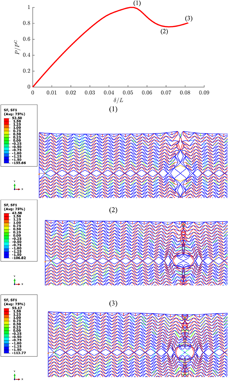
Figure 12. Normalized load P/PC vs. normalized end-shortening δ/L behavior for with axial force (“SF”) contour plots in Newtons (N) marking three distinct points on the corresponding equilibrium path.
Plans for future work include modeling three-dimensional panels with Timoshenko 3D beam elements (B32) with the aim of producing more realistic results. This is where the initial instability and subsequent densification behavior, observed in stages (2) and (3) in Figure 12 respectively, can be modeled to include contact between individual lattice elements. In particular, the inclusion of contact would affect the restiffening characteristics resulting from densification. Current results suggest that a lattice arrangement has been determined that provides a limited unstable post-buckling range and restabilization without an enormous drop in load-carrying capacity. More disruptions along the length of the panel can also be included, whereby the response could be engineered to provide a sequence of snaking-type instabilities that were discussed in sections 2 and 3.1. This would increase the energy absorption capacity while maintaining the low underlying stiffness which is desired for structural isolation. Looking further ahead, features such as inelasticity within the beam material and the inertial effects of dynamic loads on the sandwich panel and core lattice can be readily introduced within the finite element modeling framework. It is postulated that the results from the current study, which employs quasi-static loads and elastic behavior, would be valuable for understanding the phenomena underpinning the response observed in more sophisticated models.
The present study utilizes a purely numerical approach and further validation of the results through experimental work is clearly necessary. Moreover, the practicality of fabricating the proposed panels through additive manufacturing techniques is crucial. Although the scale used in this study is within the feasibility threshold of 3D printers that use SLS methods (Villette et al., 2015; Villette, 2016), it is equally important to demonstrate that the currently determined characteristics can be scaled. A limited study is therefore conducted using unit cell types A1 and A2, which had the more favorable mechanical responses found in the study presented in section 5.1, and were used later in the full panel studies. These configurations are scaled up by factors of 5, 10, and 15, i.e., by increasing the width B, the thickness t and the breadth c values by one of these scaling factors. Figure 13A shows the normalized load vs. normalized end-shortening responses of these newly-scaled unit cells. A practically perfect match is seen for both cell-types A1 and A2, which demonstrates that these unit cell models are indeed scalable. To examine whether these results are transferable to the full panel behavior, a comparison is made between the finally optimized panel with central disruptions determined in section 5.4, and a newly-scaled version that is enlarged by a scale factor of 5, such that the relative density is maintained to be 0.3. Figure 13B, shows another practically perfect match in the normalized equilibrium paths of these panels further demonstrating the scalability.
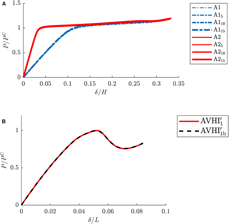
Figure 13. Normalized load vs. normalized end-shortening behavior for unit cells and sandwich panels. (A) P/PC vs. δ/H comparisons of the shallower cell types A1 and A2 with scaled variations A15, A110, A115, A25, A210, and A215 which are scaled by factors of 5, 10, and 15. (B) P/PC vs. δ/L for panel types and (a scaled variation of by a factor of 5).
6. Concluding Remarks
Sandwich panels with an increasingly sophisticated series of core lattice metamaterials under axial compression have been analyzed using elastic geometrically nonlinear finite element analysis within the commercial package ABAQUS. The principal aim was to determine core arrangements that produce mechanical responses with a combination of a high fundamental stiffness and load-carrying capacity, yet with an approximately zero underlying post-buckling stiffness, such that the sandwich panel performed well with regard to energy absorption and structural isolation applications. Lattice configurations based on auxetic arrowhead cells were studied and varied by disrupting the overall, initially uniform, distribution of cells such that the mechanical behavior exhibited the desired properties. It was found that disruptions which promoted a destabilization and subsequent restabilization in the response, similar to a conventional cellular foam core, where the cells locally buckle and then restabilize due to densification, were the most suitable.
In the immediate future, the plan is to extend this work by including more disruptions longitudinally and to model the lattice structure into the third dimension alongside the inclusion of a dynamic load with nonlinear material effects such as inelasticity. The purpose of including more disruptions would be to induce a cellular buckling-type response where a sequence of destabilization and restabilization acts to absorb energy with the behavior exhibiting a negligible underlying post-buckling stiffness. By expanding the scope of modeling the lattice to the third dimension, it should become more straightforward to include contact to simulate more realistic behavior and explicitly account for the effects of densification. In the current model, without contact, inelasticity or a dynamic load, the effects of very large deformations tend to be underestimated; the inclusion of these features would explicitly provide a region where the lattice elements squash together and promote the stiffening effect of densification, thereby promoting local deformations in less stiff parts of the lattice. Notwithstanding, the current study provides valuable new insights into the potential of engineering bespoke lattice arrangements that promote mechanically advantageous behavior in sandwich panels.
Data Availability Statement
The datasets generated for this study are available on request to the corresponding author.
Author Contributions
MW and AP conceived the research project and supervised the numerical study that was conducted by AB. MW took the lead in writing the article with close support from AB and AP.
Funding
AB was funded by the United Kingdom Engineering and Physical Sciences Research Council (EPSRC) through the Centre for Doctoral Training in Sustainable Civil Engineering.
Conflict of Interest
The authors declare that the research was conducted in the absence of any commercial or financial relationships that could be construed as a potential conflict of interest.
References
Allen, H. G. (1969). Analysis and Design of Structural Sandwich Panels. Oxford: Pergamon. doi: 10.1016/B978-0-08-012870-2.50006-7
Arena, G., Groh, R. M. J., Theunissen, R., Weaver, P. M., and Pirrera, A. (2018). Design and testing of a passively adaptive inlet. Smart Mater. Struct. 27:085019. doi: 10.1088/1361-665X/aacf79
Bai, L., Wang, F., Wadee, M. A., and Yang, J. (2017). Nonlinear mode interaction in equal-leg angle struts susceptible to cellular buckling. Proc. R. Soc. A 473:20170583. doi: 10.1098/rspa.2017.0583
Bertoldi, K., Reis, P. M., Willshaw, S., and Mullin, T. (2009). Negative Poisson's ratio behavior induced by an elastic instability. Adv. Mater. 21, 1–6. doi: 10.1002/adma.200901956
Bertoldi, K., Vitelli, V., Christensen, J., and van Henke, M. (2017). Flexible mechanical metamaterials. Nat. Rev. Mater. 2:17066. doi: 10.1038/natrevmats.2017.66
Bigoni, D., Bosi, F., Dal Corso, F., and Misseroni, D. (2014). Instability of a penetrating blade. J. Mech. Phys. Solids 64, 411–425. doi: 10.1016/j.jmps.2013.12.008
Bosi, F., Dal Corso, F., Misseroni, D., Neukirch, S., and Bigoni, D. (2016). Asymptotic self-restabilization of a continuous elastic structure. Phys. Rev. E 94:063005. doi: 10.1103/PhysRevE.94.063005
Bourell, D. L., and Beaman, J. J. (2005). “Material issues in rapid prototyping,” in Virtual Modelling and Rapid Manufacturing, eds P. J. Bártolo, et al. (Balkema: Taylor & Francis), 305–310.
Brighenti, R., Spagnoli, A., Lanfranchi, M., and Soncini, F. (2016). Nonlinear deformation behaviour of auxetic cellular materials with re-entrant lattice structure. Fatigue Fract. Eng. Mater. Struct. 39, 599–610. doi: 10.1111/ffe.12381
Budd, C. J., Hunt, G. W., and Kuske, R. (2001). Asymptotics of cellular buckling close to the Maxwell load. Proc. R. Soc. A 457, 2935–2964. doi: 10.1098/rspa.2001.0843
Burke, J., and Knobloch, E. (2007). Homoclinic snaking: structure and stability. Chaos 17:037102. doi: 10.1063/1.2746816
Champneys, A. R., Dodwell, T. J., Groh, R. M. J., Hunt, G. W., Neville, R. M., Pirrera, A., et al. (2019). Happy catastrophe: recent progress in analysis and exploitation of elastic instability. Front. Appl. Math. Stat. 5:34. doi: 10.3389/fams.2019.00034
Gibson, L. J., and Ashby, M. F. (1999). Cellular Solids: Structure and Properties, 2nd Edn. Cambridge Solid State Science Series. Cambridge: Cambridge University Press.
Grima, J. N., Attard, D., Gaff, R., and Cassar, R. N. (2009). A novel process for the manufacture of auxetic foams and for their re-conversion to conventional form. Adv. Eng. Mater. 11:5. doi: 10.1002/adem.200800388
Hu, N., and Burgue no, R. (2015). Buckling-induced smart applications: recent advances and trends. Smart Mat. Struct. 24:063001. doi: 10.1088/0964-1726/24/6/063001
Hunt, G. W., Da Silva, L. S., and Manzocchi, G. M. E. (1988). Interactive buckling in sandwich structures. Proc. R. Soc. A 417, 155–177. doi: 10.1098/rspa.1988.0055
Hunt, G. W., and Dodwell, T. J. (2019). Complexity in phase transforming pin-jointed auxetic lattices. Proc. R. Soc. A 475:20180720. doi: 10.1098/rspa.2018.0720
Hunt, G. W., Lord, G. J., and Champneys, A. R. (1999). Homoclinic and heteroclinic orbits underlying the post-buckling of axially-compressed cylindrical shells. Comput. Meth. Appl. Mech. Eng. 170, 239–251. doi: 10.1016/S0045-7825(98)00197-2
Hunt, G. W., Peletier, M. A., Champneys, A. R., Woods, P. D., Wadee, M. A., Budd, C. J., et al. (2000). Cellular buckling in long structures. Nonlinear Dyn. 21, 3–29. doi: 10.1023/A:1008398006403
Hunt, G. W., and Wadee, M. A. (1998). Localization and mode interaction in sandwich structures. Proc. R. Soc. A 454, 1197–1216. doi: 10.1098/rspa.1998.0202
Körner, C., and Liebold-Ribeiro, Y. (2015). A systematic approach to identify cellular auxetic materials. Smart Mat. Struct. 24:025013. doi: 10.1088/0964-1726/24/2/025013
Masters, I. G., and Evans, K. E. (1996). Models for the elastic deformation of honeycombs. Compos. Struct. 35, 403–422. doi: 10.1016/S0263-8223(96)00054-2
Reis, P. M. (2015). A perspective on the revival of structural (in)stability with novel opportunities for function: from buckliphobia to buckliphilia. J. Appl. Mech. Trans. ASME 82, 111001-1–111001-4. doi: 10.1115/1.4031456
Schenk, M., and Guest, S. D. (2014). On zero stiffness. Proc. IMechE Part C J. Mech. Eng. Sci. 228, 1701–1714. doi: 10.1177/0954406213511903
Shen, J., and Wadee, M. A. (2018). Length effects on interactive buckling in thin-walled rectangular hollow section struts. Thin-Walled Struct. 128, 152–170. doi: 10.1016/j.tws.2017.04.006
van der Neut, A. (1969). “The interaction of local buckling and column failure of thin-walled compression members,” in Proceedings of the 12th International Congress on Applied Mechanics (Berlin: Springer). doi: 10.1007/978-3-642-85640-2_31
Villette, C. C. (2016). Structural meso and microscale finite element based approaches for the prediction of bone architecture and fracture (Ph.D. thesis). Imperial College London, London, United Kingdom.
Villette, C. C., Zaharie, D. T., and Phillips, A. T. M. (2015). “Frangible optimised lower limb surrogate for assessing injury caused by underbelly blast,” in Proceedings of the International Research Council on Biomechanics of Injury Conference (Edinburgh).
Virgin, L. N., and Davis, R. B. (2003). Vibration isolation using buckled struts. J. Sound Vibr. 260, 965–973. doi: 10.1016/S0022-460X(02)01177-X
von Kármán, T., Sechler, E. E., and Donnell, L. H. (1932). The strength of thin plates in compression. Trans. ASME 54, 54–55.
Wadee, M. A. (2000). Effects of periodic and localized imperfections on struts on nonlinear foundations and compression sandwich panels. Int. J. Solids Struct. 37, 1191–1209. doi: 10.1016/S0020-7683(98)00280-7
Wadee, M. A., and Bai, L. (2014). Cellular buckling in I-section struts. Thin-Walled Struct. 81, 89–100. doi: 10.1016/j.tws.2013.08.009
Wadee, M. A., and Edmunds, R. (2005). Kink band propagation in layered structures. J. Mech. Phys. Solids 53, 2017–2035. doi: 10.1016/j.jmps.2005.04.005
Wadee, M. A., and Farsi, M. (2014). Cellular buckling in stiffened plates. Proc. R. Soc. A 470:20140094. doi: 10.1098/rspa.2014.0094
Wadee, M. A., and Gardner, L. (2012). Cellular buckling from mode interaction in I-beams under uniform bending. Proc. R. Soc. A 468, 245–268. doi: 10.1098/rspa.2011.0400
Wadee, M. A., and Hunt, G. W. (1998). Interactively induced localized buckling in sandwich structures with core orthotropy. J. Appl. Mech. Trans. ASME 65, 523–528. doi: 10.1115/1.2789086
Wadee, M. A., Phillips, A. T. M., and Bekele, A. (2019). “From buckliphobes to buckliphiles: recent developments in exploiting positive virtues of instability,” in Advances in Engineering Materials, Structures and Systems: Innovations, Mechanics and Applications, ed A. Zingoni (Boca Raton, FL: CRC Press), 455–461. doi: 10.1201/9780429426506-81
Wadee, M. A., Yiatros, S., and Theofanous, M. (2010). Comparative studies of localized buckling in sandwich struts with different core bending models. Int. J. Non-Linear Mech. 45, 111–120. doi: 10.1016/j.ijnonlinmec.2009.10.001
Woods, P. D., and Champneys, A. R. (1999). Heteroclinic tangles and homoclinic snaking in the unfolding of a degenerate reversible Hamiltonian Hopf bifurcation. Phys. D 129, 147–170. doi: 10.1016/S0167-2789(98)00309-1
Keywords: lattice structures, sandwich panels, auxetic materials, nonlinearity, finite element modeling, additive manufacturing, cellular buckling
Citation: Wadee MA, Phillips ATM and Bekele A (2020) Effects of Disruptive Inclusions in Sandwich Core Lattices to Enhance Energy Absorbency and Structural Isolation Performance. Front. Mater. 7:134. doi: 10.3389/fmats.2020.00134
Received: 12 December 2019; Accepted: 21 April 2020;
Published: 15 May 2020.
Edited by:
Fernando Fraternali, University of Salerno, ItalyReviewed by:
Francesco Dal Corso, University of Trento, ItalyLawrence Virgin, Duke University, United States
Copyright © 2020 Wadee, Phillips and Bekele. This is an open-access article distributed under the terms of the Creative Commons Attribution License (CC BY). The use, distribution or reproduction in other forums is permitted, provided the original author(s) and the copyright owner(s) are credited and that the original publication in this journal is cited, in accordance with accepted academic practice. No use, distribution or reproduction is permitted which does not comply with these terms.
*Correspondence: M. Ahmer Wadee, YS53YWRlZUBpbXBlcmlhbC5hYy51aw==