 Sithiprumnea Dul
 Alessandro Pegoretti
 Luca Fambri
95% of researchers rate our articles as excellent or good
Learn more about the work of our research integrity team to safeguard the quality of each article we publish.
Find out more
ORIGINAL RESEARCH article
Front. Mater. , 04 February 2020
Sec. Polymeric and Composite Materials
Volume 7 - 2020 | https://doi.org/10.3389/fmats.2020.00012
This article is part of the Research Topic Recent Advances in Intrinsically Conducting Polymers and Composites View all 12 articles
Conductive carbon nanotubes (CNT)/acrylonitrile butadiene styrene (ABS) nanocomposites parts were easily and successfully manufactured by fused filament fabrication (FFF) starting from composite filaments properly extruded at a laboratory scale. Specific specimens for strain monitoring application were properly evaluated in both short term and long term mechanical testing. In particular, samples of ABS filled with 6 wt.% of CNT were additively manufactured in two different infill patterns: HC (0°/0°) and H45 (−45°/+45°). The piezoresistivity behavior was investigated under various loading conditions such as ramp tensile tests at different rate and extension, and also creep and cyclic loading at room temperature. Experimental work revealed that the resistance changes in the conductive samples were properly detectable during stress or strain modification, as consequence of damage and/or reassembling of the percolation network. The measurement of the gauge factor in various testing conditions evidenced an initial higher sensitivity of the 3D-built parts within H45 pattern in comparison to the correspondent HC counterparts. The CNT conductive network path in the investigated samples seems to be reformed during creep and cycling experiments, showing a progressive reduction of gauge factor that seems to stabilize at about 2.5 for both HC and H45 samples after long term testing. These findings suggest that conductive CNT/ABS nanocomposites at 6 wt.% of loading can be successfully processed by FFF to produce stable strain sensors in the range −25° and +60°C, as confirmed by the constancy of resistivity in these temperatures.
Polymer composites with carbonaceous micro and nano-scale reinforcement have been extensively investigated due to their outstanding mechanical, electrical, and thermal properties. In particular, nanocomposites not only have remarkable properties that can be tailored for broad application in many fields, but their processability is also simple. Nanocomposites could help the development of light-weight structural materials and functional materials (Park and Seo, 2012; Mittal et al., 2015; Chen et al., 2018; Mohan et al., 2018). One interesting possibility offered by functional nanocomposites is to exploit their piezoelectric response for structural health monitoring (SHM) (Pegoretti, 2019). Sensing internal strain/stress can allow the detection of damage within a structural member during their lifetime (Georgousis et al., 2015; Moriche et al., 2016b; Saleh et al., 2019). This self-sensing with functional materials in fact, is a cost-effective method in comparison to other SHM methods such as acoustic emission or sonic infrared imaging.
Strain sensing with electrical conductive nanocomposites is based on the electrical resistance changes induced by deformation (piezoresistivity) and damages (loss of continuity) under loading conditions. The piezoresistivity behavior in nanocomposites is induced by the destruction of the conductive networks of nanofiller, the modification of tunneling resistance change in neighboring nanoparticles because of change of distance between them, and changes in piezoresistive of nanofillers themselves during applied deformation. Among these three factors, the first two are most likely the most influential on the electrical resistance upon mechanical deformation (Georgousis et al., 2015). The common matrices used for strain sensor materials can be thermosetting (Ku-Herrera and Avilés, 2012; Moriche et al., 2016b; Sanli et al., 2016), thermoplastics (Georgousis et al., 2015; Bautista-Quijano et al., 2016; Dawoud et al., 2018), and elastomers (Bautista-Quijano et al., 2010, 2013; Oliva-Avilés et al., 2011; Alsharari et al., 2018; Christ et al., 2019; Kim et al., 2019).
In recent years, increasing interest has focused on the producing of sensors through 3D printing technology or embedding 3D-printed components to traditional sensors. The main applicative areas are represented by electronics, force, motion, hearing, optics, etc… (Xu et al., 2017). 3D printing sensors have been achieved by several methods such as fused filament fabrication (FFF) (Alsharari et al., 2018; Dawoud et al., 2018), direct ink writing (DIW) (Muth et al., 2014), stereolithography (SLA) (Lee et al., 2015), laminated object manufacturing (LOM) (Park et al., 2012), selective laser sintering (SLS) (Ambrosi et al., 2016), photopolymer jetting (Polyjet) (Laszczak et al., 2015), and binder jetting (3DP) (Rivadeneyra et al., 2015). The frequently used conductive fillers for strain sensing applications are metal nanoparticles [e.g., silver (Lee et al., 2015), copper (Credi et al., 2016; Saleh et al., 2019), and Ti/Au (Cho et al., 2015)] and carbon-based fillers [e.g., carbon nanotubes (CNT) (Czyżewski et al., 2009; Bautista-Quijano et al., 2010; Oliva-Avilés et al., 2011; Pedrazzoli et al., 2012a; Zhao et al., 2013; Georgousis et al., 2015), carbon nanofibre (Pedrazzoli et al., 2012a), graphene (Moriche et al., 2016a,b; Alsharari et al., 2018), and carbon black (Dawoud et al., 2018; Zhao et al., 2018)]. In particular, however, only few reports are available on piezoresistive materials obtained through FFF technique, which is the dominated technique in 3D printing of polymers. Highly stretchable materials consisting of the blend of graphene-based polylactic acid (PLA) with thermoplastic polyurethane (TPU) were produced through the FFF process (Alsharari et al., 2018). The behavior of the obtained 3D-printed conductive composites was reversible until strain levels as high as 50%. Strain sensing of carbon black (CB) filled acrylonitrile butadiene styrene (ABS) nanocomposites was also investigated (Dawoud et al., 2018). The 3D-printed parts were produced with different raster angles and air gap parameters. PLA-carbon based nanocomposites derived from 3D printing have been also investigated on electrical and/or thermal conductivity (Guo et al., 2019; Ivanov et al., 2019). In order to produce strain sensor by using PLA conductive composites (Maurizi et al., 2019), the dependence of piezoresistive behavior on temperature should be properly considered. In particular taking into consideration the Tg of PLA matrix, a specific approach to compensate the temperature effect on resistivity of PLA conductive sample in the range 20–50°C has been discussed (Daniel et al., 2018; Coleman et al., 2019). The crucial effect of heating and distorsion in PLA conductive composites after voltage application has been recently detailed in dependence on the various process factors (extrusion and additive manufacturing); the authors compared the role of conductive filler (carbon black, carbon nanotubes, and nano copper wires) on resistivity in view of application for thermal sensors and piezo-resistive sensors (Watschke et al., 2019). Commercial graphene-PLA filaments with resistivity of 0.6 Ω.cm, are designed to be used for room-temperature operation, due to the low softening temperature (50°C), and for low-voltage and low-current only (lower than 12 volts and 100 mA, respectively)1. The use of low-cost conductive composite (Carbomorph) based on polycaprolactone with resistivity of 9–12 Ω.cm is also limited for piezoresistive sensors at room temperature, or at lower temperature, due to melting temperature of polymer matrix (65°C) (Leigh et al., 2012). In order to enlarge the application fields with high performance properties, especially for high temperature, a different approach was recently proposed with the processing and 3D printing up to 380°C of thermoplastic polyimide (TPI) filled with CNT; the change of resistance under cyclic bending deformation were properly studied and considered for aerospace application (Ye et al., 2019). A commercial filament Proto-Pasta PLA filled with carbon black was 3D printed as a strain sensor (Munasinghe et al., 2019). The authors determined a nearly linear relationship between the electrical resistance (up to 6.05%) and the strain; in the same time, they concluded that a long term suitability of sensor materials for creep loading and a better understanding of their viscoelastic behavior would be object of future research.
In our previous works, highly conductive ABS/CNT nanocomposites with 6 wt.% of nanofillers were successfully 3D-printed through FFF process and their extensive characterization including tensile, thermal and electrical properties was reported (Dul et al., 2018a). The composition percentage of 6 wt.% of CNT was properly selected in the tested range 2–8% wt.%, as an adequate compromise between the improvement of some properties after addition of the filler, and the correspondent reduction of composite processability, as evidenced by the critical decrease of melt flow (Dul et al., 2018b) and melt viscosity (Ecco et al., 2018). Electrical and magnetic properties of both graphene and CNT nanocomposites were studied and compared in view of EMI-SE applications (Ecco et al., 2018). Moreover their hybrid 6 wt.% nanocomposites with composition of graphene and CNT were also considered, in order to define suitable composites with relatively easy flowability for low CNT content, and adequate electrical and magnetic properties for high CNT content (Dul et al., 2020). Another recent work reported about piezoresistivity of ABS filled with 5% CNT nanocomposites through 3D printing with resistivity of about 100 Ω.cm. The authors studied and compared a balanced effect of filler content and process on the fracture properties and on the samples conductivity (Thaler et al., 2019). On the other hand, a much lower resistivity in the range of about 29 and 0.9 Ω.cm was obtained for CNT/ABS plates with composition between 2 and 8 wt.% of nanofiller, respectively (Dul et al., 2018b).
Therefore, in the actual scenario of the additive manufacturing for the fabrication of conductive and functional parts, the present work has been also devoted for a specific evaluation of various effects, such as temperature, applied strain rate and loading/unloading cycles. In particular, the strain monitoring of ABS nanocomposites at 6 wt.% of CNT prepared by FFF technique has been investigated. Two different raster angles and different testing conditions cyclic test were evaluated and compared to test the piezoresistive behavior of 3D-printed parts, not only in short term testing (i.e., temperature effect, fracture test, and applied strain rate), but also in long term testing such as creep experiments and cycling test, for the evaluation and evolution of gauge factor.
Carbon nanotube (CNT) (tradename NC7000™ multi-walled carbon nanotubes) were provided by Nanocyl S.A. Sambreville, Belgium). The technical data sheet2 reports an average length of 1.5 μm, a diameter of 9.5 nm and a surface area of 250–300 m2/g. TEM analysis is reported in literature (Dul et al., 2018b).
Acrylonitrile-butadiene-styrene (ABS) with tradename Sinkral®F322, used in this study as polymer matrix, was kindly provided by Versalis S.p.A. (Mantova, Italy). According to the producer's technical data sheet3, the polymer is characterized by a melt volume rate of 14 cm3/10 min (220°C/10 kg) and a density of 1.04 g/cm3. Before processing, ABS chips were dried under vacuum at 80°C for at least 2 h.
An selected composition (Dul et al., 2018b; Ecco et al., 2018) of 6 wt.% of CNT were first melt blended with ABS matrix through a Thermo-Haake Polylab Rheomix counter-rotating internal mixer at a temperature of 190°C and rotor speed of 90 rpm for 15 min. The resulting material was granulated in a Piovan grinder Model RN 166 and grinded pieces with average size of 2.1 ± 0.6 mm) were used to feed a Thermo Haake PTW16 intermeshing co-rotating twin screw extruder (screw diameter = 16 mm; L/D ratio = 25; nozzle die diameter 1.80 mm). The temperature profile was set in the range 180–215°C along the extruder and 220°C at the nozzle. The working parameters of extrusion were set for the production of filaments with a standard diameter of about 1.70 ± 0.05 mm.
3D-printed specimens were manufactured by feeding a Sharebot HT Next Generation desktop (Sharebot NG, Italy) prototype machine for high-temperatures with the filaments obtained as described in the previous paragraph. As schematically depicted in Figure 1, dumbbell and parallelepiped specimens were built-up along different orientations: (a) horizontal concentric (HC), and (b) horizontal 45°angle (H45). All samples were produced according to the following printing parameters: object infill 100%; nozzle diameter 0.40 mm; nozzle temperature 280°C; bed temperature 110°C, layer height 0.20 mm; infill speed 40 mm/s; raster angle of [0°/0°] and [−45°/+45°], respectively.
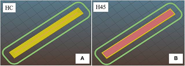
Figure 1. Schematic of 3D-printed parallelepiped: (A) horizontal concentric (HC) and (B) horizontal 45°angle (H45).
Morphology of nanocomposite filament was observed through transmission electron microscopy (TEM), using a Philips® EM 400 T (Philips, Amsterdam, The Netherlands) transmission electron microscope. Ultrathin specimen was cut into thin slices with dimensions of about 200 × 150 μm perpendicular and parallel to the flow direction by using a Leica EM UC7 ultramicrotome equipped with a diamond knife. Specimens were deposited on a copper grid mesh covered by amorphous holey carbon film.
The electrical resistance at various temperatures of 3D-printed sheets (100 × 10 × 1.4 mm) was measured by a two probes method by using ISO-TECH IDM 67 Pocket Multimeter electrometer in fridge (at −25 and +4°C) and in oven (at +60°C). HC and H45 specimens were conditioned at the selected temperature for at least 30 min before testing.
Dynamic mechanical thermal analysis (DMTA) tests were carried out under tensile mode by a TA Instruments DMA Q800 device, in the range from −100 to 150°C at a heating rate of 3°C/min applying a dynamic maximum strain of 0.05% at a frequency of 1 Hz. Storage modulus (E') and loss tangent (tanδ) as a function of the temperature were reported. 3D-printed specimen sizes were detailed in the reference (Dul et al., 2018a). One HC specimen and one H45 specimen were tested.
The monitoring of the change of electrical resistance upon the application of mechanical strain was performed on the conductive composites specimens in short term and long term experiments. The results represent the average of at least three specimens. 3D-printed sheets of 100 × 10 × 1.4 mm were tested by using an Instron®5969 electromechanical testing machine with the distance between the grips kept at 50 mm under quasi-static ramp tensile tests up to fracture, sinusoidal cyclic loading and creep tests. The ramp tests up to fracture were performed at a strain rate of 1%/min. Stress and strain at break are reported as average of three specimens (Supplementary Table S-2). For ramp strain, creep and cyclic test, the strain was measured by using the extensometer Instron® model 2620-601 with a gauge length of 12.5 mm with various strain rate (i.e., 0.3, 1, 3, and 10%/min). The results represent the average of five specimens (Supplementary Table S-3). The creep tests were performed by using the same equipment on specimens at a constant stress of 20 MPa at room temperature up to 3,600 s. A two probes setup was employed for the electrical resistance measurement at a very low voltage of 0.1 V. To ensure good electrical contact, a silver paste was applied on the surface of the conductive samples at a distance of 30 mm (see Figure 2A), and the electrical resistance was measured using a Keithley 6517A high-resistance meter as shown in Figure 2.
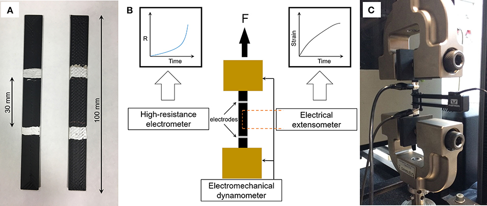
Figure 2. Experimental setup for the strain monitoring: (A) Specimens after conductive paint; (B) Schematic of experimental setup; and (C) Actual setup in tensile test.
A gauge factor (K) was calculated by using the following equation:
where R0 is the initial electrical resistance, ΔR is the variation of electrical resistance, and ε is the applied or measured strain. Gauge factor has been evaluated in both short term (quasi static) test, as average values of at least three specimens, and in long term test, such as creep and cycling measurements. See representative details of the slope of best fit line of experimental ΔR/R0 in figures; tables with data of each specimen are reported in Supplementary Materials.
Before studying the piezoelectrical behavior, morphological analysis of filaments, conductivity/resistivity measurements at various temperature and dynamical mechanical thermal analysis of 3D printed specimens were preliminarly considered.
An initial morphological analysis was performed on composite filament as extruded by twin screw extruder. Figure 3 shows TEM microanalysis of parallel surface of CNT/ABS 6 wt.%, and various carbon nanotubes appear almost randomly dispersed with some point of contact, with evidence of a connective path. Supplementary Figures are also showing the distribution and connection of CNT in both perpendicular and parallel cross-section. It should be noted that the percolation threshold of CNT in ABS has been determined at 0.42 vol.% and no electrical conductivity has been observed for CNT content lower than 2 %wt. (Dul et al., 2018b).
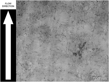
Figure 3. TEM micrograph of ABS/CNT nanocomposite filament in parallel section.
Then, in order to confirm the conductivity of 3D-printed samples, their electrical resistivity was assessed at values of 17.2 ± 1.5 and 31.2 ± 4.9 Ω.cm for HC and H45 items, respectively. As expected these values are higher than the values previously determined on compression molded plates (1.5 Ω.cm) (Dul et al., 2018b), and on the extruded filaments (4.1 Ω.cm) (Dul et al., 2018a). The increase of resistivity of extruded specimens could be attributed to the higher level of anisotropy and alignment in nanocomposite filaments, with respect to the molded plates where conversely CNT are isotropically distributed, as documented in literature (Georgousis et al., 2015; Sanli et al., 2016; Dul et al., 2018b). Moreover, the processing effect is further evidenced in 3D printed specimens and it is directly attributed to the internal structure of FFF samples. In fact, the resistance R0 of 3D-printed samples has been found to be dependent on the manufacturing infill pattern, as summarized in Table 1. In particular, significant different average resistances were observed, being 387 ± 34 Ω for HC and 671 ± 106 Ω for H45 samples, respectively. The relatively low standard deviation confirms the quality and the good homogeneity and reproducibility of the manufacturing process.
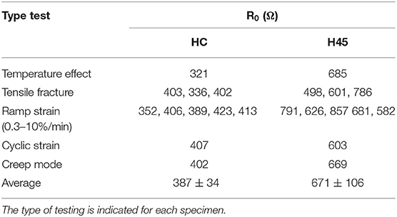
Table 1. Summary of initial resistance values (R0) at room temperature of the 3D-printed samples produced in HC and H45 configuration.
Moreover, in order to better understand the performances at various temperatures, the results of dynamic mechanical analysis on 3D-printed specimens is briefly presented and discussed. The storage modulus and loss factor values of ABS/CNT nanocomposites as a function of temperature are reported in Figure 4. Two transitions can be observed as loss tangent peaks which can be attributed to the glass transition of butadiene phase (B-phase; Tg1 = −84°C) and the glass transition of styrene–acrylonitrile phase (SAN phase; Tg2 = 125°C), respectively. This means that at room temperature, the behavior of ABS is depending on the concurrent effects of two different phases, rubbery and glassy, respectively. DMTA thermogram reveals that in the range −45/+75°C between two main transitions both storage modulus and loss factor evidence only a slight linear dependence without any other secondary transition. Consequently, taking also into account that the maximum using temperature is 83°C (determined by HDT at 1.8 MPa according to technical data sheet), precautionally the interval −25–60°C evidenced in Figure 4 has been selected for investigating electrical resistance and mechanical response.

Figure 4. DMA analysis of samples for evidencing the main viscoelastic properties of samples at a different temperature, and resistance of HC and H45 3D-printed parts in the range −20 and +60°C.
Two parallelepiped specimens built-up along different orientations, HC and H45 with resistance of 321 and 685 Ω, respectively, were selected for monitoring their electrical behavior in various isothermal conditions. The results are showed in the inset of Figure 4. No significant change in resistance was observed at 60°C; and only a very low variation of resistance of about +0.7 and +1.6% for HC and H45 samples, respectively, were evidenced at the lowest temperature. This behavior suggested that the performance of samples is stable in the selected range of temperature in direct dependence on the absence of transitions, as indicated by DMTA analysis. On the other hand conductive PLA devices evidenced significant variations of resistivity with temperature and some specific corrections have been properly suggested for analysis up to 50°C (Daniel et al., 2018). For these findings, ABS conductive nanocomposites appears more suitable for application at least up to 60°C, being the polymer matrix in the glassy state until about 90°C.
In order to investigate the effect of applied strain on the conductivity behavior, the 3D-printed nanocomposite samples (HC and H45) were tested in various mechanical loading modes; their resistivity and the initial absolute resistance were simultaneously monitored by two probe contact method. Stress-strain behavior and relative electrical resistance variation (ΔR/R0) during quasi-static tensile tests on HC and H45 samples are reported in Figure 5. Gauge factor of each test was calculated as the slope of best fit line of ΔR/R0 (coefficient of correlation R2 is reported). Due to internal alignments of deposited filaments in 3D samples, the strength of HC is slightly higher than that of H45 sample. Furthermore, tensile stress applied to 3D-printed nanocomposites causes a linear increment of the relative change of electrical resistance (ΔR/R0) until the fracture point for both samples. This behavior could be explained by the destruction of percolating paths forming the conducting network (Georgousis et al., 2015). It is important to note that H45 is more sensitive to strain change than HC due to the different infill pattern. For example, for strain of 2%, ΔR/R0 for the sample with HC is about 5.3% and for the sample with H45 is about 8.8%. The results are reported in Table 2, as average of three specimens at applied strain levels of 1, 2, and 3%. The gauge factor was found to slightly decrease with the applied strain for all the specimens (the values of each single test are reported in Supplementary Materials). Reduction of gauge factor from 2.8 to 2.4 for HC, and reduction from 4.5 to 3.2 for H45 samples were measured. Failure of the nanocomposites was detected as a pronounced increased of the electrical resistance in correspondence to the breakage of the specimen. These findings suggest potential application of this strain monitoring approach where detection of the level of damage is requested.
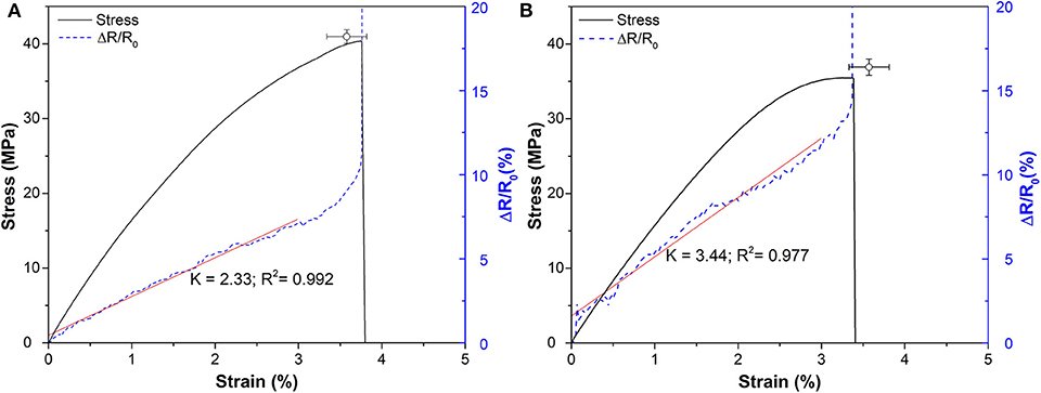
Figure 5. Representative stress/strain curve and correspondent electrical resistivity change (ΔR/R0) of 3D-printed ABS/CNT nanocomposites under applied strain up to fracture: HC (A) and H45 (B). Symbol indicates the average stress-strain at break of the three tested specimens. Gauge Factor is determined by the slope of the best fitting line.
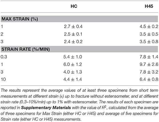
Table 2. Gauge factor (K) of ABS/CNT 3D-printed samples produced in HC and H45 configuration.
The relative change of electrical resistance (ΔR/R0) of 3D-printed samples under ramp strain measured by an electrical extensometer up to 1% at different applied strain rate (e.g., 0.3, 1, 3, and 10%/min) has been investigated and the results reported in Figure 6. No evident variations of ΔR/R0 with the strain rate have been observed. Figures 7A,B depicts representative curves of the relative resistance change of ΔR/R0 during stress/strain test performed at 0.3%/min. Gauge factor of each test was calculated as the slope of best fit line of ΔR/R0 (coefficient of correlation R2 is reported). All single data with R2 in the range 0.95–0.99 and their average are reported in Supplementary Materials. The higher the applied stress, the higher the resistance change, with an almost linear dependence for both the pattern specimens. However, it is well evident the different effect of the resistance variation of HC with respect to H45 sample, due to higher reduction of the conductivity in this latter case. It is worthwhile to note for a comparative evaluation, that the gauge factor, K, has been determined for each pattern configuration according to the formula (K = (ΔR/R0)/ε) as an average value of five specimens. The results reported in Table 2 indicate a higher piezo-resistivity for H45 3D-printed parts. In particular, the high sensitivity of the ΔR/R0 curve even at low deformation levels should be underlined. The effect of strain rate of 0.3–10%/min has no significant influence on gauge factor which remains almost constant about 5.0 and 7.0 for HC and H45, respectively. These results are consistent with those reported in different studies by Georgousis et al. (2015), Oliva-Avilés et al. (2011), Bautista-Quijano et al. (2010), and Moriche et al. (2016b).
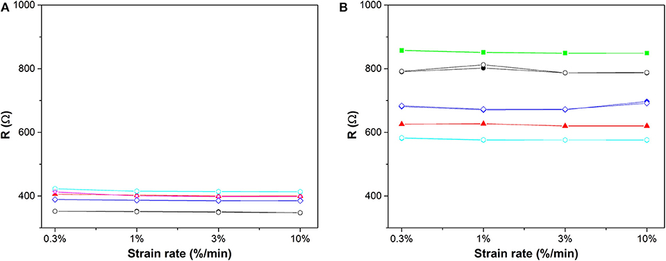
Figure 6. Resistance of 3D-printed parts before (open symbol) and after (closed symbol) applied mechanical strain at different strain rate tests: HC (A) and H45 (B). The error is lower than about 1%.
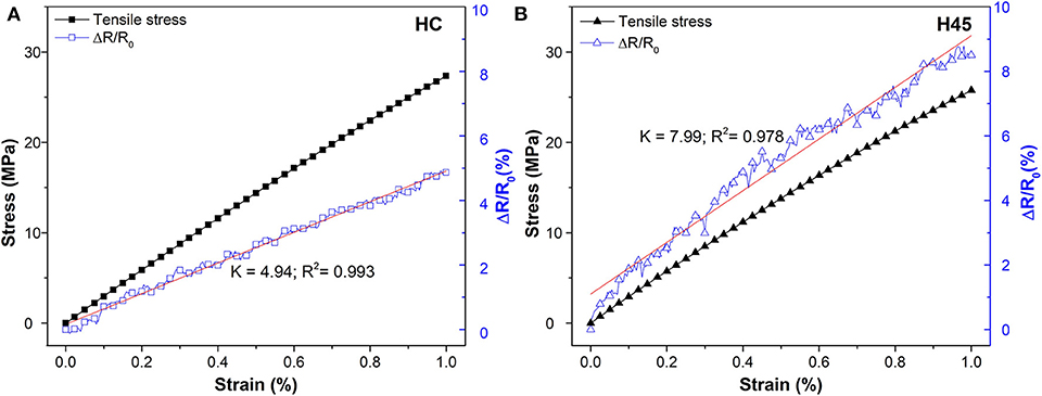
Figure 7. Representative curves of mechanical and electrical (ΔR/R0) response of 3D-printed ABS/CNT nanocomposites HC (A) and H45 (B) during tensile test at 0.3%/min. Gauge Factor is determined by the slope of the best fitting line.
Specific comparative tests have been modulated by measuring piezoresistivity of different specimens in a relatively long period with a continuous stress or cyclic loading at low level of deformation, in order to collect more information on the potentiality of strain monitoring applications of CNT/ABS nanocomposites. The performance of the samples under constant stress has been characterized during a creep test at room temperature for 3,600 s. The same stress of 20 MPa corresponding to about 50% of the stress at break has been selected for both samples. It should be noted that 20 MPa are reached at about 1.3% (Figure 5) and at about 0.7% of strain (Figure 7) at deformation rate of 1 and 0.3%/min, respectively. A creep strain of about 0.7 and 0.9% has been obtained after about 10 min of stress application for HC and H45 samples, respectively (see Supplementary Figure S-2). Moreover, it is worth noting an apparent stationary deformation for HC sample, and a slight progressive increase of creep deformation in the case H45 sample, as direct dependence on the different built-in angle (45° vs. 0°) and on the possibility of reorientation/extension of extruded filaments. And correspondingly the creep compliance, D(t), of HC sample is lower than that of H45, as shown in Figures 8A,B. In the same time the relative electrical resistance variation during creep experiments, after an initial sudden increase induced by the load application, the resistance ΔR/R0 appears to progressively decrease for both HC and H45 samples. This trend has been also previously observed in creep experiment of epoxy nanocomposites filled with carbon black (CB) and carbon nanofibers (Pedrazzoli et al., 2012b) and for epoxy/glass composites modified with a CB/CNF combination (Pedrazzoli et al., 2012a), and it could be attributed to the orientation and partial reformation of the conductive network path of the filler (Pedrazzoli et al., 2012a). Correspondingly the calculated Gauge Factor shows the tendency to decrease during creep time Figure 8C. In the initial step after 10 min, average values of 4.6 ± 0.1 and 6.5 ± 0.2 were calculated for HC and H45, respectively, quite similar to those measured in short term test at the higher strain rate (Table 2). Then an apparent stabilization was observed after 30 min (3.9 ± 0.2 for HC and 6.0 ± 0.2 for H45), and a slight further reduction in the last 15 min of creep experiments was determined with average values of 3.6 ± 0.3 for HC and 5.5 ± 0.3 for H45.
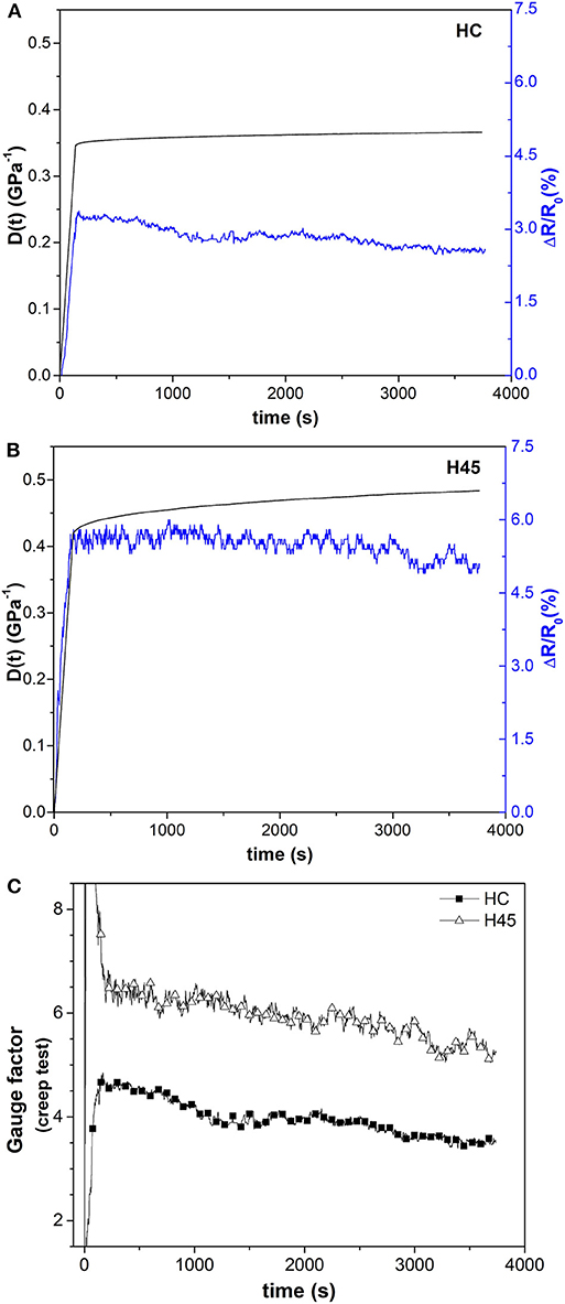
Figure 8. Creep compliance at a constant stress of 20 MPa and ΔR/R0 for different infill samples: (A) HC and (B) H45. Gauge factor evolution during creep test (C).
The resistivity decrease could be interpreted as a process of filler reorganization, similar to the case of NR and SBR, where the application of load determined the formation of new electrical path derived from alignment of CB domain (Yamaguchi et al., 2003). The same was observed for CNT in TPU (Zhang et al., 2013).
For sensor application various authors performed cycling test on conductive nanocomposites. Table 3 summarized some selected data of resistivity, gauge factor and long term testing on different polymeric matrix, such as crosslinked materials (epoxy and vinyl ester resins, silicon rubber SR) and thermoplastics polymers (PSO, TPU, PVDF, PP, PC, PLA, PI, and ABS) that have considered for applications related to the piezoelectrical behaviors. The results depend on the type of carbonaceous filler (mainly MWCNT), its content and the type of process. Long time testing with cycling has been performed following 3–10 cycles, and different effects have been observed comparing carbon black and carbon nanotube (Zhang et al., 2013; Zhao et al., 2013). A higher number of cycles was performed for glassy crosslinked system (50 cycles for graphene/epoxy) and semicrystalline matrix with rubbery phase (80 cycles for MWCNT/TPU), showing interesting information related to the variation of resistivity and gauge factor.
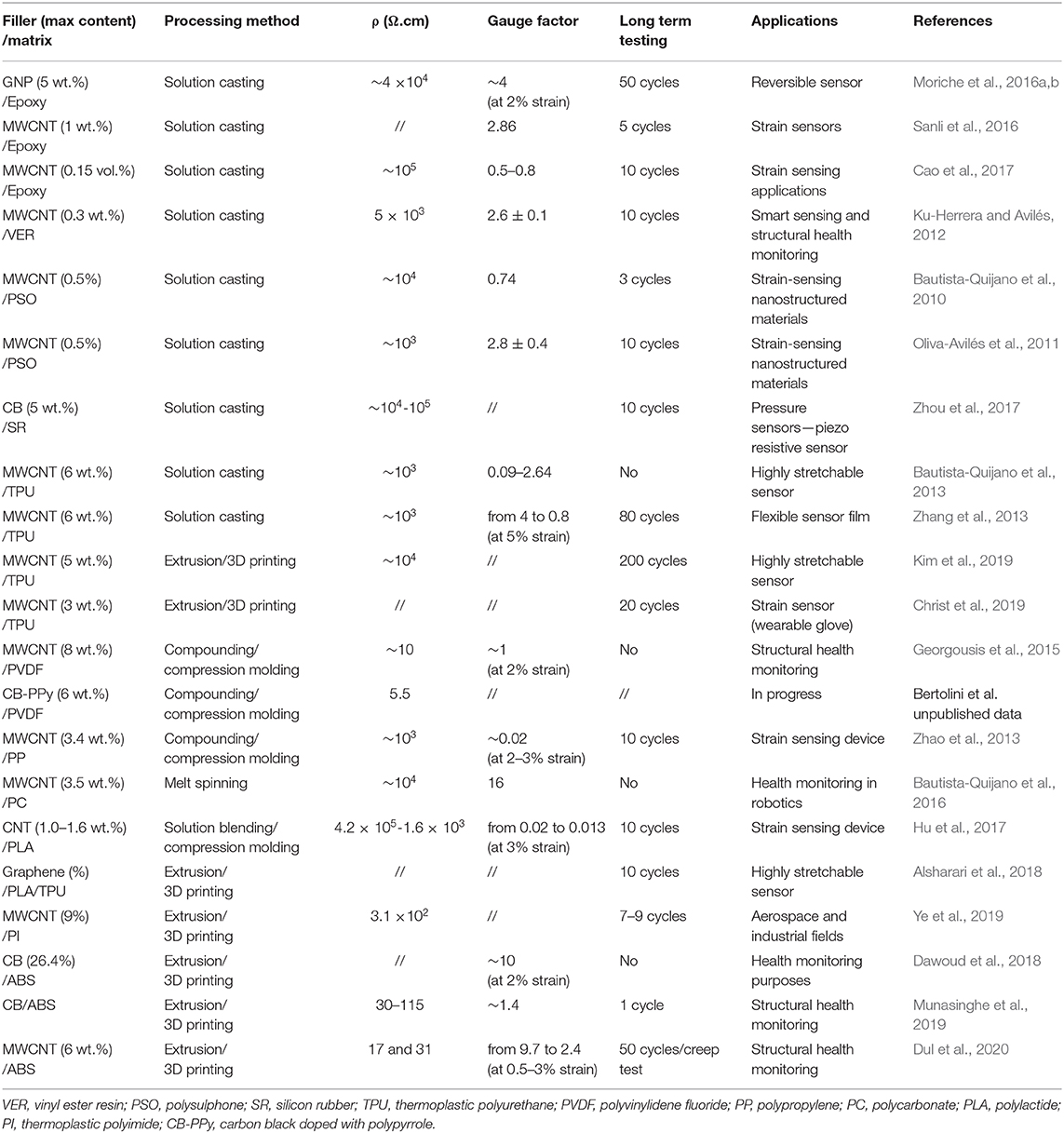
Table 3. Comparison of resistivity and piezoelectric behavior of polymer composites filled with carbon nanostructures and produced with different matrix and process.
For these reason and following the observed tendency of gauge factor of CNT/ABS to reduce during creep experiment, the authors decided to monitor the variation of electrical resistance during 50 cycles in the strain range of 0.1% < ε <0.5% for both HC and H45 samples. The results are summarized in Figures 9, 10, respectively. The resistance difference decreases with number of cycle, as derived from a dynamic mechanical effect on the nanocomposite 3D structure. It is in fact evident that piezoresistivity progressively decreases in cyclic strain for both samples. Results could be attributed to the reorganization in conductive paths, due to possible rearrangement, rotations, and reorientation, of 1D nanoparticles forming the electrical network, as reported by Bautista-Quijano et al. (2010). Different is the case observed for 2D reinforcement, such as graphene 2D nanoparticles, for which the initial electrical resistance was maintained after each cycle (Moriche et al., 2016b). An apparent stabilization of the resistance decay (electrical resistance change) has been observed in the last 10 cycles, as shown in Figures 9B, 10B for HC and H45, respectively. With the aim to evaluate the stability of strain monitoring, the effect of cyclic strain in a relatively low extent of deformation has been followed at each step of the cycle by the evaluation of a gauge factor (Ki) calculated as:
The evolution of the calculated value of gauge factor in each cycle is reported in Figure 11. It is well evident a progressive reduction of gauge factor especially for H45 samples in the first 10–15 cycles, followed by almost stationary values after 20 cycles. The average gauge factor in the first 10 cycles is about 2.8 ± 0.5 and 3.8 ± 0.6 for HC and H45, respectively; while K reaches a stable value of about 2.5 ± 0.2 for both samples after 30 cycles. These results suggest a pre-mechanical conditioning of 3D products by specific cyclic loading at controlled strain in dependence on the required applications (controlled max strain and/or max stress). The same comments were presented by various authors (Zhang et al., 2013; Zhao et al., 2013; Cao et al., 2017) with the indication of stabilization of piezoelectrical behavior during cycling loading, due to a competitive disruption and reformation of new electrical paths. In this case it is crucial the role of CNT because they can be partially realigned and they cab form some more contacts that reduce the resistivity.
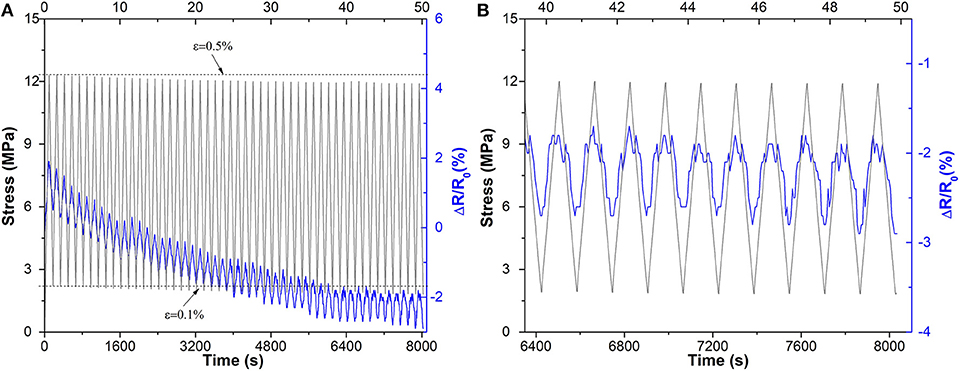
Figure 9. Piezoresistivity of the HC samples in reversible mode (A) 50 strain cycles under tensile loading and (B) detail of the last 10 cycles.
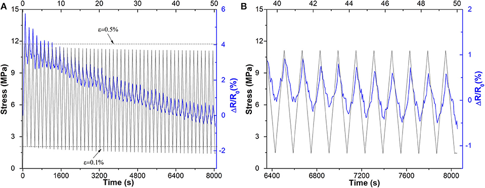
Figure 10. Piezoresistivity of the H45 samples in reversible mode (A) 50 strain cycles under tensile loading and (B) detail of the last 10 cycles.
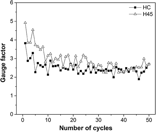
Figure 11. Gauge factor of the 6 wt.% CNT 3D-printed nanocomposite samples along a number of cycle strain of HC and H45.
Finally, it is interesting to note the effect of stress reduction during the 50 cycles of controlled strain deformation. In particular, the ratio between the maximum and the minimum stress reduced from 12.3/2.2 MPa/MPa of the first loading cycle to 11.9/1.8 MPa/MPa in the last cycle for HC sample (stress reduction of about 0.4 MPa. In the case of H45 sample, a higher stress reduction of about 0.7 MPa was observed, resulting in a max/min stress ratio of 11.8/2.1 and 11.1/1.4 MPa/MPa in the 1st and in the 50th cycle, respectively. This effect could be attributed to the viscoelastic effect of stress relaxation accompanied by thermal heating due to a mild Joule effect. During cycling deformation the progressive reduction of resistance is attributed to extension–retraction cycles, that gradually form a better conductive network, due to the partial mobility of the polymeric matrix, as previously observed for PP, PLA, TPU, and epoxy (Zhang et al., 2013; Zhao et al., 2013; Moriche et al., 2016b; Cao et al., 2017).
Representative optical pictures of HC and H45 samples before and after cyclic testing are depicted in Figure 12. After 50 cycles under tensile loading, no evidence of damage can be observed in any sample. Finally, it is worth noting a relatively low reduction of gauge factor from 3.8–4.9 to 2.5 (about 40%) for CNT/ABS, much lower than decrease gauge factor observed for MWCNT/TPU from 4 to about 0.8 after 60 cycles (Zhang et al., 2013). Hence these studied conductive nanocomposite based on MWCNT/ABS appear more suitable for strain monitoring, not only for the resistivity values, but also for relatively easy FFF processing. It should be noted however, that the maximum strain could cautiously fixed at 2% for strain monitoring device produced by FFF of CNT/ABS, whereas it is much higher in the case CNT/TPU with thermoplastic elastomer process by solution casting.

Figure 12. Optical micrographs of HC (right) and H45 (left) samples: (A) before, and (B) after 50 cycles under tensile loading.
This work shed more light on the application of conductive nanocomposites for strain monitoring, evidencing the potential of piezoresistive behavior of 3D-printed CNT/ABS composites in short term and long term testing. In particular the strain sensing capabilities of electrically conducting samples of ABS containing 6 wt.% of CNT produced by FFF with two different infill patterns (HC and H45) were evaluated. The electrical resistance of the 3D-printed specimens was observed to be dependent on the manufacturing design and to maintain almost constant values in the temperature range between −25 and 60°C. Electrical resistance changes were also monitored during short mechanical testing under different loading conditions. An initial gauge factor has been determined for each 3D printed item, and it was found directly dependent on the infill pattern. In particular, the higher sensitivity of the 3D-part within H45 pattern in comparison to HC, according to the measurement of the gauge factor. A change of the strain rate in the range of 0.3–10%/min has no significant effect on gauge factor, which is about 5.0 for HC and 7.0 for H45 part. An abrupt variation of resistance of the specimens was detected at higher deformation when damage starts to develop approaching the failure of specimen. Long time testing of conductive behavior of thermoplastic glassy polymers has been also presented for the first time, according to the authors' knowledge. Both creep experiments and cycling tests evidence the reduction of resistivity and gauge factor. The CNT conductive network path seems to be reformed during creep and fatigue test with a progressive reduction of gauge factor till an almost constant of about 2.5 for all samples. This behavior indicates a sort of rearrangement of the composite material, independently on the infill pattern, and directly related to the CNT content. In conclusion, the selection of material composition and the manufacturing of products confirmed the positive results in terms of potential applications in the field of strain monitoring.
In particular ABS conductive systems evidence a much larger interval of temperature application, with respect to commercial type composites based on PLA matrix. Moreover the composition of 6 wt.% of CNT in ABS can be relatively easy processed in quite common conditions, much more convenient with respect to high performance conductive products, such as thermoplastics polyimide, that require very high processing temperature and specific equipments for production, and in the same time guarantee a high temp application conditions.
The limits of the tested 3D printed for strain monitoring applications are the maximum using temperature (no more than 80°C) and the maximum deformation of strain 2–3%.
Each manufactured item requires to be properly calibrated and tested for the determination of its intrinsic gauge factor, and to evaluate any stabilization level depending on time and/or temperature. Some further research developments could be devoted to the long time aging up to 1–3 years, and to the evaluation of accelerated temperature aging.
The raw data supporting the conclusions of this article will be made available by the authors, without undue reservation, to any qualified researcher.
SD, AP, and LF conceived and designed the research work, analyzed the data, and wrote the paper. SD performed the experiments.
The authors declare that the research was conducted in the absence of any commercial or financial relationships that could be construed as a potential conflict of interest.
Authors wish to thank Versalis S.p.A. (Mantova, Italy) for donating ABS pellet polymer for this work. Authors are also thankful Sharebot S.r.l. (Nibionno-LC, Italy) for providing Next Generation desktop 3D-printer. Moreover, Mr. Francesco Montagnaro is warmly acknowledged for performing some of the experiments. SD is grateful to AREAS+ EU Project of Erasmus Mundus Action 2 Programme for financial support.
The Supplementary Material for this article can be found online at: https://www.frontiersin.org/articles/10.3389/fmats.2020.00012/full#supplementary-material
1. ^BlackMagic3D® PLA-Graphene conductive filaments from https://www.blackmagic3d.com/Conductive-p/grphn-pla.htm. (accessed on 14th September 2019).
2. ^Nanocyl®NC7000TM (2016) Multiwall Carbon Nanotubes Product Data from http://www.nanocyl.com/wp-content/uploads/2016/07/DM-TI-02-TDS-NC7000-V08.pdfXG (accessed on 15th April 2019).
3. ^Versalis S.p.A SINKRAL® F 322- ABS Product Data from https://www.materialdatacenter.com/ms/en/Sinkral/Versalis+S%252Ep%252EA/SINKRAL%C2%AE+F+332/c6da6726/1895 (accessed on 15th April 2019).
Alsharari, M., Chen, B., and Shu, W. (2018). 3D printing of highly stretchable and sensitive strain sensors using graphene based composites. Proceedings 2:792. doi: 10.3390/proceedings2130792
Ambrosi, A., Moo, J. G. S., and Pumera, M. (2016). Helical 3D-printed metal electrodes as custom-shaped 3D platform for electrochemical devices. Adv. Funct. Mater. 26, 698–703. doi: 10.1002/adfm.201503902
Bautista-Quijano, J. R., Avilés, F., Aguilar, J. O., and Tapia, A. (2010). Strain sensing capabilities of a piezoresistive MWCNT-polysulfone film. Sensors Actuat. A: Phys. 159, 135–140. doi: 10.1016/j.sna.2010.03.005
Bautista-Quijano, J. R., Avilés, F., and Cauich-Rodriguez, J. V. (2013). Sensing of large strain using multiwall carbon nanotube/segmented polyurethane composites. J. Appl. Polym. Sci. 130, 375–382. doi: 10.1002/app.39177
Bautista-Quijano, J. R., Pötschke, P., Brünig, H., and Heinrich, G. (2016). Strain sensing, electrical and mechanical properties of polycarbonate/multiwall carbon nanotube monofilament fibers fabricated by melt spinning. Polymer 82, 181–189. doi: 10.1016/j.polymer.2015.11.030
Cao, X., Wei, X., Li, G., Hu, C., Dai, K., Guo, J., et al. (2017). Strain sensing behaviors of epoxy nanocomposites with carbon nanotubes under cyclic deformation. Polymer 112, 1–9. doi: 10.1016/j.polymer.2017.01.068
Chen, J., Liu, B., Gao, X., and Xu, D. (2018). A review of the interfacial characteristics of polymer nanocomposites containing carbon nanotubes. RSC Adv. 8, 28048–28085. doi: 10.1039/C8RA04205E
Cho, S., Nam, T., Choi, S., Kim, M., and Kim, S. (2015). “3D printed multi-channel EEG sensors for zebrafish,” in Proceedings of 2015 IEEE Sensors (Busan), 1–3. doi: 10.1109/ICSENS.2015.7370544
Christ, J. F., Aliheidari, N., Pötschke, P., and Ameli, A. (2019). Bidirectional and stretchable piezoresistive sensors enabled by multimaterial 3D printing of carbon nanotube/thermoplastic polyurethane nanocomposites. Polymers 11:11. doi: 10.3390/polym11010011
Coleman, D., Al-Rubaiai, M., and Tan, X. (2019). “Temperature-compensation of 3D-printed polymer-based strain gauge,” in Proceedings SPIE 10968, Behavior and Mechanics of Multifunctional Materials XIII, 109680M (Denver, CO).
Credi, C., Fiorese, A., Tironi, M., Bernasconi, R., Magagnin, L., Levi, M., et al. (2016). 3D printing of cantilever-type microstructures by stereolithography of ferromagnetic photopolymers. ACS Appl. Mater. Interfaces 8, 26332–26342. doi: 10.1021/acsami.6b08880
Czyżewski, J., Burzyński, P., Gaweł, K., and Meisner, J. (2009). Rapid prototyping of electrically conductive components using 3D printing technology. J. Mater. Process. Technol. 209, 5281–5285. doi: 10.1016/j.jmatprotec.2009.03.015
Daniel, F., Patoary, N. H., Moore, A. L., Weiss, L., and Radadia, A. D. (2018). Temperature-dependent. electrical resistance of conductive polylactic acid filament for fused deposition modeling. Int. J. Adv. Manuf. Technol. 99, 1215–1224. doi: 10.1007/s00170-018-2490-z
Dawoud, M., Taha, I., and Ebeid, S. J. (2018). Strain sensing behaviour of 3D printed carbon black filled ABS. J. Manuf. Process. 35, 337–342. doi: 10.1016/j.jmapro.2018.08.012
Dul, S., Ecco, L. G., Pegoretti, A., and Fambri, L. (2020). Graphene/carbon nanotubes hybrid nanocomposites: effect of compression moulding and fused filament fabrication on properties. Polymers 12:101. doi: 10.3390/polym12010101
Dul, S., Fambri, L., and Pegoretti, A. (2018a). Filaments production and fused deposition modelling of ABS/carbon nanotubes composites. Nanomaterials 8:49. doi: 10.3390/nano8010049
Dul, S., Pegoretti, A., and Fambri, L. (2018b). Effects of the nanofillers on physical properties of acrylonitrile-butadiene-styrene nanocomposites: comparison of graphene nanoplatelets and multiwall carbon nanotubes. Nanomaterials 8:674. doi: 10.3390/nano8090674
Ecco, L., Dul, S., Schmitz, D., Barra, G., Soares, B., Fambri, L., et al. (2018). Rapid prototyping of efficient electromagnetic interference shielding polymer composites via fused deposition modeling. Appl. Sci. 9:37. doi: 10.3390/app9010037
Georgousis, G., Pandis, C., Kalamiotis, A., Georgiopoulos, P., Kyritsis, A., Kontou, E., et al. (2015). Strain sensing in polymer/carbon nanotube composites by electrical resistance measurement. Compos. Part B Eng. 68(Suppl. C), 162–169. doi: 10.1016/j.compositesb.2014.08.027
Guo, R., Ren, Z., Bi, H., Xu, M., and Cai, L. (2019). Electrical and thermal conductivity of polylactic Acid (PLA)-based biocomposites by incorporation of nano-graphite fabricated with Fused Deposition Modeling. Polymers 11:549. doi: 10.3390/polym11030549
Hu, C., Li, Z., Wang, Y., Gao, J., Dai, K., Zheng, G., et al. (2017). Comparative assessment of the strain-sensing behaviors of polylactic acid nanocomposites: reduced graphene oxide or carbon nanotubes. J. Mater. Chem. C 5:2318. doi: 10.1039/C6TC05261D
Ivanov, E., Kotsilkova, R., Xia, H., Chen, Y., Donato, R. K., Donato, K., et al. (2019). PLA/Graphene/MWCNT composites with improved electrical and thermal properties suitable for FDM 3D printing applications. Appl. Sci. 9:1209. doi: 10.3390/app9061209
Kim, M., Jung, J., Jung, S., Moon, Y. H., Kim, D.-H., and Kim, J. H. (2019). Piezoresistive behaviour of additively manufactured multi-walled carbon nanotube/thermoplastic polyurethane nanocomposites. Materials 12:2613. doi: 10.3390/ma12162613
Ku-Herrera, J. J., and Avilés, F. (2012). Cyclic tension and compression piezoresistivity of carbon nanotube/vinyl ester composites in the elastic and plastic regimes. Carbon N. Y. 50, 2592–2598. doi: 10.1016/j.carbon.2012.02.018
Laszczak, P., Jiang, L., Bader, D. L., Moser, D., and Zahedi, S. (2015). Development and validation of a 3D-printed interfacial stress sensor for prosthetic applications. Med. Eng. Phys. 37, 132–137. doi: 10.1016/j.medengphy.2014.10.002
Lee, J. S., Han, C. M., Kim, J. H., and Park, K. S. (2015). Reverse-curve-arch-shaped dry EEG electrode for increased skin–electrode contact area on hairy scalps. Electron. Lett. 51, 1643–1645. doi: 10.1049/el.2015.1873
Leigh, S. J., Bradley, R. J., Purssell, C. P., Billson, D. R., and Hutchins, D. A. (2012). A simple, low-cost conductive composite material for 3D printing of electronic sensors. PLoS ONE 7:e49365. doi: 10.1371/journal.pone.0049365
Maurizi, M., Slavič, J., Cianetti, F., Jerman, M., Valentinčič, J., Lebar, A., et al. (2019). Dynamic measurements using FDM 3D-printed embedded strain sensors. Sensors 19:2661. doi: 10.3390/s19122661
Mittal, G., Dhand, V., Rhee, K. Y., Park, S.-J., and Lee, W. R. (2015). A review on carbon nanotubes and graphene as fillers in reinforced polymer nanocomposites. J. Indus. Eng. Chem. 21, 11–25. doi: 10.1016/j.jiec.2014.03.022
Mohan, V. B., Lau, K.-T., Hui, D., and Bhattacharyya, D. (2018). Graphene-based materials and their composites: a review on production, applications and product limitations. Compos. Part B Eng. 142, 200–220. doi: 10.1016/j.compositesb.2018.01.013
Moriche, R., Sánchez, M., Jiménez-Suárez, A., Prolongo, S. G., and Ureña, A. (2016a). Strain monitoring mechanisms of sensors based on the addition of graphene nanoplatelets into an epoxy matrix. Compos. Sci. Technol. 123, 65–70. doi: 10.1016/j.compscitech.2015.12.002
Moriche, R., Sánchez, M., Prolongo, S. G., Jiménez-Suárez, A., and Ureña, A. (2016b). Reversible phenomena and failure localization in self-monitoring GNP/epoxy nanocomposites. Compos. Struct. 136(Suppl. C), 101–105. doi: 10.1016/j.compstruct.2015.10.006
Munasinghe, N., Woods, M., Milesy, L., and Paul, G. (2019). “3-D printed strain sensor for structural health monitoring,” in 2019 IEEE, 1–6. Available online at: https://opus.lib.uts.edu.au/handle/10453/136992
Muth, J. T., Vogt, D. M., Truby, R. L., Mengüç, Y., Kolesky, D. B., Wood, R. J., et al. (2014). Embedded 3D printing of strain sensors within highly stretchable elastomers. Adv. Mater. 26, 6307–6312. doi: 10.1002/adma.201400334
Oliva-Avilés, A. I., Avilés, F., and Sosa, V. (2011). Electrical and piezoresistive properties of multi-walled carbon nanotube/polymer composite films aligned by an electric field. Carbon N. Y. 49, 2989–2997. doi: 10.1016/j.carbon.2011.03.017
Park, S. J., and Seo, M. K. (2012). “Carbon fiber-reinforced polymer composites: preparation, properties, and applications,” in Polymer Composites, eds P. D. S. Thomas, P. D. J. Kuruvilla, D. S. K. Malhotra, P. K. Goda, and D. M. S. Sreekala (Weinheim: Wiley-VCH Verlag GmbH & Co. KGaA) 135–183.
Park, Y., Chen, B., and Wood, R. J. (2012). Design and fabrication of soft artificial skin using embedded microchannels and liquid conductors. IEEE Sens. J. 12, 2711–2718. doi: 10.1109/JSEN.2012.2200790
Pedrazzoli, D., Dorigato, A., and Pegoretti, A. (2012a). Monitoring the mechanical behavior under ramp and creep conditions of electrically conductive polymer composites. Compos. Part A Appl. Sci. Manuf. 43, 1285–1292. doi: 10.1016/j.compositesa.2012.03.019
Pedrazzoli, D., Dorigato, A., and Pegoretti, A. (2012b). Monitoring the mechanical behaviour of electrically conductive polymer nanocomposites under ramp and creep conditions. J. Nanosci. Nanotechnol. 12, 4093–4102. doi: 10.1166/jnn.2012.6219
Pegoretti, A. (2019). Structural Health Monitoring: Current State and Future Trends. Warrendale, PA: SAE International.
Rivadeneyra, A., Fernández-Salmerón, J., Agudo-Acemel, M., López-Villanueva, J. A., Capitan-Vallvey, L. F., and Palma, A. J. (2015). Improved manufacturing process for printed cantilevers by using water removable sacrificial substrate. Sensors Actuat. A Phys. 235, 171–181. doi: 10.1016/j.sna.2015.10.019
Saleh, M. A., Kempers, R., and Melenka, G. W. (2019) 3D printed continuous wire polymer composites strain sensors for structural health monitoring. Smart Mater Struct. 28:105041. doi: 10.1088/1361-665X/aafdef
Sanli, A., Müller, C., Kanoun, O., Elibol, C., and Wagner, M. F. X. (2016). Piezoresistive characterization of multi-walled carbon nanotube-epoxy based flexible strain sensitive films by impedance spectroscopy. Compos. Sci. Technol. 122, 18–26. doi: 10.1016/j.compscitech.2015.11.012
Thaler, D., Aliheidari, N., and Ameli, A. (2019). Mechanical, electrical, and piezoresistivity behaviors of additively manufactured acrylonitrile butadiene styrene/carbon nanotube nanocomposites. Smart Mater. Struct. 28:084004–084015. doi: 10.1088/1361-665X/ab256e
Watschke, H., Hilbig, K., and Vietor, T. (2019). Design and characterization of electrically conductive structures additively manufactured by material extrusion. Appl. Sci. 9:779. doi: 10.3390/app9040779
Xu, Y., Wu, X., Guo, X., Kong, B., Zhang, M., Qian, X., et al. (2017). The boom in 3D-printed sensor technology. Sensors 17:1166. doi: 10.3390/s17051166
Yamaguchi, K., Busfield, J. J. C., and Thomas, A. G. (2003). Electrical and mechanical behavior of filled elastomers. I. The effect of strain. J. Polym. Sci. Part B Polym. Phys. 41, 2079–2089. doi: 10.1002/polb.10571
Ye, W., Wu, W., Hu, X., Lin, G., Guo, J., Qu, H., et al. (2019). 3D printing of carbon nanotubes reinforced thermoplastic polyimide composites with controllable mechanical and electrical performance. Compos. Sci. Technol. 182:107671–107679. doi: 10.1016/j.compscitech.2019.05.028
Zhang, R., Deng, H., Valenca, R., Jin, J., Qiang, F., Bilotti, E., et al. (2013). Strain sensing behaviour of elastomeric composite films containing carbon nanotubes under cyclic loading. Compos. Sci. Technol. 74, 1–5. doi: 10.1016/j.compscitech.2012.09.016
Zhao, J., Dai, K., Liu, C., Zheng, G., Wang, B., Liu, C., et al. (2013). A comparison between strain sensing behaviors of carbon black/polypropylene and carbon nanotubes/polypropylene electrically conductive composites. Compos. Part A Appl. Sci. Manuf. 48, 129–136. doi: 10.1016/j.compositesa.2013.01.004
Zhao, S., Lou, D., Li, G., Zheng, Y., Zheng, G., Dai, K., et al. (2018). Bridging the segregated structure in conductive polypropylene composites: an effective strategy to balance the sensitivity and stability of strain sensing performances. Compos. Sci. Technol. 163, 18–25. doi: 10.1016/j.compscitech.2018.05.006
Zhou, Y., Zhou, Y., Deng, H., and Fu, Q. (2017). A novel route towards tunable piezoresistive behavior in conductive polymer composites: addition of insulating filler with different size and surface characteristics composites. Compos. Part A Appl. Sci. Manuf. 96, 99–109. doi: 10.1016/j.compositesa.2017.02.002
Keywords: strain sensor, conductive composites, carbon nanotubes, fused filament fabrication, gauge factor, 3D printing
Citation: Dul S, Pegoretti A and Fambri L (2020) Fused Filament Fabrication of Piezoresistive Carbon Nanotubes Nanocomposites for Strain Monitoring. Front. Mater. 7:12. doi: 10.3389/fmats.2020.00012
Received: 19 April 2019; Accepted: 14 January 2020;
Published: 04 February 2020.
Edited by:
Sébastien Livi, Institut National des Sciences Appliquées de Lyon (INSA Lyon), FranceReviewed by:
Jean-Marie Raquez, University of Mons, BelgiumCopyright © 2020 Dul, Pegoretti and Fambri. This is an open-access article distributed under the terms of the Creative Commons Attribution License (CC BY). The use, distribution or reproduction in other forums is permitted, provided the original author(s) and the copyright owner(s) are credited and that the original publication in this journal is cited, in accordance with accepted academic practice. No use, distribution or reproduction is permitted which does not comply with these terms.
*Correspondence: Luca Fambri, bHVjYS5mYW1icmlAdW5pdG4uaXQ=
Disclaimer: All claims expressed in this article are solely those of the authors and do not necessarily represent those of their affiliated organizations, or those of the publisher, the editors and the reviewers. Any product that may be evaluated in this article or claim that may be made by its manufacturer is not guaranteed or endorsed by the publisher.
Research integrity at Frontiers
Learn more about the work of our research integrity team to safeguard the quality of each article we publish.