 Zhixiong Yan1,2Dequan Huang1,2Xiaoping Fan1,2Fenghua Zheng1,2*Qichang Pan1,2
 Zhaoling Ma1,2Hongqiang Wang1,2Youguo Huang1,2
 Qingyu Li1,2*
- 1School of Chemical and Pharmaceutical Sciences, Guangxi Normal University, Guilin, China
- 2Guangxi Key Laboratory of Low Carbon Energy Materials, Guangxi Normal University, Guilin, China
Fluorine-doped carbon coated olivine LiFePO3.938F0.062 composite (LFPF/CF) is synthesized by a simple solid-state reaction method, and the Tween40 and polyvinylidene fluoride (-(CH2-CF2)n-, PVDF) were used as carbon source and fluorine sources, respectively. Benefiting from the Tween40 (C22H42O6(C2H4O)n) is attributed to formation a homogeneous carbon layer on the surface of LiFePO4 particles. And polyvinylidene fluoride could produces fluoride in the thermal decomposition process, which is doped into carbon and LiFePO4 to form fluoride-doped carbon layer and LiFePO3.938F0.062, respectively. In this constructed architecture, the F-doped carbon layer acts as conductive network for LFP, which can enhance the electronic conductivity of overall electrode. Furthermore, the crystal lattice of LFP was enlarged by the F doping, which facilitates the Li+ intercalation/deintercalation. On the other hand, a strong electronic coupling between F-doped carbon and LiFePO3.938F0.062 can effectively suppress the shedding of carbon layer during cycling process, which keep stabilized of the reaction interface, and thus enhance the cycling stability. As a result, LFPF/CF composite shows superior rate performance (164.8, 159.2, 148.6, 135.8, and 102.3 mAh g−1 at 0.1, 0.5, 1, 5, and 10 C), and excellent cycling stability (high capacity retention of 95.6% after 500 cycles at high rate of 5 C).
Introduction
Lithium ion batteries (LIBs) have been considered as one of the promising power sources in practical applications, for examples, electric vehicles (EVs), hybrid electric vehicles (HEVs) (Armand and Tarascon, 2008; Van Noorden, 2014; Whittingham, 2014). The energy storage mechanism of LIBs is the extraction/insertion of Li+ in the electrode materials during charge/discharge process, and all of the Li+ from cathode materials (Dunn et al., 2011). Therefore, cathode materials are very important for lithium ion battery (Zheng et al., 2015; Pan et al., 2017). Among commercial cathode materials, lithium iron phosphate (LiFePO4) has aroused great interest because of its high theoretical capacity (170 mAh g−1), high safety, stability, low cost, and environment friendly (Park et al., 2007; Huang and Goodenough, 2008; Liu et al., 2009; Wu et al., 2011; Li et al., 2015, 2018; Zheng et al., 2015). However, LiFePO4 shows poor rate performance, resulting in lower mass, and charge transport kinetics, which caused by its low electronic conductivity and Li-ion diffusivity at room temperature (Wang et al., 2005; Sun et al., 2011; Yang et al., 2012; Kuss et al., 2017).
Many strategies have been proposed to improve the rate performance, such as cationic doping and surface coating. Cationic doping is a effective method to expand lithium ion diffusion channels of cathode materials, e.g., cations include Al3+, Mg2+, Co2+, Zn2+, Al3+, and anions include F−, S2−, Cl− (Chung and Chiang, 2003; Ni et al., 2005; Hui and Zhou, 2006; Liu et al., 2006; Sun et al., 2010; Chiang et al., 2012; Gao et al., 2017; Gupta et al., 2017). On the other hand, surface coating have been confirmed is another strategy to improve rate performance which due to surface coating can improve the electronic conductivity of materials (Belharouak et al., 2005; Shin et al., 2006; Liu et al., 2008; Lu et al., 2009; Wagemaker et al., 2009; Wu et al., 2013; Lepage et al., 2014; Wang B. et al., 2016; Wang L. L. et al., 2016; Wang et al., 2019). Zheng et al. synthesized carbon coated LiFePO4 by solid-state reaction method, which shows higher capacity of 125 mAh g−1 at 5 C (Huang et al., 2013). Zhang et al. prepared Li4SiO4-coated LiFePO4 by sol-gel method and microwave heating, delivers reversible capacity of 100 mAh g−1 at 5 C (Zhang et al., 2012). Therefore, these results indicate that the cationic doping or surface coating is effective approach to improve rate performance of LiFePO4. However, the electrochemical potential of LiFePO4 cannot be completely realized only by cationic doping or surface coating. Thus, an upgrade strategy combined with cationic doping and carbon coating is used to enhance the rate performance of LiFePO4. Nevertheless, the common strategy combined with cationic doping and the carbon coating is very complicated, which must via a two or three steps including the preliminary synthesis of lithium iron phosphate and subsequent surface coating and cationic doping (Shu et al., 2014; Li et al., 2015). In addition, the carbon was only modified on the surface of LiFePO4, which shows weak interaction between LiFePO4 and the carbon layers, resulting in poor rate performance and cycling stability. Therefore, it is necessary to develop simple and effective strategies to modified LiFePO4 by the combined with surface coating and cationic doping.
In this study, fluorine-doped carbon coated LiFePO3.938F0.062 was synthesized by facile one step solid phase method. And choice carbon source and fluorine sources is very important for the electrochemical performance. The Tween40 surfactant contain hydrophobic group and hydrophilic group. Therefore, Tween40 surfactant without impurity elements could uniformly mix with materials in aqueous solution and adsorb on the particle surface to form a carbon layer during heat treatment, which can coat tightly on the surface of the cathode material. While, PVDF only contains two elements of carbon and fluorine, and the fluorine content is 59%, which can contribute to form fluorine doping successfully in the heat process. The incorporation of fluorine (F) into carbon materials could tailor their electron-donor properties, which could further enhanced electronic conductivity of carbon layer and increase bonding force between carbon layer and LiFePO4. Meanwhile, fluorine (F) doped into LiFePO4 could enlarge lithium ion diffusion channel, and thus facilitates the Li+ intercalation/deintercalation. We focus on study the effect of the F-doped carbon coating and cationic doping on electrochemical performance. In addition, the physical, structural, and electrochemical properties of the F-doped carbon coat LiFePO4−xFx composites were systematically investigated. As a result, benefiting from combined the advantages of surface coating and cationic doping, the obtained LFPF/CF exhibits high reversible capacity, excellent cycling stability, and rate performance.
Experimental
Preparation of Materials
F-doped carbon coat LiFePO3.938F0.062 composites (LFPF/CF) were prepared by one step solid phase method, using Tween40 and PVDF as carbon sources and fluorine sources, respectively. The stoichiometric amount of FePO4, Li2CO3, Tween40, and PVDF were mixed by ball milling for 2 h and using deionized water as the liquid medium (The mass ratio of Tween40 and PVDF equal to 2:0.60). The obtained mixture was dried at 80°C for 12 h and disintegrated by crusher to obtain the precursor powders. As-prepared precursors were calcined at 750°C for 10 h to obtain F-doped carbon coat LiFePO3.938F0.062 composites (LFPF/CF). The same procedure was also used to synthesize carbon modified LiFePO4 in the absence of the polyvinylidene fluoride (PVDF) and pure LiFePO4 in the absence of the Tween40 and polyvinylidene fluoride (PVDF). Pure LiFePO4, carbon coated LiFePO4, and fluorine-doped carbon coated LiFePO3.938F0.062 are denoted as LFP, LFP/C, and LFPF/CF, respectively.
Characterizations
An X-ray diffraction (XRD: Rigaku, D/max 2500v/pc, Cu Kα radiation) was used to analysis the structure of all samples. In order to observe the microstructure of the powder, the scanning electron microscopy (SEM: Philips, FEI Quanta 200 FEG) and transmission electron microscopy (TEM: JEM-2010, JEOL) were carried out. Thermo gravimetric analysis (TGA) was determined by thermal analyzer (SDTO600) in air flow with temperature rising of 5°C min−1. X-ray photoelectron spectroscopy (XPS) measurements were carried out by a Phi X-Tool XPS system to determine the valence state of an element on the surface of all samples. Raman measurement of the composite was performed using a laser Raman spectrometer (Jobin Yvon, T6400).
Electrochemical Evaluation
The electrochemical performances of all samples were evaluated using CR2032 coin cells. The active materials, acetylene black, and polyvinylidene fluoride (PVDF) at a weight ratio of 8:1:1 were mixed for 2 h in an N-methyl-2-pyrrolidene (NMP) solvent, and finally obtain the cathode slurry. The slurry were coated on aluminum foil and dried in vacuum at 120°C for 24 h. Then the CR2032-type half coin cells was assembled in a Ar-filled glovebox (Etelux LAB2000). The components of the CR2032-type half coin cells are as prepared samples as cathode, lithium metal as the counter electrode, Celgards 2200 separator and A 1:1 volumetric ratio mixture of ethylene carbonate (EC) and dimethyl carbonate (DMC) containing 1 M LiPF6 as the electrolyte. The LAND CT2001A battery testing system (Wuhan, China) was used to test electrochemical performance at voltage range of 2.3–4.3 V under different rates. The cyclic voltammetry (CV) measurements were carried out on IM6 electrochemical workstation at a scan rate of 0.1 mV s−1. Electrochemical impedance spectroscopy (EIS) of the cell was measured by using IM6 electrochemical workstation, with the 5 mV amplitude of the AC signal at the frequency range between 100 kHz and 0.01 Hz.
Results and Discussion
Scheme 1 illustrates the detailed formation process of F-doped carbon coated LiFePO3.938F0.062 composites (LFPF/CF). First, the FePO4, Li2CO3, Tween40, and PVDF were mixed through a ball mill method. In this process, Tween40 could bonded with the raw materials, and adsorbed their surface, which could form obstructer film. While, PVDF exists between FePO4 and Li2CO3. Subsequently, the obtained precursor was sintered at 750°C in Ar atmosphere, and LFPF/CF composite was obtained. Tween40 form a homogenous carbon layer on the surface of particles, and fluoride from PVDF decomposition at high temperature process is doped into carbon layer and bulk materials to form F-doped carbon coat LiFePO3.938F0.062 composite. Hence, the optimal x value, F content of F-doped carbon layer and the carbon content were chosen in the follow-up investigation (Table S5 and Figures S5, S6).
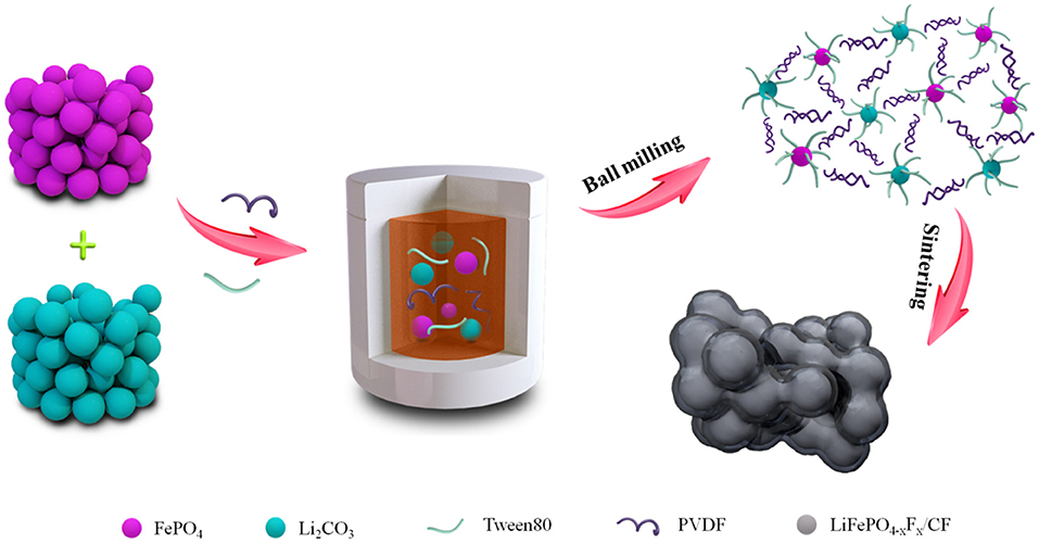
Scheme 1. Schematic illustration of the fabrication of fluorine doped carbon coated LiFePO4−xFx composite.
Figure 1A shows the XRD patterns of pure LFP, LFP/C, and LFPF/CF composite. The characteristic peaks of all samples belong to single phase of orthorhombic olivine-type structure LiFePO4 with the Pnma space group (Figure 1D) (Choi and Kumta, 2007). There are no other characteristic peaks in the LFP/C and LFPF/CF sample, suggesting that carbon content is extremely low, and have little effect on the structure. In order to analysis the XRD data of all samples (Figure 1B and Figures S1A,B), the Rietveld refinement method was implemented, and the crystallographic data were summarized in Table S1. A slight decrease of the lattice parameter a, b, and c indicated that F has been successfully doped into the crystal lattice. Concerning fluorine ion, some references suggest that it is substituted for the oxygen rather than the whole group. Meanwhile, group has very high formation energy, so it can't be replaced by fluorine (Liao et al., 2007; Pan et al., 2011; Milovic et al., 2013). The lattice parameters evolution inferred that the average bond lengths of P-O in the group decrease after F doped, which due to the ionic size of F− (1.33 Å) is smaller that of O2− (1.40 Å) and fluorine are highly electronegative (Shannon and Prewitt, 1969). Therefore, the contractions of the group enlarged the lithium ion diffusion tunnel after F doped, which lead to the lithium ions deintercalate/intercalate more easily in the tunnel (Figure 2).
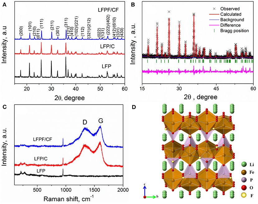
Figure 1. (A) XRD pattern of LFP, LFP/C, and LFPF/CF composite, (B) Rietveld refinement plot of LFPF/CF, (C) Raman patterns of LFP, LFP/C, and LFPF/CF composite, and (D) The crystal structure of LFPF/CF composite.
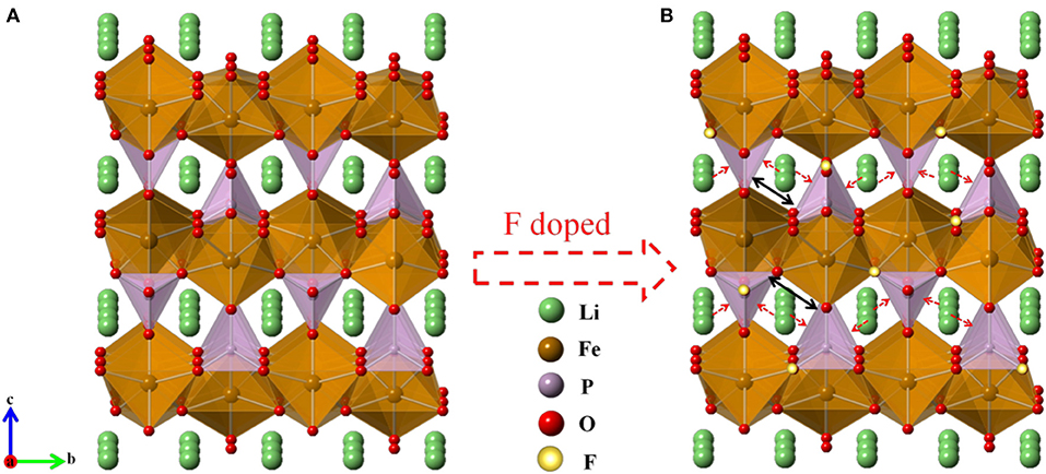
Figure 2. Refined crystal structure of each material of (A) pure LFP and (B) Fluorine-doped carbon coated olivine LiFePO3.938F0.062.
Raman spectroscopy was used to study the exist of carbon and the effect of F-doped on the structure of carbon layer. Figure 1C exhibits the Raman spectra of pure LFP, LFP/C, and LFPF/CF. All samples shows a relatively small band at about 948 cm−1, which is assigned to the symmetric PO4 stretching vibration of the LiFePO4. The bands below 400 cm−1 are assigned to vibration of Fe-O (Wu et al., 2013). In addition, two bands at 1,350 and 1,605 cm−1 for both LFP/C and LFPF/CF composite are related to the D and G bands of carbon, respectively. The D and G bands are ascribed to the sp2 graphite-like structure and the sp3 type carbon, respectively (Tian et al., 2015). Furthermore, LFPF/CF composite shows higher ID/IG (0.975) value than that of LFP/C (0.911), which are assigned to increase the defects in carbon layer after fluorine doped. Therefore, the F-doping carbon layer provides sufficient electronic pathways, and consequently enhances the kinetic process. In addition, The carbon content of LFP/C and LFPF/CF composites are analyzed by TGA, and the carbon content in the samples is about 1.83 and 2.02%, respectively (Figure S2).
In order to analyze the chemical states and compositions of pure LFP, LFP/C, and LFPF/CF, the X-ray photoelectron spectroscopy (XPS) was carried out, and the results are shown in Figure 3. The high-resolution of Fe 2p for pure LFP splits two peaks at 709.2 and 723.2 eV along with two satellite peaks at 713.6 and 727.6 eV, corresponding to Fe 2p3/2 and Fe 2p1/2, which proved that iron is oxidation state of +2 (Zhou et al., 2016). For LFP/C, there is no different in the position of the Fe 2p spectrum compare to pure LFP. While, the main peaks of Fe 2p for LFPF/CF composite shows a lower binding energy shifted compared to that of pure LFP, which due to the density of electron clouds increase around LiFePO4. As illustrated in Figure 4, Fluorine doping can make the carbon atom in the electron-rich state, and electron cloud tends to LFP, forming a strong electronic coupling between carbon layer and bulk material. The C1s high resolution XPS spectrum is de-convoluted into three peaks at 284.6, 285.4, and 287.9 eV, which belong to the C-C (sp3-C), C=O (sp2-C) and C-F bonds, respectively (Wu et al., 2018). Moreover, there are two peaks at 686.2 and 688.2 eV in the fitting of F1s high revolution XPS spectrum, which correspond to F-Li and F-C, respectively (Feng et al., 2017). Therefore, above results indicated that F was doped into the LFP lattice and carbon, respectively.
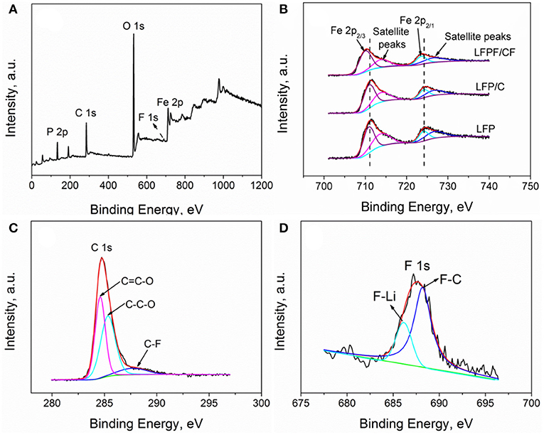
Figure 3. XPS patterns of (A) survey spectrum of LFPF/CF composites, (B) Fe 2p of LFP, LFP/C, and LFPF/CF composite, (C) C 1s, and (D) F 1s of LFPF/CF composite.
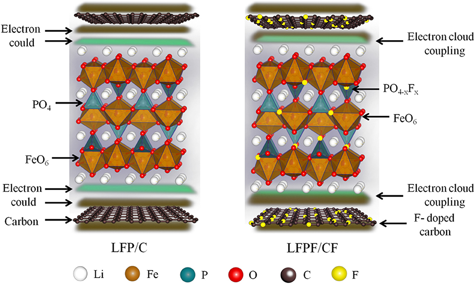
Figure 4. Illustration of the strong interaction between LiFePO4−xFx and F-doped carbon.
The effect of F-doped on the microstructure was studied by SEM. Figure 5 exhibits the SEM images of pure LFP, LFP/C, and LFPF/CF. As seen in Figure 5A, pure LFP shows agglomerated particles with a larger diameter of about 600–800 nm. However, for LFP/C and LFPF/CF, the size of particles are smaller than that of pure LFP, suggesting that carbon and F-doped carbon coated could effectively inhibit the growth of particles. Figures 5D1–D4 shows the EDX elemental mapping images of LFPF/CF. As seen Figures 5D1–D4, Fe, C, and F elements shows uniform distribution in the LFPF/CF composite, which indicated that F-doped carbon layer is homogeneously coated on the surface of the LFP particles. In addition, the tap densities of pure LFP, LFP/C, and LFPF/CF are 1.25, 1.22, and 1.20 g/cm3 (Table S2), suggesting that tap density not vary after surface modified.
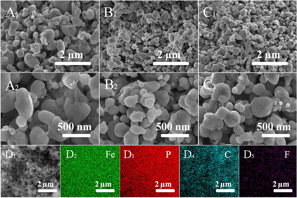
Figure 5. SEM images of pure LFP (A1,A2), LFP/C (B1,B2), LFPF/CF (C1,C2), and corresponding EDX elemental mapping images of Fe, P, C, and F (D1–D4).
Meanwhile, the microstructures of pure LFP, LFP/C, and LFPF/CF composite were further investigated by the TEM and HRTEM, and the results are shown in Figure 6. Figure 6A1 shows that the pure LFP particles with size range of 600–800 nm, which is in consistent with the SEM results. In addition, the HRTEM image shows that pure LFP exhibits a smooth surface without carbon layer (Figure 6A2). Figures 6B1,B2 shows the TEM and HRTEM images of LFP/C. The particles size of LFP/C are smaller than that of pure LFP, whereas thin carbon layer with the thickness of 2–5 nm on the surface of LFP particles were observed. Moreover, as shown in Figure 6C1, LFPF/CF shows smaller particles size than that of pure LFP, and there are F-doped carbon between LFP particles. HRTEM image of the LFP@CF (Figure 6C2) shows the F-doped carbon layer with 2–5 nm were coated on the surface of LFP particles. Meanwhile, it is observed that the d-spacing of lattice fringes for LFP and LFP/C are almost 0.272 nm, corresponding to the (102) plane of the LFP. While, LFPF/CF composite show the d-spacing of lattice fringes of 0.274 nm, which is higher than that of LFP and LFP/C. Obviously, the interlayer spacing was enlarged with fluorine doping into LiFePO4 lattice.
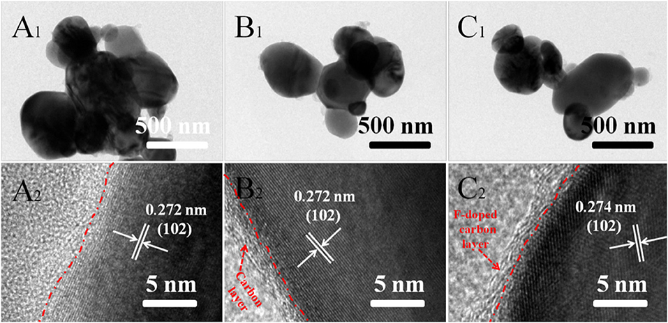
Figure 6. TEM images and HRTEM images of pure LFP (A1,A2), LFP/C (B1,B2), and LFPF/CF (C1,C2).
Figure 7A shows the initial charge/discharge curves of pure LFP, LFP/C, and LFPF/CF at 0.1 C. There are two plateaus for charge/discharge curves of pure LFP, LFP/C, and LFPF/CF, which is ascribed to Li+ intercalation/deintercalation from LiFePO4, accompanied by the oxidation/reduction of Fe2+/Fe3+ (Wang et al., 2018). Pure LFP delivers a discharge capacity of 131.8 mAh g−1 with a coulombic efficiency of 85.8%. However, the LFP/C exhibits slightly higher coulombic efficiency of 91.2%, which due to the carbon coated can increase the electronic conductivity. However, for LFPF/CF, the discharge capacity reach to 164.8 mAh g−1 with a high coulombic efficiency of 97.5%, which is higher than that of pure LFP and LFP/C. Meanwhile, LFPF/CF exhibits a lower charge voltage plateau and a higher discharge voltage plateau compared with the pure LFP and LFP/C, suggesting that LFPF/CF has lower polarization. Therefore, these results confirmed that the LFPF/CF with better ion transport ability and high electronic conductivity compare to pure LFP and LFP/C.
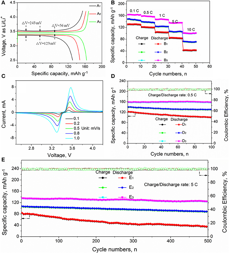
Figure 7. (A) The initial voltage profiles of (A1) pure LFP, (A2) LFP/C, and (A3) LFPF/CF composites; (B) rate performance of (B1) pure LFP, (B2) LFP/C, and (B3) LFPF/CF composites, (C) the CV curves of LFPF/CF composites at different scanning rates and cycling performance at 0.5 C rate (D) and 5 C rate (E) of (D1,E1) pure LFP, (D2,E2), LFP/C, and (D3,E3) LFPF/CF composite.
Figure 7B and Figure S3 shows the rate performance of pure LFP, LFP/C, and LFPF/CF. As seen Figure S3, the discharge capacity of LFPF/CF are 164.8, 159.2, 148.6, 135.8, and 102.3 mAh g−1 at 0.1, 0.5, 1, 2, 5, and 10 C, respectively, which shows excellent rate performance. However, the pure LFP and LFP/C delivers lower discharge capacity of 131.8, 121.7, 103.4, 83.2, and 41.6 mA h g−1 and 147.8, 139.5, 123.3, 106.8, and 72.8 mA h g−1 at 0.1, 0.5, 1, 5, and 10 C. In order to study the common effect of the F doped into LFP lattice and F-doped carbon coated the kinetic process, the cyclic voltammograms of pure LFP, LFP/C, and LFPF/CF composite at different scanning rate were performed out, and the results are provided in Figure 7C and Figure S4. The potential intervals (ΔV) are increased between the anodic peak and cathode peak of all samples with the increased scanning rate, which can be attributed to the kinetic process limitations (Huang et al., 2014). However, the LFPF/CF (Figure 7C) shows lower potential interval (ΔV) than that of pure LFP (Figure S4B) and LFP/C (Figure S4A) at different sweeping rates. Meanwhile, the redox peak current value of all samples also increases with the increase of scanning rate. The LFPF/CF exhibits higher redox peaks current than that of pure LFP and LFPF/CF composite. Above result indicated that LFP/CF has excellent kinetic process, which are attributed to the introduction of F into the lattice could enlarged interlayer spacing and F-doped carbon coated could form an electronic conductive network.
Figures 7D,E shows the cycling performance of pure LFP, LFP/C, and LFP/CF at 0.5 C and 5 C, respectively. Pure LFP can deliver a discharge capacity of 124.7 mAh g−1 with capacity retention of 82.1% after 100 cycles at 0.5 C. Nevertheless, low capacity retention of 43.5% were achieved after 500 cycles at 5C. The poor cycling stability is attributed to the kinetic process limitations, which lead to Li+ are irreversibly intercalation/deintercalation from LiFePO4 during charge/discharge process. However, LFP/C shows a capacity retentions of 92.7 and 82.3% after 100 cycle at 0.5 C and 500 cycles at 5 C, respectively, which is higher than that of pure LFP. Therefore, these results suggested that carbon coated can effective increase electronic conductivity, resulting in increased kinetic process, as well as suppress the capacity degradation to some extent during cycling process. On the other hand, the LFPF/CF can deliver outstanding cycling stability compare to that of LFP/C. The LFPF/CF deliver high specific capacity of 158.7 mAh g−1 after 100 cycles, and a high capacity retention of 98.6% is maintained. More importantly, a high capacity retention of 91.4% can be achieved even over 500 cycles at 5 C. Such excellent cycling stability can be ascribed to the introduction of F into the lattice and F-doped carbon coated enhance lithium ion diffusion and electron transport, so that more lithium ions can reversibly de/intercalate into LiFePO4 during long cycling at high rate. Meanwhile, a strong electronic coupling form the binding force between F-doped carbon layer and bulk material, which could keep the reaction interface stability of LFPF/CF.
To better explore the reasons for the improved cycling stability of LFPF/CF compare to pure LFP and LFP/C, the ICP and TEM analysis after cycling were carried out, and the results as shown in Table 1 and Figure 8. As seen Table 1, the lithium content for pure LFP in charge/discharge state are 28.53 and 72.32% after 300 cycles, suggesting lithium ion are irreversibly from the LiFePO4 lattice. Above results indicated that the irreversible deintercalation/intercalation of lithium ion increase as the increased cycles. Figures 8A1,A2 exhibits the TEM images of pure LFP after 300 and 500 cycles, and the surface and structure of pure LFP have not change, suggesting that the deterioration of cycling stability which be attributed to poor the kinetic process that cause lithium ions be irreversibly intercalated/deintercalated from LiFePO4 lattice at high rate. The lithium percentage in charge/discharge state for the LFP/C after cycling are lower/higher than that of pure LFP, suggesting that carbon coated could enhance the kinetic process. However, after 500 cycles, the lithium ion percentage after charge/discharge of LFP/C show a certain degree of increase/decrease (12.3%/85.38%). Through TEM observation, it was found that the expansion and contraction of LiFePO4 led to the shedding of carbon layer during the charge/discharge process at high rate (Figures 8B1,B2), which was caused by the different expansion coefficients of the two materials. The shedding of carbon layer directly decreases the electrical conductivity of LFP/C. By contrast, the lithium ion percentage of the LFPF/CF not vary much with the increased cycles. While we observe that the F-doped carbon layer still coated on surface of LiFePO4 after 300 and 500 cycles (Figures 8C1,C2). The difference between LFP/C and LFPF/CF is attributed to a strong electronic coupling form the binding force between F-doped carbon layer and bulk material, so as to prevent the carbon layer shedding from LiFePO4 surface, and stabilized the reaction interface of LFPF/CF composite.
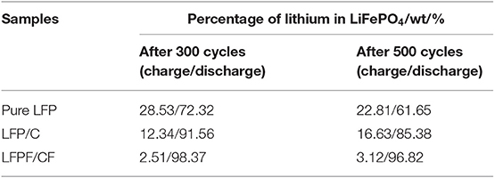
Table 1. The ICP analysis of pure LFP, LFP/C, and LFPF/CF composite after cycling, respectively (fully charged/discharge).
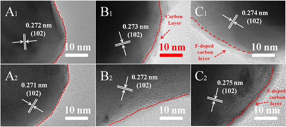
Figure 8. TEM images of all samples of pure LFP: (A1) after 300 cycles, (A2) after 500 cycles, LFP/C: (B1) after 300 cycles, (B2) after 500 cycles and LFPF/CF: (C1) after 300 cycles, (C2) after 500 cycles at 5 C rate, respectively.
Figure 9A exhibits the Nyquist plots of pure LFP, LFP/C, and LFPF/CF before and after cycling. As seen Figure 9A, the impedance spectrum is consist of an intercept at high frequency, a depressed semicircle at medium frequency and a straight line in the low frequency region, which relates to the ohmic resistance (RΩ), the charge transfer resistance (Rct) and the Warburg impedance (W), respectively. These impedance spectra were analyzed by the equivalent circuit model (Figure 9E), and corresponding parameters are shown in the Tables S3, S4. Meanwhile, the Li+ ion diffusion coefficiency () is calculated by the following equations (Li et al., 2010; Wang L. L. et al., 2016; Wang et al., 2017):
where T, R, A, F, n, C, ω is constant temperature, gas constant, surface area of cathode, Faraday constant, number of involved electrons, Li+ ions concentration, and angular frequency in the low frequency region, respectively. Meanwhile, σ is the Warburg coefficient, it is associated with Z′ against ω−1/2.
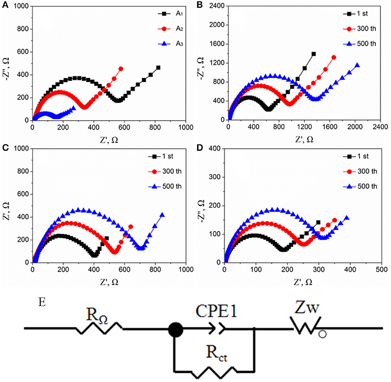
Figure 9. (A) Nyquist plots of all samples [(A1) pure LFP, (A2) LFP/C, and (A3) LFPF/CF] before cycling, (B) pure LFP, (C) LFP/C, and (D) LFPF/CF after cycling at 5 C, (E) equivalent circuit models.
The LFPF/CF composite shows Rct value of 178.6 Omega, which is lower than that of pure LFP (558.8 Ω) and LFP/C (339.2 Ω) before cycling. In addition, the Li+ diffusion coefficiency of LFPF/CF composite is 2.72 × 10⁻¹² cm2 s−1, which is higher that of pure LFP (0.87 × 10⁻¹² cm2 s−1) and LFP/C (1.43 × 10⁻¹² cm2 s−1). The results suggest that the introduction of F-doped carbon coated could greatly improve the charge and Li+ ion diffusion transport coefficiency.
Figures 9B–D show the Nyquist plots of pure LFP, LFP/C and LFPF/CF at 5 C after different cycles, respectively. For pure LFP, when the number of cycles goes from 1st to 500th, the Rct values increase from 629.8 Ω and 1372.9 Ω, and the value decreased from 0.77 × 10⁻¹² cm2 s−1 to 0.35 × 10⁻¹² cm2 s−1. The LFP/C show the increased Rct values and the decreased value after 300 and 500 cycles, which are lower than that of pure LFP. While, for LFPF/CF, the Rct values is 254.7 Ω after 300 cycles, and increased to 314.8 Ω after 500 cycles which are lower than those of pure LFP and LFPF/CF composite. Meanwhile, the value of LFPF/CF composite not vary much as the increased cycle numbers. This case clearly shows that the F-doped carbon coated can significantly keep the stability of resistance and Li+ diffusion coefficient during cycling, which is attributed to a strong electronic coupling form the binding force between F-doped carbon layer and bulk material to stabilize the reaction interface.
Conclusions
In summary, the F-doped carbon coated LiFePO3.938F0.062 composite (LFPF/CF) were synthesized by a simple solid-state reaction method. The surface of LiFePO4 particles is uniformly coated by F-doped carbon layer, and a strong electronic coupling was formed between LFP and F-doped carbon layers, which resulting in enhanced electronic conductivity and reaction interfacial stability. In addition, minor F fluorine doped into the LiFePO4 lattice, which can enlarge the lithium ion diffusion channel. As a result, the LFPF/CF shows excellent rate capability (164.8, 159.2, 148.6, 135.8, and 102.3 mAh g−1 at 0.1, 0.5, 1, 2, 5, and 10 C, respectively) and high cycling stability (high capacity retention reach 91.4% after 500 cycles at 5 C). Therefore, we believe that as-prepared F-doped carbon coated LFPF/CF composite could be one of an advanced cathode materials for Li-ion battery technology.
Data Availability Statement
The raw data supporting the conclusions of this article will be made available by the authors, without undue reservation, to any qualified researcher.
Author Contributions
ZY conducted the experiments. QL is the supervisor of this research work. ZY and FZ helped writing. ZY, DH, XF, FZ, QP, and ZM performed the characterization and data analysis. All authors involved the analysis of experimental data and manuscript preparation.
Funding
This research was supported by National Natural Science Foundation of China (51864007), Guangxi Key Research and Development Program of Science and Technology (GUIKE AB17195065 and AB17129011), and Guangxi Technology Base and Talent Subject (GUIKE AD18126001).
Conflict of Interest
The authors declare that the research was conducted in the absence of any commercial or financial relationships that could be construed as a potential conflict of interest.
Supplementary Material
The Supplementary Material for this article can be found online at: https://www.frontiersin.org/articles/10.3389/fmats.2019.00341/full#supplementary-material
References
Armand, M., and Tarascon, J. M. (2008). Building better batteries. Nature 451, 652–657. doi: 10.1038/451652a
Belharouak, I., Johnson, C., and Amine, K. (2005). Synthesis and electrochemical analysis of vapor-deposited carbon-coated LiFePO4. Electrochem. Commun. 7, 983–988. doi: 10.1016/j.elecom.2005.06.019
Chiang, C. Y., Su, H. C., Wu, P. J., Liu, H. J., Hu, C. W., Sharma, N., et al. (2012). Vanadium substitution of LiFePO4 cathode materials to enhance the capacity of LiFePO4-based lithium-ion batteries. J. Phys. Chem. C 116, 24424–24429. doi: 10.1021/jp307047w
Choi, D. W., and Kumta, P. N. (2007). Surfactant based sol-gel approach to nanostructured LiFePO4 for high rate Li-ion batteries. J. Power Sources 29, 1064–1069. doi: 10.1016/j.jpowsour.2006.09.082
Chung, S. Y., and Chiang, Y. M. (2003). Microscale measurements of the electrical conductivity of doped LiFePO4. Electrochem. Solid-State Lett. 6, A278–A281. doi: 10.1149/1.1621289
Dunn, B., Kamath, H., and Tarascon, J. (2011). Electrical energy storage for the grid: a battery of choices. Science 334, 928–935. doi: 10.1126/science.1212741
Feng, T., Jiang, W., Zong, Z., and Wu, M. (2017). Investigation of the electrochemical performance of polyvinylidene fluoride-derived LiFePO4/C composite nanospheres. J. Mater. Sci. 53, 1279–1285. doi: 10.1007/s10853-017-1585-5
Gao, L., Xu, Z., Zhang, S., Xu, J., and Tang, K. (2017). Enhanced electrochemical properties of LiFePO4 cathode materials by Co and Zr multi-doping. Solid State Ionics 305, 52–56. doi: 10.1016/j.ssi.2017.04.021
Gupta, R., Saha, S., Tomar, M., Sachdev, V. K., and Gupta, V. (2017). Effect of manganese doping on conduction in olivine LiFePO4. J. Mater. Sci. Mater. Electron. 28, 5192–5199. doi: 10.1007/s10854-016-6175-9
Huang, Y. G., Zheng, F. H., Zhang, X. H., Li, Q. Y., and Wang, H. Q. (2014). Effect of carbon coating on cycle performance of LiFePO4/C composite cathodes using Tween80 as carbon source. Electrochimica Acta 130, 740–747. doi: 10.1016/j.electacta.2014.03.091
Huang, Y. G., Zheng, F. H., Zhang, X. H., Li, Y. H., Yin, J. C., and Li, Q. Y. (2013). Tween40 surfactant effect on the formation of nano-sized LiFePO4/C powder via a solid state reaction and their cathode properties. Solid State Ionics 249, 158–164. doi: 10.1016/j.ssi.2013.08.015
Huang, Y. H., and Goodenough, J. B. (2008). High-rate LiFePO4 lithium rechargeable battery promoted by electrochemically active polymers. Chem. Mat. 20, 7237–7241. doi: 10.1021/cm8012304
Hui, X., and Zhou, Z. (2006). Physical and electrochemical properties of mix-doped lithium iron phosphate as cathode material for lithium ion battery. Electrochim. Acta 51, 2063–2067. doi: 10.1016/j.electacta.2005.07.014
Kuss, C., Trinh, N. D., Andjelic, S., Saulnier, M., Dufresne, E. M., Liang, G. X., et al. (2017). Structural transformation of LiFePO4 during ultrafast delithiation. J. Phys. Chem. Lett. 24, 6160–6164. doi: 10.1021/acs.jpclett.7b02569
Lepage, D., Sobh, F., Kuss, C., Liang, G., and Schougaard, S. B. (2014). Delithiation kinetics study of carbon coated and carbon free LiFePO4. J. Power Sources 256, 61–65. doi: 10.1016/j.jpowsour.2013.12.054
Li, Q. Y., Zheng, F. H., Huang, Y. G., Zhang, X. H., Wu, Q., Fu, D. J., et al. (2015). Surfactants assisted synthesis of nano-LiFePO4/C composite as cathode materials for lithium-ion batteries. J. Mater. Chem. A 3, 2025–2035. doi: 10.1039/C4TA03293D
Li, Z., Du, F., and Bie, X. (2010). Electrochemical kinetics of the Li[Li0.23Co0.3Mn0.47]O2 cathode material studied by GITT and EIS. J. Phys. Chem. C 114, 22751–22757. doi: 10.1021/jp1088788
Li, Z. J., Yang, J. X., Li, C. J., Wang, S. C., Zhang, L., Zhu, K. J., et al. (2018). Orientation-dependent lithium miscibility gap in LiFePO4. Chem. Mater. 3, 874–878. doi: 10.1021/acs.chemmater.7b04463
Liao, X. Z., He, Y. S., Ma, Z. F., Zhang, X. M., and Wang, L. (2007). Effects of fluorine-substitution on the electrochemical behavior of LiFePO4/C cathode materials. J. Power Sources 174, 720–725. doi: 10.1016/j.jpowsour.2007.06.146
Liu, H., Cao, Q., Fu, L. J., Li, C., Wu, Y. P., and Wu, H. Q. (2006). Doping effects of zinc on LiFePO4 cathode material for lithium ion batteries. Electrochem. Commun. 8, 1553–1557. doi: 10.1016/j.elecom.2006.07.014
Liu, H., Wang, G. X., Wexler, D., Wang, J. Z., and Liu, H. K. (2008). Electrochemical performance of LiFePO4 cathode material coated with ZrO2 nanolayer, Electrochem. Commun. 10, 165–169. doi: 10.1016/j.elecom.2007.11.016
Liu, J., Wang, J., Yan, X., Zhang, X., Yang, G., Jalbout, A. F., et al. (2009). Long-term cyclability of LiFePO4/carbon composite cathode material for lithium-ion battery applications. Electrochim. Acta 54, 5656–5659. doi: 10.1016/j.electacta.2009.05.003
Lu, C. Z., Kuo, G. T., Fey, T. K., and Kao, H. M. (2009). Study of LiFePO4 cathode materials coated with high surface area carbon. J. Power Sources 189, 155–162. doi: 10.1016/j.jpowsour.2008.10.015
Milovic, M., Jugovic, D., Cvjeticanin, N., Uskokovic, D., Milosevic, A. S., Popovic, Z. S., et al. (2013). Crystal structure analysis and first principle investigation of F doping in LiFePO4. J. Power Sources 241, 70–79. doi: 10.1016/j.jpowsour.2013.04.109
Ni, J. F., Zhou, H. H., Chen, J. T., and Zhang, X. X. (2005). LiFePO4 doped with ions prepared by co-precipitation method. Mater. Lett. 59, 2361–2365. doi: 10.1016/j.matlet.2005.02.080
Pan, M., Lin, X., and Zhou, Z. (2011). Electrochemical performance of LiFePO4/C doped with F synthesized by carbothermal reduction method using NH4F as dopant. J. Solid State Electrochem. 16, 1615–1621. doi: 10.1007/s10008-011-1564-8
Pan, Q. C., Zheng, F. H., Ou, X., Yang, C. H., Xiong, X. H., and Liu, M. L. (2017). MoS2 encapsulated SnO2-SnS/C nanosheets as a high performance anode material for lithium ion batteries. Chem. Eng. J. 316, 393–400. doi: 10.1016/j.cej.2017.01.111
Park, K. S., Schougaard, S. B., and Goodenough, J. B. (2007). Conducting-polymer/iron-redox-couple composite cathodes for lithium secondary batteries. Adv. Mater. 19, 848–851. doi: 10.1002/adma.200600369
Shannon, R. D., and Prewitt, C. T. (1969). Effective ionic radii in oxides and fluorides. Acta Crystallogr. B 25, 925–946. doi: 10.1107/S0567740869003220
Shin, H. C., Cho, W. I., and Ho, J. (2006). Electrochemical properties of carbon-coated LiFePO4 cathode using graphite, carbon black, and acetylene black. Electrochim. Acta 52, 1472–1476. doi: 10.1016/j.electacta.2006.01.078
Shu, H. B., Chen, M. F., Fu, Y. Q., Yang, X. K., Yi, X., Bai, Y. S., et al. (2014). Improvement of electrochemical performance for spherical LiFePO4 via hybrid coated with electron conductive carbon and fast Li ion conductive La0.56Li0.33TiO3. J. Power Sources 252, 73–78. doi: 10.1016/j.jpowsour.2013.11.036
Sun, C., Rajasekhara, S., Goodenough, J. B., and Zhou, F. (2011). Monodisperse porous LiFePO4 microspheres for a high power Li-ion battery cathode. J. Am. Chem. Soc.133, 2132–2135. doi: 10.1021/ja1110464
Sun, C. S., Zhang, Y., Zhang, X. J., and Zhou, Z. (2010). Structural and electrochemical properties of Cl-doped LiFePO4/C. J. Power Sources 195, 3680–3683. doi: 10.1016/j.jpowsour.2009.12.074
Tian, R., Liu, H., Jiang, Y., Chen, J., Tan, X., Liu, G., et al. (2015). Drastically enhanced high-rate performance of carbon-coated LiFePO4 nanorods using a green chemical vapor deposition (CVD) method for lithium ion battery: a selective carbon coating process. ACS Appl. Mater. Interfaces 7, 11377–11386. doi: 10.1021/acsami.5b01891
Wagemaker, M., Mulder, F. M., and Van der Ven, A. (2009). The role of surface and interface energy on phase stability of nanosized insertion compounds. Adv. Mater. 21, 2703–2709. doi: 10.1002/adma.200803038
Wang, B., Liu, T., Liu, A., Liu, G., Wang, L., Gao, T. T., et al. (2016). A hierarchical porous C@LiFePO4/carbon nanotubes microsphere composite for high-rate lithium-ion batteries: combined experimental and theoretical study. Adv. Energy Mater. 6:1600426. doi: 10.1002/aenm.201600426
Wang, B., Ruan, T., Chen, Y., Jin, F., Peng, L., Zhou, Y., et al. (2019). Graphene-based composites for electrochemical energy storage. Energy Storage Mater. 24, 22–51. doi: 10.1016/j.ensm.2019.08.004
Wang, D. Y., Wu, X. D., Wang, Z. X., and Chen, L. Q. (2005). Cracking causing cyclic instability of LiFePO4 cathode material. J. Power Sources. 140, 125–128. doi: 10.1016/j.jpowsour.2004.06.059
Wang, H. Q., Pan, Q. C., Wu, Q., Zhang, X. H., Huang, Y. G., Li, Q. Y., et al. (2017). Ultrasmall MoS2 embedded in carbon nanosheets coated Sn/SnOx as anode material for high-rate and long life Li-ion batteries. J. Mater. Chem. A 5, 4576–4582. doi: 10.1039/C6TA10932B
Wang, L. L., Hu, Z. Y., Zhao, K. N., Luo, Y. Z., Wei, Q. L., Tang, C. J., et al. (2016). Hollow spherical LiNi0.5Mn1.5O4 built from polyhedra with high-rate performance via carbon nanotube modification. Sci. China Mater. 59, 95–103. doi: 10.1007/s40843-016-0120-3
Wang, X., Feng, Z., Huang, J., Deng, W., Li, X., Zhang, H., et al. (2018). Graphene-decorated carbon-coated LiFePO4 nanospheres as a high-performance cathode material for lithium-ion batteries. Carbon 127, 149–157. doi: 10.1016/j.carbon.2017.10.101
Whittingham, M. S. (2014). Ultimate limits to intercalation reactions for lithium batteries. Chem. Rev. 114, 11414–11443. doi: 10.1021/cr5003003
Wu, J., Dathar, G. K., Sun, C., Theivanayagam, M. G., Applestone, D., Dylla, A. G., et al. (2013). In situ Raman spectroscopy of LiFePO4: size and morphology dependence during charge and self-discharge. Nanotechnology 24:424009. doi: 10.1088/0957-4484/24/42/424009
Wu, Y. M., Wen, Z. H., and Li, J. H. (2011). Hierarchical carbon-coated LiFePO4 nanoplate microspheres with high electrochemical performance for Li-ion batteries. Adv. Mater. 23, 1126–1129. doi: 10.1002/adma.201003713
Wu, Z., Li, P., Qin, Q., Li, Z., and Liu, X. (2018). N-doped graphene combined with alloys (NiCo,CoFe) and their oxides as multifunctional electrocatalysts for oxygen and hydrogen electrode reactions. Carbon 139, 35–44. doi: 10.1016/j.carbon.2018.06.028
Yang, K., Deng, F. H., and Suo, J. S. (2012). Synthesis and characterization of LiFePO4 and LiFePO4/C cathode material from lithium carboxylic acid and Fe3+. J. Power Sources 201, 274–279. doi: 10.1016/j.jpowsour.2011.11.019
Zhang, Q., Jiang, W. W., Zhou, Z. F., Wang, S. M., Guo, X. S., Zhao, S., et al. (2012). Enhanced electrochemical performance of Li4SiO4-coated LiFePO4 prepared by sol-gel method and microwave heating. Solid State Ionics 218, 31–34. doi: 10.1016/j.ssi.2012.05.006
Zheng, F. H., Yang, C. H., Xiong, X. H., Xiong, J. W., Hu, R. Z., Chen, Y., et al. (2015). Nanoscale surface modification of lithium-rich layered-oxide composite cathodes for suppressing voltage fade. Angew. Chem. Int. Ed. 54, 13058–13062. doi: 10.1002/anie.201506408
Zhou, Y. K., Lu, J. M., Deng, C. J., Zhu, H. X., Chen, G. Z., Zhang, S. W., et al. (2016). Nitrogen-doped graphene guided formation of monodisperse microspheres of LiFePO4 nanoplates as the positive electrode material of lithium-ion batteries. J. Mater. Chem. A 4, 12065–12072. doi: 10.1039/C6TA03440C
Keywords: lithium ion batteries, cathode materials, LiFePO3.938F0.062, fluorine-doped carbon, electrochemical performance
Citation: Yan Z, Huang D, Fan X, Zheng F, Pan Q, Ma Z, Wang H, Huang Y and Li Q (2020) Fluorine-Doped Carbon Coated LiFePO3.938F0.062 Composites as Cathode Materials for High-Performance Lithium-Ion Batteries. Front. Mater. 6:341. doi: 10.3389/fmats.2019.00341
Received: 30 August 2019; Accepted: 17 December 2019;
Published: 24 January 2020.
Edited by:
Feixiang Wu, Central South University, ChinaReviewed by:
Dianlong Wang, Harbin Institute of Technology, ChinaJin Tao Zhang, Nanyang Technological University, Singapore
Wang Ding, Kunming University of Science and Technology, China
Jia Feng Zhang, Central South University, China
Copyright © 2020 Yan, Huang, Fan, Zheng, Pan, Ma, Wang, Huang and Li. This is an open-access article distributed under the terms of the Creative Commons Attribution License (CC BY). The use, distribution or reproduction in other forums is permitted, provided the original author(s) and the copyright owner(s) are credited and that the original publication in this journal is cited, in accordance with accepted academic practice. No use, distribution or reproduction is permitted which does not comply with these terms.
*Correspondence: Fenghua Zheng, emhlbmdmaDg3MDYyN0AxNjMuY29t; Qingyu Li, bGlxaW5neXU2MkAxMjYuY29t