 Zhaochun Li
 Yao Gong
 Sihao Li
94% of researchers rate our articles as excellent or good
Learn more about the work of our research integrity team to safeguard the quality of each article we publish.
Find out more
ORIGINAL RESEARCH article
Front. Mater., 05 December 2019
Sec. Smart Materials
Volume 6 - 2019 | https://doi.org/10.3389/fmats.2019.00299
This article is part of the Research TopicHysteresis Characterization and Control of Electrorheological and Magnetorheological MaterialsView all 14 articles
The hysteresis non-linearity of a magnetorheological (MR) fluid damper is one of the main reasons to restrict it to be widely used in shock buffering fields. This research aims to reduce or eliminate the effect of the magnetic hysteresis of the MR damper. A magnetic hysteresis compensation control method is proposed and verified in this paper. Jiles-Atherton (J-A) model is employed to descript the hysteresis non-linearity between the adjustable damping force and the actual magnetic induction intensity in the effective damping channel of the MR fluid damper. The simulation of the magnetic compensation control system is performed to evaluate the effectiveness of the proposed method and the employed model. In order to obtain the actual magnetic induction intensity, a MR fluid damper embedded in a Hall sensor is designed and manufactured. The experimental study is carried out to verify the proposed PID control of hysteresis compensation method. Both the simulation results and the experimental results show the MR fluid damper employed proposed hysteresis compensation method with PID control can almost completely eliminate the effect of hysteresis under both low frequency and high frequency input. The experimental results indicate the hysteresis control system of MR fluid damper is of good dynamic performance which make it suitable for the shock buffering system. At last, a simulation model of the MR-damper-based impact buffer system with hysteresis compensation control is established to verify the buffer effect of the system. The output damping force of the MR impact buffer system indicates the buffer performance has been improved by employing the magnetic hysteresis compensation control method.
Magnetorheological (MR) damper is a new semi-active control device with magnetorheological fluid as working medium. It changes the shear yield stress of magnetorheological fluid by changing the current applied to the inner coil, thus changing its output damping force (Carlson, 2002). Magnetorheological damper has the advantages of simple structure, large damping force, wide adjustable range, low energy consumption, fast response speed, and wide dynamic range. Extensive research has been carried out in the field of vibration control of buildings, bridges, automobiles and machinery, and preliminary applications have been obtained (Dyke et al., 1998; Choi et al., 2000; Sahasrabudhe and Nagarajaiah, 2005). At present, most of the applications of MR dampers are in the field of low-speed and low-frequency random loadings. In recent years, the application of MR dampers in the field of impact loadings under high-speed conditions has also begun to attract attentions (Goncalves et al., 2006; Wereley et al., 2011; Bai et al., 2018; Shou et al., 2018; Li et al., 2019). MR shock buffers have good application prospects in the fields of aviation, aerospace, weapons, vehicles, and ships. However, the hysteretic non-linearity of MR damper limits its further application and development, especially in the field of shock buffering. In the impact buffer system, because of the short impact time, MR dampers are required to have fast and accurate response characteristics. The hysteresis of a MR damper will affect the prediction and control accuracy of the damping force, and also cause time delay to the system. Unlike the low-speed shock absorption process, the shock buffering process usually lasts only for a short period of time from several 100 ms to several seconds. The hysteresis characteristics of MR dampers seriously affect the performance of the buffer control.
Because of the soft magnetic properties of iron particles and their fluidity in fluids, the hysteresis of magnetorheological fluids is very small or non-existent and the magnetization curve of MRF is almost linear (Jolly et al., 1998). The hysteretic non-linearity of MR fluid dampers mainly comes from two aspects (Seong et al., 2009; Li et al., 2019). One is from the non-linearity between damping force and velocity. It is caused by frictional force and fluid compressibility in the damper and the non-linear rheological properties of MR fluid such as yield stress and shear thinning. The other one is the hysteresis non-linearity between the adjustable damping force and the control current of the MR damper caused by the magnetic hysteresis characteristic. It is the hysteresis non-linearity between magnetic induction intensity and magnetic field intensity due to the magnetization characteristics of ferromagnetic materials in the internal structure of MR damper. The output adjustable damping force of the MR damper is controlled by the control current applied on the coils. While the magnetic field intensity is directly generated by the control current and the output adjustable damping force is a function of the magnetic induction intensity. Therefore, the hysteresis non-linearity between the magnetic induction intensity and the magnetic field intensity in the MR damper shows the hysteresis non-linearity between the adjustable damping force and the control current.
The hysteretic non-linearity between the damping force and velocity of MR dampers can be described and eliminated by establishing a hysteretic dynamic model. In order to describe the hysteretic non-linearity of MR dampers, a lot of research work has been done on the dynamic modeling of MR dampers. On the basis of theoretical and experimental analysis, many hysteretic models, such as non-linear hysteretic double-viscous model, Bouc-Wen model, phenomenal model, polynomial model, and S-type hysteretic model etc. have been proposed (Wang and Gordaninejad, 2007; Wang and Liao, 2011). Fuzzy theory, neural network, and other intelligent theory are utilized to establish hysteretic model of MR damper (Xia, 2003). Compared with the commonly used simple models, such as Bingham model and Herschel-Bulkley model, the above hysteretic dynamic models have improved the fitting accuracy in varying degrees. However, these existing hysteretic non-linear models are all aimed at the hysteretic characteristics between damping force and velocity. The hysteretic non-linearity between adjustable damping force and control current are not considered in the models. Unlike the low-speed vibration reduction process, the shock buffering process usually lasts only for a short period of time from several 100 ms to several seconds. The hysteretic non-linearity caused by the transient change of control current seriously affects the performance of buffer control.
Hysteresis modeling of ferromagnetic materials has been extensively studied. Many different models have been proposed. All of these models can be roughly divided into two categories: operator-based model and differential equation-based model. Preisach model is the most general operator-based model proposed by Preisach. It is a hysteresis model based on magnetization mechanism (Preisach, 1935). It assumes that hysteresis can be modeled as the sum of a weighted hysteresis operator. However, it requires a weight function constructed from experimental data (Joseph, 2001). A large number of data points and repeatability of system behavior have a direct impact on the accuracy of the model. Prandtl-Ishlinskii model is another operator-based model, which assumes that hysteresis can be described by the superposition of hysteresis operators with single threshold and density functions similar to Preisach model (Wang et al., 2010). The advantage of this model is that the computation time is less. However, Prandtl-Ishlinskii model presents asymmetric hysteresis loops and saturated output. Hodgdon model assumes the mapping relationship between magnetic induction and magnetic field intensity. It is described by differential equations based on physical insight into the magnetization process (Coleman and Hodgdon, 1986; Hodgdon, 1988). Jiles-Atherton (J-A) hysteresis model is based on domain wall theory of ferromagnetic materials. According to the domain wall motion mechanism, the hysteresis loop between the magnetization intensity and the external magnetic field is obtained by deducing two differential equations of the irreversible magnetization component and the reversible magnetization component. J-A is a model based on first-order differential equation (Jiles and Atherton, 1986). Because of its stable algorithm, simple calculation, and clear physical meaning, it has been attracted attentions.
Few studies have proposed complete solutions to both the two kinds of hysteretic non-linearity of MR dampers. Choi et al. used Preisach model to build magnetic hysteresis compensator for MR dampers used in vehicle vibration reduction and tried to eliminate the effect of hysteresis non-linearity (Seong et al., 2009). More attentions have been paid on the hysteresis characteristics of MR clutch or brake as follows. Mechanical models including hysteresis characteristics have been established by theoretical analysis method (An and Kwon, 2003). A hysteresis non-linear model considering both hydrodynamics and magnetic hysteresis characteristics was established (Jedryczka et al., 2009). Magnetic hysteresis was reduced by feedback of the magnetic induction intensity (Erol et al., 2012). The results show that these methods for eliminating hysteresis effect of MR actuators can reduce hysteresis non-linearity and zero input torque to a large extent.
In order to eliminate the influence of hysteresis non-linearity on the performance of MR dampers, especially to improve the performance of MR dampers in impact buffer system. This research aims at the magnetic hysteresis non-linearity of MR dampers. A magnetic hysteresis compensation control method is proposed. A Hall sensor is embedded in the effective damping channel position of the MR damper. Then, the magnetic induction intensity measured by the Hall sensor is fed back to a PID controller. The control current is output and applied to the electromagnetic coils of the MR damper. The hysteresis compensation effects of hysteresis compensation control method under both low frequency input signal and high frequency input signal are verified by simulation and experiment, respectively. At the end of this paper, a simulation model of the MR impact buffer system is established to verify the effect of the proposed hysteresis compensation method.
Because the internal structure of MR damper contains of ferromagnetic materials, the hysteresis non-linearity between magnetic induction intensity B and magnetic field intensity H is caused by its magnetization characteristics. Magnetorheological damper controls the output of adjustable damping force by changing the input of control current I, and the magnetic field intensity is directly generated by the control current, so the output adjustable damping force Fτ is a function of magnetic induction intensity. Therefore, the hysteresis non-linearity between B and H is shown as the hysteresis non-linearity between Fτ and I in a MR damper.
J-A hysteresis model is a typical differential equation-based model. It is based on domain wall theory of ferromagnetic materials. The total magnetization M consists of irreversible magnetization component Mirr and reversible magnetization component Mrev shown as:
Assuming that the direction of the external magnetic field H is the same as that of magnetization M, the effective magnetic field He can be expressed as:
where α is the coefficient of the molecular field. According to Weiss's molecular field theory, α can be expressed as , where θ is the paramagnetic Curie temperature and C is the Curie constant.
The differential of total magnetization to magnetic field intensity can be expressed as:
where c is a reversible magnetization coefficient. Man is hysteresis-free magnetization. k is the constraint parameter. It is multiplied by vacuum permeability μ0 as hysteresis loss parameter K. K represents the change of energy loss in each element during magnetization, which is proportional to the number of pinning points and energy. δ is a parameter indicating the direction of magnetic field change. When dH/dt > 0, δ = 1. When dH/dt < 0, δ = −1.
The hysteresis-free magnetization Man in Equation (3) is described by an improved Langevin function shown as:
where Ms is the saturation magnetization. It depends on the material's own characteristics and temperature. a is the shape parameter of hysteresis-free magnetization curve.
As shown in Equation (3), the differential equation of J-A model describes the relationship between magnetization M and magnetic field H. In a MR damper system, the magnetic induction intensity is measured by a Hall sensor embedded in the MR damper. Hence, the differential equation shown as Equation (3) can be transformed into the differential relationship of B-H.
As,
the magnetic field intensity can be obtained from the following equation:
Where H is the intensity of magnetic field. N is the turn number of excitation coil. I is the excitation current. Le is the effective length of magnetic circuit.
In order to facilitate the modeling and simulation of hysteresis J-A model, Equation (3) is transformed into a time-dependent differential equation. The two sides of Equation (3) are multiplied by dH/dt simultaneously so that Equation (3) is transformed into a differential of time, as shown in the following equation:
By using simulation software MATLAB/SIMULINK, the J-A model represented by Equation (7) can be dynamically modeled, simulated, and analyzed. In combination with Equations (5–7) is transformed into a set of differential equations with current as input and magnetic induction intensity as output. Given five parameters Ms, a, α, c, k of J-A hysteresis model, the hysteresis loop between excitation current and magnetic induction intensity can be obtained, as shown in Figure S1.
During the operation of the MR damper, the direction of current applied to coils of the MR damper usually keeps same. Therefore, the hysteresis non-linearity of the MR damper is tested only in the first quadrant and fitted by J-A model as shown in Figure 1 (Li and Gong, 2019).
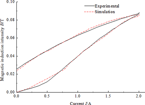
Figure 1. Measured magnetic hysteresis curve and the fitting curve generated by Jiles-Atherton model (Ms = 1.24 × 10⁶, a = 2.68× 10⁴, α = 1.47 × 10⁻⁴, c = 0.54, k = 5.69× 10³).
In order to reduce or eliminate the obvious hysteresis non-linearity between the control current of the MR damper and the magnetic flux intensity in the effective damping channel, a control method of hysteresis compensation is proposed in this paper. First of all a relationship of the theoretical optimal adjustable damping force Fτ(t) and the desired magnetic flux density Bd(t) was derived by calculation (Erol et al., 2012). As shown in Figure 2, the error e(t) between the theoretical magnetic flux density Bd(t) and the measured magnetic flux density Bm(t) is derived. Then the error is as the input of the PID (Proportional-Integral-Derivative) controller. The PID controller outputs the control current to the coils of the MR damper or J-A model.
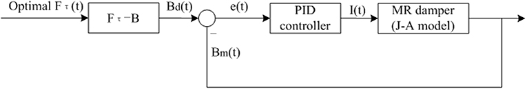
Figure 2. Schematic of PID control of the magnetic compensation control for a MR damper.
PID control is a traditional control strategy which is easy to realize and widely used in the industry automatic control system. In a control system, Equation (8) indicates the relationship of the output signal u(t) and the error signal e(t):
Where, KP is the proportional coefficient, KI is the integral coefficient and KD is the derivative coefficient. For PID controller, u(t) is the controlled value. Defining TI as integral time constant and TD as derivative time constant. The relationships of time constants and coefficients can be expressed as follows:
and
The proportional element in PID controller represents the speed of the control system. The larger the KP the faster the response speed of the system is and the higher the adjustment precision is, but it may cause overshoot and oscillation. On the contrary, the system response is slow. The integral element represents the accuracy of the control system. The integral term is introduced to make up for the defect that proportional control cannot eliminate steady-state error. When the error is integrated, the integral effect will increase with the increase of time and the output of the controller will be increased so that the steady-state error will be further reduced to zero. If the integral time constant TI is small, it means that the integral effect is strong, and vice versa, the weaker. However, if the integral coefficient KI is too large, the dynamic performance of the system will deteriorate and the overshoot and oscillation will occur. Hence, the stability of the system will be reduced. The differentiation of errors reflects the rate of variation of errors, that is, the trend of system errors. Because the phase angle of the differential element is ahead, when the error becomes larger, the differential of the error is greater than zero. And when the error decreases, the differential of the error is less than zero. So the differential control can produce the effect of early correction. When the error increases or decreases, the differential control will change the trend and reduce the error ahead of time so that the response speed of the system will be accelerated and the adjustment time will be reduced. So the differential control makes the system has good dynamic performance. But differential control needs to be used properly, otherwise the system will oscillate. In order to avoid oscillation, the value of differential coefficient KD is usually small (Li and Wang, 2012). The proportion coefficient, integral coefficient, and differential coefficient affect the control effect together. Reasonable adjustment of three parameters of Kp, KI, and KD is the key of the effectiveness of PID controller.
The J-A model of the magnetic hysteresis non-linearity of the MR damper above is utilized here to establish a control model in Simulink. The simulation model of the magnetic hysteresis control of a MR damper is shown in Figure 3. Figure 3A is the open-loop control system that means there is no magnetic flux density signal feedback. Figure 3B is the PID control system that means the magnetic flux density signal feedback and the PID controller works. In the feedback system, the module of Memory is employed to solve the problem of algebraic loop which will reduce the simulation speed or even reduce the accuracy of the simulation results or result in error results. As the constant δ in the Equation (3), the differential equation of the J-A model, is a symbol function which is inconvenient for derivation. Hence, the derivate module is not used in the magnetic hysteresis compensation control system.
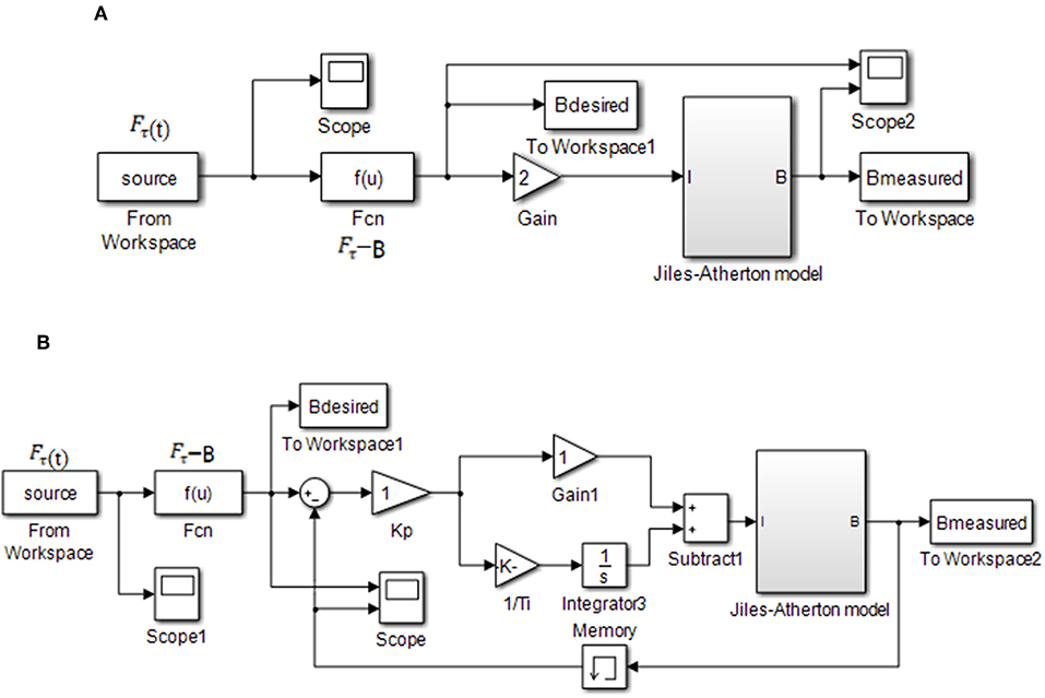
Figure 3. Simulation block diagram of magnetic hysteresis compensation control of a MR damper. (A) Open-loop control. (B) PID control.
The experimental setup of the magnetic hysteresis compensation control for the MR damper is mainly composed of a MR damper embedded in Hall sensor, acquisition device, current driver, DC power supply, test interface as shown in Figure 4.
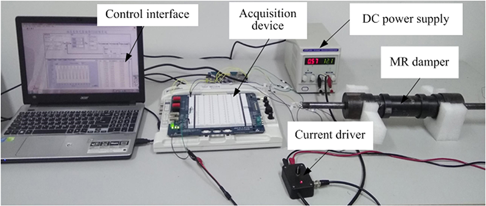
Figure 4. Experimental setup of the magnetic hysteresis compensation control for the MR damper.
ELVIS (National Instruments Corporation) suite is adopted as the hardware of data acquisition device. ELVIS is an educational laboratory virtual instrumentation suite as well as a common used high performance data acquisition card. The maximum sampling frequency of ELVIS is 1 MS/s and the resolution of analog input is 16 bit. The resolution of analog output is 16 bit as well. The function of analog + output is to output the control voltage to the current driver which is controlled by voltage of 0–5 V. The current driver (Lord, RD-3003-03) output current of 0–2 A according to the analog output of ELVIS. The control interface software is programmed by LabVIEW as shown in Figure S2. As the experiments with open-loop control is used to compare with the experiments with PID control, the relative software interfaces are designed and programmed, respectively.
The MR damper embedded in a Hall sensor is designed specially for research of the magnetic hysteresis control as shown in Figure 5. As we can see from Figure 5A, the Hall sensor (Allegro, A1304) is pasted in the cylinder surface of the piston.
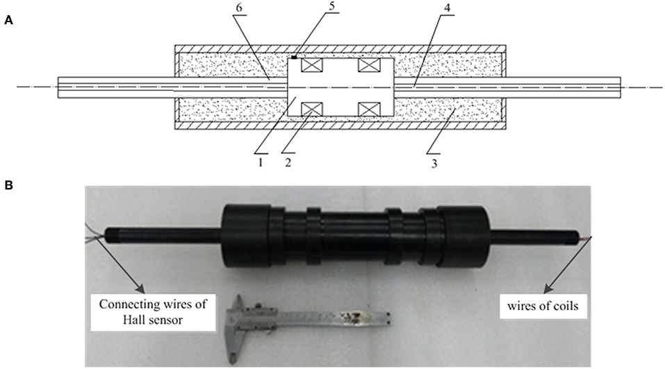
Figure 5. MR damper with embedded in Hall sensor. (A) Schematic of the MR damper (1) piston, (2) coil, (3) MR fluid, (4) fairlead hole, (5) Hall sensor, and (6) piston rod. (B) Picture of the MR damper.
A1304 linear Hall-effect sensor IC outputs analog signal which is convenient for data acquisition. It provides a miniature and low profile surface mount package as shown in Figure S3. A small plane is filed on the cylinder surface of the piston in order to mount the sensor. The branded face of the sensor IC is pasted firmly on the plane of the piston utilizing adhesive. As can be seen, the height of the IC is 1 mm so that it can be mounted on the piston which moves within the small gap of 2 mm. Hence, the miniature and low profile of the sensor IC is in favor of its mount. The footprints of Hall sensor and their connecting cables are covered with sheaths to insulation. The Hall sensor and the two coils of the MR damper are sealed by epoxy resin. The MR damper consists of a mono-tube and a two-ended piston with two stage coils. Because both the wire of the coils and the connecting wire of the sensor IC are needed to lead out of the MR damper, the double-ended piston is suitable for the MR damper embedded Hall sensor. The two-ended piston rods are hollow. The wires of the coils is leaded out from one end of the piston rod and the conducting wires connected to the footprints of the Hall-sensor IC is leaded out from the other end of the piston rod as shown in Figure 5B.
For the MR damper in this paper is designed and manufactured specially for verify the magnetic hysteresis compensation control method, both the dimension and the damping force is designed small. The structural dimensions of the MR damper are shown in Table 1.
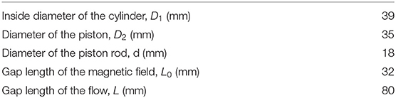
Table 1. Structural dimensions of the MR damper.
The adjustable damping force Fτ is a non-linear but single-valued function of magnetic induction intensity B. For comparison, the desired magnetic induction intensity instead of optimal adjustable damping force in Figure 2 is given as several typical signals of window function, multistep function, semi-sinusoidal function, and semi-sinusoidal functions with variable amplitude. The maximum amplitude of every simulation signal is set as 1 Tesla so that the relative magnetic hysteresis shows obviously in the curve. The simulation results of magnetic hysteresis compensation control of the MR damper are shown in Figure 6. The results in Figures 6A,C,E,G indicate that the magnetic induction intensity output by the MR damper cannot track the desired magnetic induction intensity after the signal start to decline in the open-loop control system. It is the reason that J-A magnetic hysteresis model established in the MR damper as shown in Figure 3. The results in Figures 6B,D,F,H show that the output signals of magnetic induction intensity can always track the changes of the input signals in the PID control system when KP = 0.5 and KI = 400. That means the PID control with appropriate coefficients can eliminate the effect of the magnetic hysteresis. The dynamic performance of the PID control system of MR damper is also obviously shown in Figures 6B,C. There is no overshoot in the dynamic process that partly leads to fast track of the output. The rising time is around 40 ms and the falling time is around 20 ms. The rising time and falling time in the simulation system are partly caused by the Memory module as shown in Figure 3 which leads to delay of the output. Moreover, the differential coefficient is zero. That means that there is no differential element in the PID control system. However, differential element can improve dynamic performance of the PID control system.
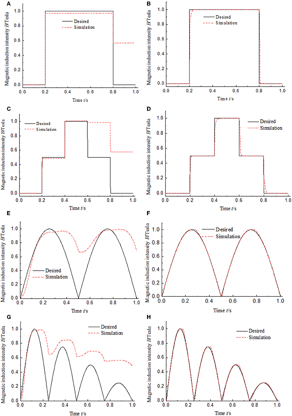
Figure 6. Simulation results of magnetic hysteresis control of the MR damper under the low frequency input signals. (A) Open-loop control under window function input signal. (B) PID control under window function input signal. (C) Open-loop control under multistep function input signal. (D) PID control under multistep function input signal. (E) Open-loop control under semi-sinusoidal function input signal. (F) PID control under semi-sinusoidal function input signal. (G) Open-loop control under semi-sinusoidal functions with variable amplitude input signal. (H) PID control under semi-sinusoidal functions with variable amplitude input signal.
As we know, the duration of the impact loading of the buffering system is short and always <0.1 s (Li and Wang, 2012). To verify whether the method of hysteresis compensation control can work well in a buffering system, four kinds of high frequency input signal is used for simulation. The simulation results are shown in Figure 7. Figures 7B,D,F,H show the PID control results of hysteresis compensation of MR damper under four kinds of high frequency input signals. The frequency of semi-sinusoidal signal is 200 Hz that means the time of one period is 0.05 s as shown in Figure 7F. Under the condition of high frequency input signal, the compensation effect of the PID control of hysteresis compensation is not different from that under the condition of low frequency input signal. The values of hysteresis are close to 0. That shows that the hysteresis compensation control method proposed in this paper is suitable for shock buffering system with short working period, and will be beneficial to improve the control accuracy of MR damper in shock buffering system. Under the condition of high frequency signal, the dynamic performance is also affected by Memory simulation module and lack of differential element as shown in Figure 7B. The rising response time is about 40 ms as same as that under low frequency input signal.
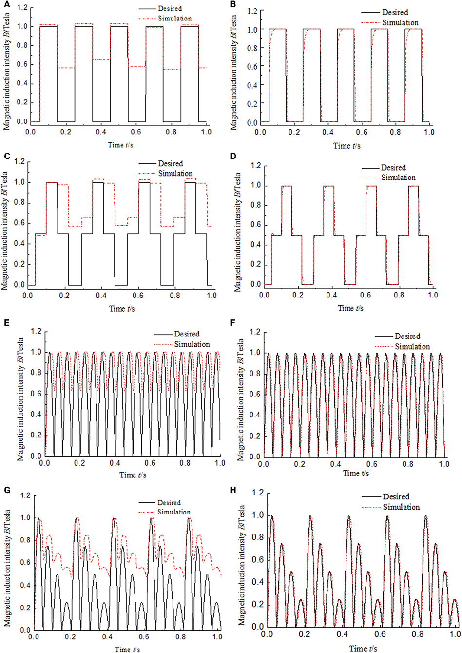
Figure 7. Simulation results of magnetic hysteresis control of the MR damper under the high frequency input signals. (A) Open-loop control under window function input signal. (B) PID control under window function input signal. (C) Open-loop control under multistep function input signal. (D) PID control under multistep function input signal. (E) Open-loop control under semi-sinusoidal function input signal. (F) PID control under semi-sinusoidal function input signal. (G) Open-loop control under semi-sinusoidal functions with variable amplitude input signal. (H) PID control under semi-sinusoidal functions with variable amplitude input signal.
The experimental results of magnetic hysteresis compensation control of the MR damper under four kinds of low frequency and high frequency input signals are shown in Figures 8, 9, respectively. The frequency of every kind of input signal is as same as that in the simulation system for comparison. In the experimental system, the input signal is the control current generated by the current deriver as shown in Figure 4. The experimental results shown in Figures 8, 9 indicate that the hysteresis under the PID control is almost completely compensated under both low frequency and high frequency input signals. Compared with the simulation results, the dynamic performances of the experimental results have been significantly improved. The response time is much shorter than that in simulation. The maximum response time is around 15 ms. The reason is that the experimental system does not include the Memory simulation module. It also reveals that the response time of the simulation system is mainly caused by the delay of the simulation module.
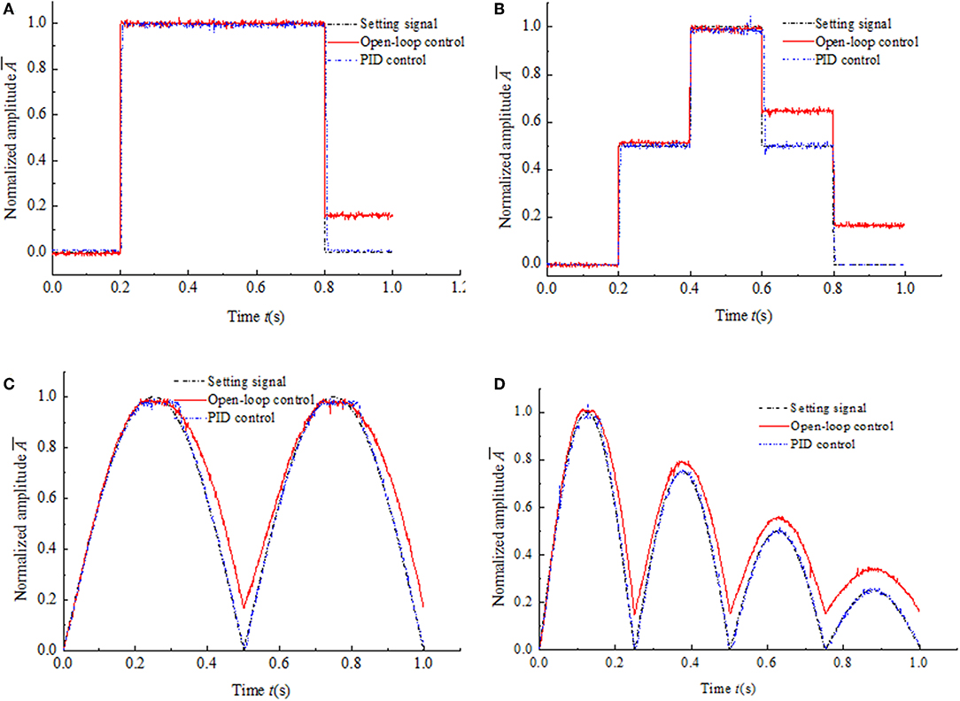
Figure 8. Experimental results of magnetic hysteresis control of the MR damper under the low frequency input signals. (A) Window function input signal. (B) Multistep function input signal. (C) Semi-sinusoidal function input signal. (D) Semi-sinusoidal functions with variable amplitude input signal.
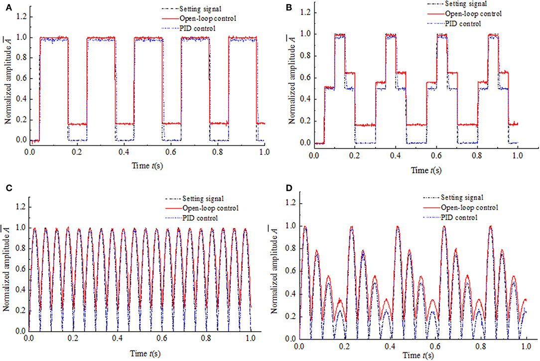
Figure 9. Experimental results of magnetic hysteresis control of the MR damper under the high frequency input signals. (A) Window function input signal. (B) Multistep function input signal. (C) Semi-sinusoidal function input signal. (D) Semi-sinusoidal functions with variable amplitude input signal.
The LabVIEW software generates the four kinds of typical signals as the setting values of the control system, respectively. Then the setting values convert to the analog voltage from the digital value by the DAQ device. Taking the analog voltage signals as the input of the experimental hysteresis compensation control system, the unit of the input signals is Volts and the voltage range is 0–5 V. The output signal of the experimental system is the output voltage of the Hall sensor. The voltage range of the Hall sensor is 0–3.3 V. Hence, the normalized amplitudes of the input and the output are plot in Figures 8, 9 for comparison.
A typical MR impact buffer system can be descripted as a MR damper and a mass as shown in Figure S4. The MR damper outputs damping force Fmr which consists of uncontrollable part Fμ and controllable part Fτ. Fμ is related to the velocity of the piston of the MR damper. While Fτ is related to the magnetic flux density of the effective damping channel.
According to Newton's second law, the motion equation of the system can be descripted as
where Fpt is the impact force loaded on the mass. m is the mass of the object subjected to the impact loading. x is the displacement of the mass.
The ideal impact buffer effect is obtained when the damping force equals to constant (Li and Wang, 2012) as shown
where Fmr_i is the ideal damping force and c1 is the coefficient determined by the dimension of the MR damper.
According to the impact loading in the gun recoil system (Li and Wang, 2012), the impact force as shown in Figure S5 is given to verify the effect of the hysteresis compensation control.
Combine Equations (11) and (12), the ideal displacement x(t) and the ideal velocity ẋ(t) can be obtained by solving the second order differential equation. Assuming the ideal damping force Fmr_i equals to 4,000 N, the ideal controllable damping force Fτ can also be obtained as shown in Figure 10. The impact buffer motion starts when the impact force loaded in the mass and the motion ends when the velocity of the mass changes to 0. As we can see, the calculated ideal controllable damping force Fτ changes within 0.07 s. That means the control current needs to be changed quickly. Fast change of the current leads to the obvious decrease in performance of the system caused by the magnetic hysteresis. Hence, the magnetic hysteresis of the MR damper in the impact buffer system will inevitably reduce the buffer effect.
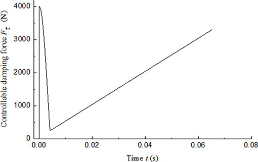
Figure 10. Ideal controllable damping force.
The model of the MR-damper-based impact buffer system is established and the simulation block diagrams of MR impact buffer system including magnetic hysteresis model are shown in Figure 11. The mechanical model and the magnetic hysteresis model of the MR damper are both included in the simulation system. Although the ideal damping force is as a condition of the calculation for Equation (11), the actual output damping force of the MR damper is not constant for the existence of the magnetic hysteresis. Figure 11A shows open-loop control and Figure 11B shows PID control. In Figure 11B, the magnetic flux density of the MR damper is fed back for obtaining the error of the ideal magnetic flux density and the actual magnetic flux density as the input of the PID controller.
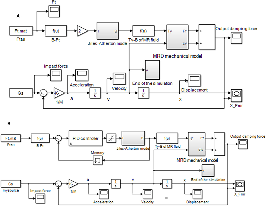
Figure 11. Simulation block diagram of MR impact buffer system including magnetic hysteresis model. (A) Open-loop control. (B) PID control.
The simulation results of the MR impact buffer system under open-loop control and PID control are obtained as shown in Figures 12, 13, respectively. For the impact buffer system, the relationship of the actual damping force and time or the relationship of the actual damping force and displacement of the mass is used to evaluate the buffer performance. The closer the curve is to the constant, the better the buffer performance will be. Figures 12C,D indicates that the peak damping force is much larger than the ideal value 4,000 N and is not keep constant in the whole buffer process under open-loop control. Figures 13C,D shows that a peak damping force still exists at the very beginning buffer process under PID control. While the value of the peak damping force under PID control is much less than that under open-loop control.
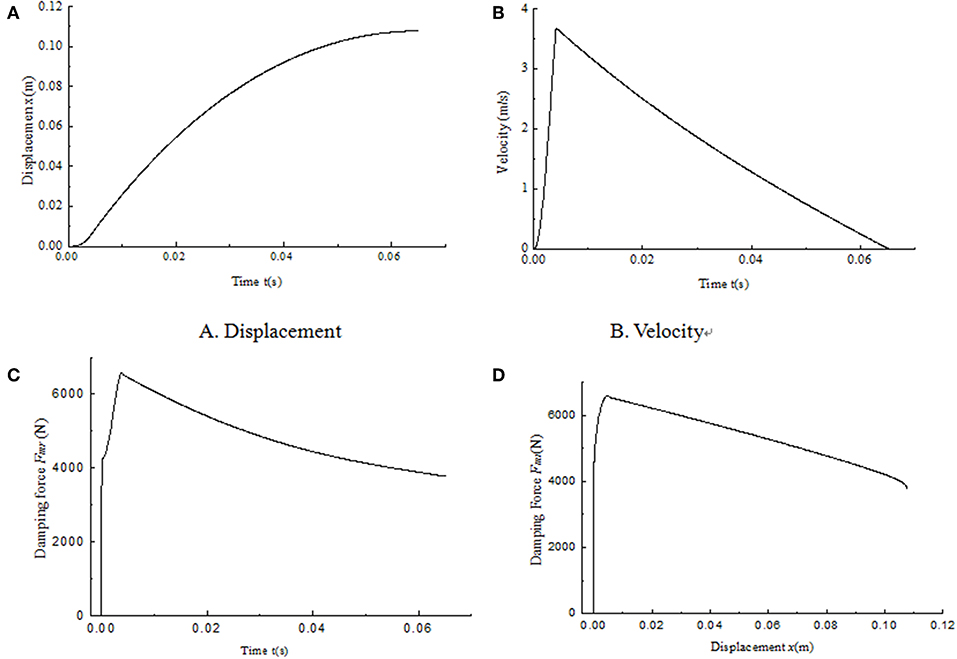
Figure 12. Simulation results of the MR impact buffer system under open-loop control. (A) Displacement. (B) Velocity. (C) Damping force. (D) Damping force vs. displacement.
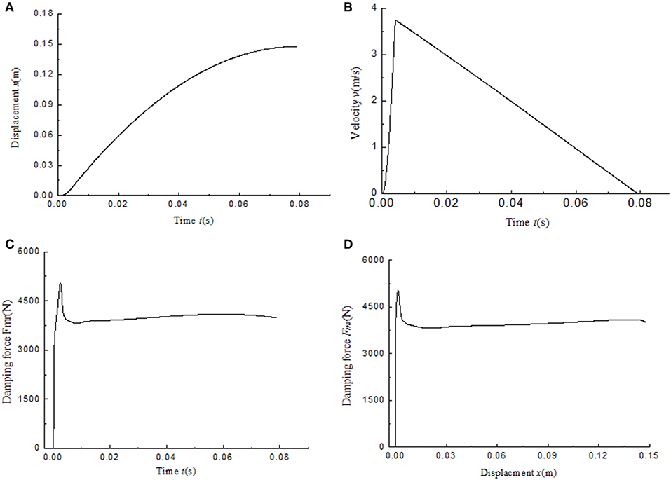
Figure 13. Simulation results of the MR impact buffer system under PID control. (A) Displacement. (B) Velocity. (C) Damping force. (D) damping force vs. displacement.
For comparison, the curves of the damping force and the displacement under two control methods are shown together as shown in Figure 14. As we can see, the damping force under PID control is similar to constant mostly except for the part at the very beginning of the buffer process. The damping force under open-loop control can't keep constant during the whole buffer process. The results indicate the magnetic hysteresis of the MR damper decreases the buffer performance and the PID control based on magnetic flux density feedback can greatly compensate the effect of the hysteresis.
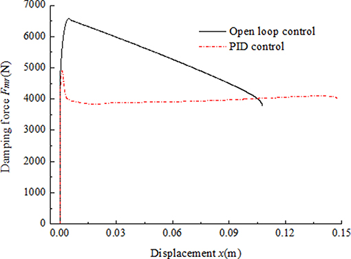
Figure 14. Comparison of impact buffer effect under two different control methods.
In this research, the magnetic hysteresis compensation control method for MR damper was investigated. Jiles-Atherton model was employed to descript the magnetic hysteresis non-linearity of the MR damper. A MR damper embedded in a Hall sensor was designed and manufactured for verify the effective of the magnetic hysteresis compensation control method proposed in this paper. A PID controller is employed in the hysteresis compensation system to adjust the performance of the magnetic induction intensity feedback system. The numerical simulation proved the feasibilities of the PID control of the magnetic hysteresis compensation system of the MR damper under both low frequency input and high frequency input. The experimental setup was established by integrating the MR damper embedded in a Hall sensor and the measurement, control device, and software interface. The experimental results show that the measured magnetic induction intensity can track the input signal well under any of the four kinds of setting signals both with low frequency and high frequency by PID control. This means that the effect of magnetic hysteresis was nearly completely eliminated by PID controller. At the same time, the dynamic performance of the experimental magnetic hysteresis system is good with no overshoot and fast response speed. In order to verify the effect of the proposed hysteresis compensation control method in the MR impact buffer system, a simulation model of the MR-damper-based impact buffer system is established. The results show that the impact buffer system with PID control obtains the better buffer performance than that with open-loop control. It means the proposed hysteresis compensation method in this paper is suitable for the shock buffering system with a MR damper to improve the buffering performance of the system subject to impact loadings.
The datasets generated for this study are available on request to the corresponding author.
ZL proposed the magnetic hysteresis compensation method, designed the MR damper embedded in a Hall sensor, and conducted the experiments. YG carried out the simulation of the hysteresis compensation control of the MR damper and conducted the experiments. SL processed and analyzed the experimental data. WW designed the MR damper embedded a Hall sensor and tested the basic performance of the MR damper.
This work was supported by National Natural Science Foundation of China (NSFC) grant funded by the Chinese Government (No. 51305207) and Natural Science Foundation of Jiangsu Provincial College (Grand Nos. 13KJB460010 and 17KJB413002).
The authors declare that the research was conducted in the absence of any commercial or financial relationships that could be construed as a potential conflict of interest.
The Supplementary Material for this article can be found online at: https://www.frontiersin.org/articles/10.3389/fmats.2019.00299/full#supplementary-material
Figure S1. Magnetic hysteresis curve plotted by Jiles-Atherton model (Ms = 1.25 × 10⁶, a = 1,100, α = 0.0017, c = 0.5, k = 400).
Figure S2. Software interface of magnetic hysteresis compensation control of MR damper utilizing LabVIEW. (A) Open-loop control. (B) PID control.
Figure S3. Schematic of Hall sensor (Allegro, A1304). (A) Top view. (B) Side view.
Figure S4. The MR impact buffer system.
Figure S5. Impact force loaded on the impact buffer system.
An, J., and Kwon, D. S. (2003). Modeling of a magnetorheological actuator including magnetic hysteresis. J. Intell. Mater. Syst. Struct. 14, 541–550. doi: 10.1177/104538903036506
Bai, X. X., Shen, S., Wereley, N. M., and Wang, D. H. (2018). Controllability of magnetorheological shock absorber: I. Insights, modeling and simulation. Smart Mater. Struct. 28:015022. doi: 10.1088/1361-665X/aaf072
Carlson, J. D. (2002). What makes a good MR fluid? J. Intell. Mater. Syst. Struct. 13, 431–435. doi: 10.1106/104538902028221
Choi, S. B., Nam, M. H., and Lee, B. K. (2000). Vibration control of a MR seat damper for commercial vehicles. J. Intell. Mater. Syst. Struct. 11, 936–944. doi: 10.1106/AERG-3QKV-31V8-F250
Coleman, B. D., and Hodgdon, M. L. (1986). A constitutive relation for rate-independent hysteresis in ferromagnetically soft materials. Int. J. Eng. Sci. 24, 897–919. doi: 10.1016/0020-7225(86)90023-6
Dyke, S. J., Spencer, B. F. Jr, Sain, M. K., and Carlson, J. D. (1998). An experimental study of MR dampers for seismic protection. Smart Mater. Struct. 7, 693–703. doi: 10.1088/0964-1726/7/5/012
Erol, O., Gonenc, B., Senkal, D., Alkan, S., and Gurocak, H. (2012). Magnetic induction control with embedded sensor for elimination of hysteresis in magnetorheological brakes. J. Intell. Mater. Syst. Struct. 23, 427–440. doi: 10.1177/1045389X11435432
Goncalves, F. D., Ahmadian, M., and Carlson, J. D. (2006). Investigating the magnetorheological effect at high flow velocities. Smart Mater. Struct. 15, 75–85. doi: 10.1088/0964-1726/15/1/036
Hodgdon, M. L. (1988). Applications of a theory of ferromagnetic hysteresis. IEEE Trans. Magn. 24, 218–221. doi: 10.1109/20.43893
Jedryczka, C., Sujka, P., and Szelag, W. (2009). The influence of magnetic hysteresis on magnetorheological fluid clutch operation. COMPEL Int. J. Comput. Math. Electr. Electr. Eng. 28, 711–721. doi: 10.1108/03321640910940963
Jiles, D. C., and Atherton, D. L. (1986). Theory of ferromagnetic hysteresis. J. Magn. Magn. Mater. 61, 48–60. doi: 10.1016/0304-8853(86)90066-1
Jolly, M. R., Bender, J. W., and Carlson, J. D. (1998). “Properties and applications of commercial magnetorheological fluids,” in SPIE 5th Annual International Symposium on Smart Structures and Materials (San Diego, CA).
Joseph, D. S. (2001). Parameter Identification for the Preisach Model of Hysteresis (Doctoral dissertation). Blacksburg, VA: Virginia Tech.
Li, Z., and Gong, Y. (2019). Research on ferromagnetic hysteresis of a magnetorheological fluid damper. Front. Mater. 6:111. doi: 10.3389/fmats.2019.00111
Li, Z., Gong, Y., and Wang, J. (2019). Optimal control with fuzzy compensation for a magnetorheological fluid damper employed in a gun recoil system. J. Intell. Mater. Syst. Struct. 30, 677–688. doi: 10.1177/1045389X17754258
Li, Z. C., and Wang, J. (2012). A gun recoil system employing a magnetorheological fluid damper. Smart Mater. Struct. 21:105003. doi: 10.1088/0964-1726/21/10/105003
Preisach, F. (1935). Über die magnetische nachwirkung. Zeitschr. Phys. 94, 277–302. doi: 10.1007/BF01349418
Sahasrabudhe, S. S., and Nagarajaiah, S. (2005). Semi-active control of sliding isolated bridges using MR dampers: an experimental and numerical study. Earthquake Eng. Struct. Dyn. 34, 965–983. doi: 10.1002/eqe.464
Seong, M. S., Choi, S. B., and Han, Y. M. (2009). Damping force control of a vehicle MR damper using a Preisach hysteretic compensator. Smart Mater. Struct. 18:074008. doi: 10.1088/0964-1726/18/7/074008
Shou, M., Liao, C., Zhang, H., Li, Z., and Xie, L. (2018). Modeling and testing of magnetorheological energy absorbers considering inertia effect with non-averaged acceleration under impact conditions. Smart Mater. Struct. 27:115028. doi: 10.1088/1361-665X/aae6a0
Wang, D. H., and Liao, W. H. (2011). Magnetorheological fluid dampers: a review of parametric modelling. Smart Mater. Struct. 20:023001. doi: 10.1088/0964-1726/20/2/023001
Wang, K., Zhang, Y., and Jones, R. W. (2010). “Modelling of hysteresis in smart actuators using the generalised Prandtl-Ishlinskii operator,” in ICCAS 2010 (Gyeonggi-do: IEEE), 261–266.
Wang, X., and Gordaninejad, F. (2007). Flow analysis and modeling of field-controllable, electro-and magneto-rheological fluid dampers. J. Appl. Mech. 74, 13–22. doi: 10.1115/1.2166649
Wereley, N. M., Choi, Y. T., and Singh, H. J. (2011). Adaptive energy absorbers for drop-induced shock mitigation. J. Intell. Mater. Syst. Struct. 22, 515–519. doi: 10.1177/1045389X10393767
Keywords: MR fluid damper, hysteresis non-linearity, compensation control, shock buffering system, PID control
Citation: Li Z, Gong Y, Li S and Wang W (2019) Magnetic Hysteresis Compensation Control of a Magnetorheological Damper. Front. Mater. 6:299. doi: 10.3389/fmats.2019.00299
Received: 27 July 2019; Accepted: 08 November 2019;
Published: 05 December 2019.
Edited by:
Xian-Xu Bai, Hefei University of Technology, ChinaReviewed by:
Donghong Ning, University of Wollongong, AustraliaCopyright © 2019 Li, Gong, Li and Wang. This is an open-access article distributed under the terms of the Creative Commons Attribution License (CC BY). The use, distribution or reproduction in other forums is permitted, provided the original author(s) and the copyright owner(s) are credited and that the original publication in this journal is cited, in accordance with accepted academic practice. No use, distribution or reproduction is permitted which does not comply with these terms.
*Correspondence: Zhaochun Li, bHpjLmhuQDE2My5jb20=
Disclaimer: All claims expressed in this article are solely those of the authors and do not necessarily represent those of their affiliated organizations, or those of the publisher, the editors and the reviewers. Any product that may be evaluated in this article or claim that may be made by its manufacturer is not guaranteed or endorsed by the publisher.
Research integrity at Frontiers
Learn more about the work of our research integrity team to safeguard the quality of each article we publish.