 Hasan Al Ba'ba'a
 Jesse Callanan
 Mostafa Nouh
- Department of Mechanical and Aerospace Engineering, University at Buffalo (SUNY), Buffalo, NY, United States
Rejection of unmitigated vibrational disturbances represents an ongoing dilemma in complex linkage systems. In this work, we present an inherent and self-reliant vibration isolation mechanism in architected periodic chains of serially pivoted pendulums. Absorption of external excitations is achieved by virtue of Bragg-type band gaps which stem from the emergent chain dynamics. Owing to its coupled dynamics, the self-repeating cell of a Phononic Crystal (PC) is not trivial and cannot be readily identified from the periodic arrangement by inspection. As such, this work entails the extraction of a “pseudo” unit cell of an equivalent PC lattice from the derived motion equations of a finite chain, which departs from traditional wave dispersion methods. The model presented herein comprises a chain of linked pendulums with periodic variations of inertial/geometrical properties, carrying a payload at one end. We ultimately show evidence of forbidden wave propagation in prescribed frequency regimes, reminiscent of band gaps in PC lattices. The emergence of such gaps is experimentally demonstrated and shown to be in good agreement with the predicted wave dispersion behavior. The presented framework can be invaluable in applications that require vibration reduction in the delivery of payloads including gantry cranes, robotic arms and space tethers.
1. Introduction
Undesirable vibrations and mechanical disturbances are an ever-lasting concern in the vast majority of engineering applications. The effect of vibrations on a dynamical system ranges from shortening its lifetime to sudden ruptures, all of which impose serious operational challenges. The rational design of architected structures provides unique mechanisms by which unwanted arbitrary excitations can be rejected with minimal, and often non-existent, compromises in strength and resilience. Structural periodicity, whether in material composition (Ruzzene and Baz, 2000), topology (Bilal and Hussein, 2011), boundary conditions (Al Ba'ba'a et al., 2017), placement of local resonances (Pai et al., 2014) or via combinations of the previous (Liu and Hussein, 2012; Bacquet et al., 2018), enables a myriad of unprecedented wave dispersion capabilities; tailored to address challenges in vibroacoustic mitigation. Single and double negative materials (Li and Chan, 2004; Huang et al., 2009), wave directivity (Celli and Gonella, 2015), mechanical topological insulators (Pal et al., 2018), and one-way elastic diodes (Trainiti and Ruzzene, 2016) are a few prime characteristics of engineered periodic systems.
This effort focuses on applications comprising mechanical pendulums and pendulum-like substructures suspended from a pivot and tasked with carrying and/or conveying a payload. Specifically, we address chains of coupled pendulums, the dynamics of which lie at the heart of several applications such as flexible robotic arms (Giorgio and Del Vescovo, 2018), unmanned aerial vehicles with payloads (Goodarzi et al., 2015) and gantry (overhead) cranes (Masoud and Alhazza, 2017). In the latter, for instance, vibrations can be detrimental to the positioning accuracy of the terminal payload location. They elevate the conveyance duration of payloads and, consequently, create an operational bottleneck (Abdel-Rahman et al., 2003). The pendular motion of the payload has been by far regulated using active control techniques, exploiting tools such as command shaping (Masoud and Alhazza, 2017) and feedback control (Masoud and Nayfeh, 2003). In its most common form, payload is often hoisted via a rope or a linkage chain and is transported via a cart/trolley (see left panel of Figure 1). The mechanism of the chain variant resembles that of a pendulum chain, where the tip of an individual pendulum (link) acts as a pivot to the subsequent one. Incorporating pendulums in novel metastructures has recently received increased attention. The most dominant example being one-dimensional arrays of pendulums periodically coupled with springs which have been utilized to study a variety of intriguing phenomena pertaining to nonlinear oscillators. These include solitons (Jallouli et al., 2017), breathers (Russell et al., 1997), energy transmission in band gaps (Geniet and Leon, 2002) and most recently helical edge states in topological insulators (Süsstrunk and Huber, 2015). To this end, however, exploiting the periodicity of pendulum chains as an inherent and self-reliant mechanism for vibration absorption remains uncharted territory. The aim of this work is to fill this gap by demonstrating phononic-like phenomena in the wave propagation profiles of such chains. Through a closed-form analysis of the dynamics of a periodic lumped pendulum chain with a payload (tip mass), as portrayed in Figure 1, we ultimately show evidence of emergent phononic band gaps. Such gaps, resulting from Bragg-scattering and interference effects, restrict the propagation of waves within certain (and ultimately favorable) frequency regimes.
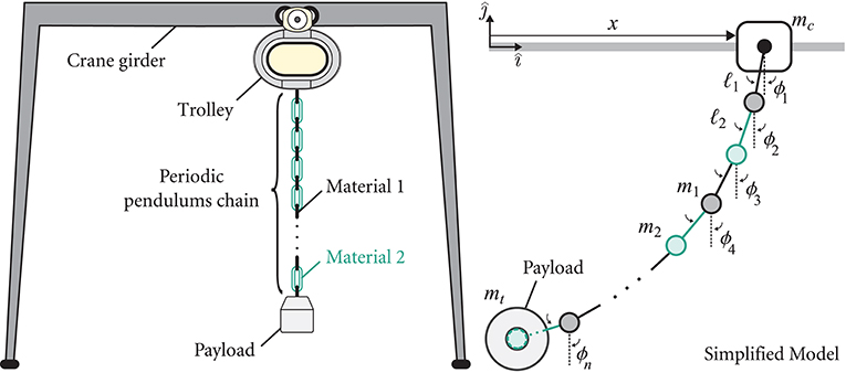
Figure 1. A schematic of a gantry crane system with a periodic pendulum chain with an end payload (Left) and a corresponding simplified pendulum chain model with a tip mass (Right).
Although the parameters of the chain of pendulums are periodic, the dynamics of each concentrated mass is strongly coupled with the whole chain as dictated by its motion equations (Masoud and Alhazza, 2017). As a result, the self-repeating unit cell of the chain arrangement (e.g., two masses m1, 2 and their links ℓ1, 2 in a diatomic configuration as shown in Figure 1) cannot be readily defined by the naked eye. As such, the most significant challenge unraveled here is the identification of a “pseudo” unit cell for Bloch-wave dispersion purposes and ultimately validating this cell choice from the actual pendulum response. Such identification process naturally departs from the conventional approach and instead relies on the dynamics of the finite chain as a reference point. We start by deriving the equations of motion for a general chain of pendulums; the generalized model serves as the baseline for studying three distinct scenarios: (1) A uniform chain with and without a tip mass, (2) A chain with periodic variation of masses with a tip mass, and (3) A chain with periodic variation of the linkage lengths and carrying a tip mass. We mathematically show that the tip mass is crucial in order to obtain a unit cell representation of an equivalent PC lattice which accurately captures the behavior of the chain under small vibrational amplitudes. The equivalent PC model is then compared with the actual linearized model of the periodic chain of pendulums in frequency and time domains. The latter is finally used to reconstruct the wave dispersion contours of the actual system, which validates the equivalent model for all three cases. We conclude with an experimental validation of the emerging band gaps in the pendulum chain, including transfer function measurements over a frequency sweep as well as a visual presentation of the spatial wave profile inside and outside the band gap.
2. Generalized Equations of Motion
For a chain of pendulums with masses mi connected by rigid connections with length ℓi, the position vector r for the ith mass is given by
and, hence, its velocity vector is
where is the time derivative, and are directional unit vectors, respectively, and the angles ϕj are labeled on the right panel of Figure 1. Following which, the potential energy of the pendulum chain can be expressed as
while the kinetic energy, , is given by
The Euler-Lagrange equation, i.e., , where is the Lagrangian of the system, requires the evaluation of the partial derivative of the Lagrangian with respect to the angular position and velocity of the ith mass, i.e.,
which leads to the equation of motion of the ith mass of the system, given by
Equation (8) serves as a generic equation of motion for the ith mass for any arbitrary set of parameters and number of masses in the pendulum chain. Assuming small oscillations, i.e., ϕi ≈ 0, Equation (8) can be linearized and written as
Using Equation (9) and setting the cart's acceleration, i.e., , as an input, the equations of motion of the entire chain can be cast into a compact matrix form as
where
3. Dynamics of Periodic Pendulums
3.1. Case I: Uniform Chain
For a uniform chain with identical link lengths and lumped masses, i.e., ℓi = ℓ and mi = m, but without a tip mass, the linearized equation of motion of the ith mass given by Equation (9) reduces to
where , which leads to the following system of equations:
where
The inverse of a matrix with the structure of M in Equation (14a) has been shown to be a tridiagonal matrix (da Fonseca and Petronilho, 2001; da Fonseca, 2007). For the uniform pendulum chain, the inverse of the matrix M in Equation (14a) is derived as
Upon multiplying Equation (13) by M−1, it simplifies to
where
and the forcing term reduces to . By inspecting Equation (17), it is evident that the structure of D is not periodic even though the physical chain has uniform properties. Consequently, a substructure consisting of one mass and its adjacent massless link cannot be considered a self-repeating unit cell of the system for Bloch-wave analysis. Next, consider the same chain of masses with a tip mass mt at its end such that mt = ϱm. The linearized equation of motion of the ith mass now reads
Casting the equations of motion into a matrix form similar to the previous analysis, it can be deduced that the inverse of the mass matrix in this case becomes
Now, if the payload is much heavier than the rest of the masses chain, i.e., , then the stiffness matrix can be approximated as K ≈ ϱI with I being the unit matrix; the equations of motion now reads:
such that . Upon normalization using ω0, we arrive at the following reduced non-dimensional set of motion equations:
where and τ = ω0t. This system of equations identically resembles that of a monatomic lattice with free-free boundary conditions (since as ϱ → ∞), and a repeating unit cell of an infinite medium can now be defined. The equivalent monatomic lattice comprises a chain of lumped masses m connected via springs . As such, the medium's dispersion relation can be derived as (Hussein et al., 2014)
where and are the dimensionless temporal and spatial frequencies, respectively. To verify these assumptions, we simulate the actual and equivalent systems in time and frequency domains. For the equivalent monatomic lattice, the end-to-end transfer function can be analytically derived as (see Al Ba'ba'a et al., 2018 for details)
where θi depends on the boundary conditions of the system and is equal to in this case (Yueh, 2005). The roots of the denominator of Equation (23) represent the system's poles (i.e., natural frequencies) and can be used to analytically determine the spectrum of the equivalent system. It can be seen that the rigid body mode at s = 0 cancels perfectly with the s2 term in the numerator; a result of the input being the acceleration of the cart, i.e., . Figures 2A,B show the frequency response for the system under consideration with ϱ = 102 and ϱ = 103 for both the equivalent and actual systems as well as the pole distribution in the complex s-domain. The results show excellent agreement between the equivalent and actual systems for ϱ = 103 while the frequency response and the pole distribution of the equivalent system slightly deviate from the actual one when ϱ = 102.
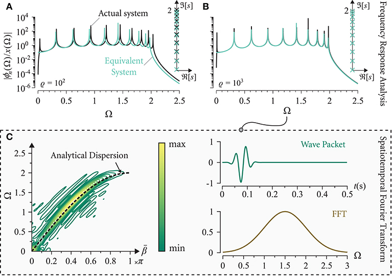
Figure 2. Frequency response diagrams and corresponding pole distribution for (A) ϱ = 102 and (B) ϱ = 103 for a uniform chain of pendulums with n = 10. (C) Numerical dispersion contours constructed from the actual chain of pendulums (n = 31) showing agreement with the analytical dispersion branch (black dashed-line) obtained from the equivalent system via Equation (22). (Spectral and transient properties of the excitation are provided for reference).
To validate the dispersion analysis in Equation (22), on the other hand, the system is excited with a wide band excitation and its dispersion profile is constructed from the time-transient response of the system using the spatiotemporal Fourier transform (Airoldi and Ruzzene, 2011). Figure 2C depicts the numerical dispersion contours for a chain of n = 31. The analytical dispersion relation of the equivalent system, i.e., Equation (22), is displayed as a dashed line for comparison and shows a very decent agreement.
3.2. Case II: Periodic Variation in Masses
The previous results for the uniform chain of pendulums can be extended to a chain with a periodic arrangement of masses, as portrayed in Figure 3A. Assume that the odd numbered masses are m1 = m while the even numbered are m2 = μm, where is the mass ratio. Making use of Equation (9) and with few mathematical manipulations, the equations of motion simplify to Equation (13) with the following new definitions for M, K and f:
where ⌊·⌋ is the floor function and “mod” is the modulo operator. The mass matrix M in Equation (24a) has the following inverse (which is shown for an even n):
where for an even n while for an odd n, we get . Note that ϵ reduces to either unity or for an even or odd n, respectively, as ϱ → ∞ and μ = 1 recovers M−1 for the uniform chain of pendulums, i.e., Equation (19). Since the payload is assumed to be much larger than the masses in the chain, the approximation K ≈ ϱI remains intact leading to the equations of motion in Equation (21) for the equivalent system with M−1 defined in Equation (25). The resultant equations of motion resemble that of a conventional diatomic lattice (see Figure 3B) with identical masses, alternating springs, and free-free boundary conditions (Al Ba'ba'a et al., 2017). The unit cell can be now defined as two identical lumped masses m and two different springs and k2 = μk1, and, hence, the nondimensional dispersion relation for the equivalent system can be given by
with an emergent Bragg-type frequency band gap whose bounds are and . A detailed derivation of the dispersion relation is provided in Appendix 1. It is very intriguing to observe that the variation of the masses in the periodic pendulums influences the equivalent stiffness of the system and, as a result, the mass ratio μ now dictates the ratio between the stiffnesses in the equivalent system.
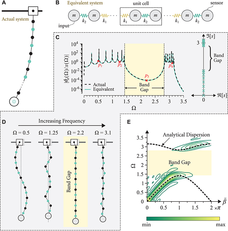
Figure 3. Schematic of (A) the actual pendulum chain with varying masses and (B) the equivalent diatomic lattice with varying stiffnesses. (C) Frequency response diagram for the actual and equivalent systems for n = 15, μ = 0.25, ϱ = 103 and ℓ = 1 (left) and its corresponding poles distribution (right). (D) An illustrative schematic of the steady state responses of the pendulums with varying masses at four distinct excitation frequencies (marked p1−4 on the frequency response). (E) Numerical dispersion contours constructed from the actual chain of pendulums showing agreement with the analytical dispersion relations (black dashed-line) obtained from the equivalent system via Equation (26).
In line with the analysis performed for the uniform pendulum chain, the frequency and time responses of the equivalent and actual systems are computed to validate these predictions. Analytical transfer functions for a diatomic lattice have been derived in literature for any arbitrary combination of design parameters (Al Ba'ba'a et al., 2017). For brevity, the derivation details are omitted here and we only show the final forms of the end-to-end transfer functions. For an even n, we obtain
while for an odd number n, the transfer function reads
where in both cases. For n = 15, μ = 0.25, ϱ = 103 and ℓ = 1, Figure 3C shows the frequency responses of the equivalent and actual systems and their corresponding pole distributions. An excellent agreement between the two realizations is clearly observed. Unlike the case of the uniform pendulums, the natural frequency spectrum is split into two distinct groups of natural frequencies, before and after the band gap range, both of which have an essential role in the formation of the band gap itself as detailed in literature (Al Ba'ba'a et al., 2017). The band gap range in the frequency response spans the range , which can be shown to match the band gap limits obtained from the dispersion relation in Equation (26).
The steady state responses of the periodic pendulum chain at different frequencies are shown in Figure 3D. Within the band gap at Ω = 2.2, the angular displacement corresponding to the payload at the tip of the chain is nearly zero, in addition to most of the chain masses prior to the payload, which is indicative of a band gap. On the other hand, the responses of the chain for Ω outside the range of the band gap clearly show a wave-like motion as expected from pass band frequencies. Finally, the dispersion behavior in Equation (26) is tested by simulating the system's transient response to a wave packet in the time domain, as illustrated earlier. Figure 3E shows the numerical dispersion contours for the same parameters used to generate Figure 3C but with n = 41. As depicted in the figure, the entirety of the pendulum chain's dispersion energy coincides with dispersion bands predicted from Equation (26).
3.3. Case III: Periodic Variation in Linkage Lengths
Consider the case of periodic pendulums with the lengths of odd and even numbered links being ℓ1 = ℓ and ℓ2 = κℓ, respectively, where κ is the length ratio of the periodic links; a visual illustration is provided in Figure 4A. As in the case of the periodically varying pendulums masses, the equations of motion simplify to Equation (13), albeit with the following M, K and f definitions:
and the inverse mass matrix in this case (shown for an even number n) is:
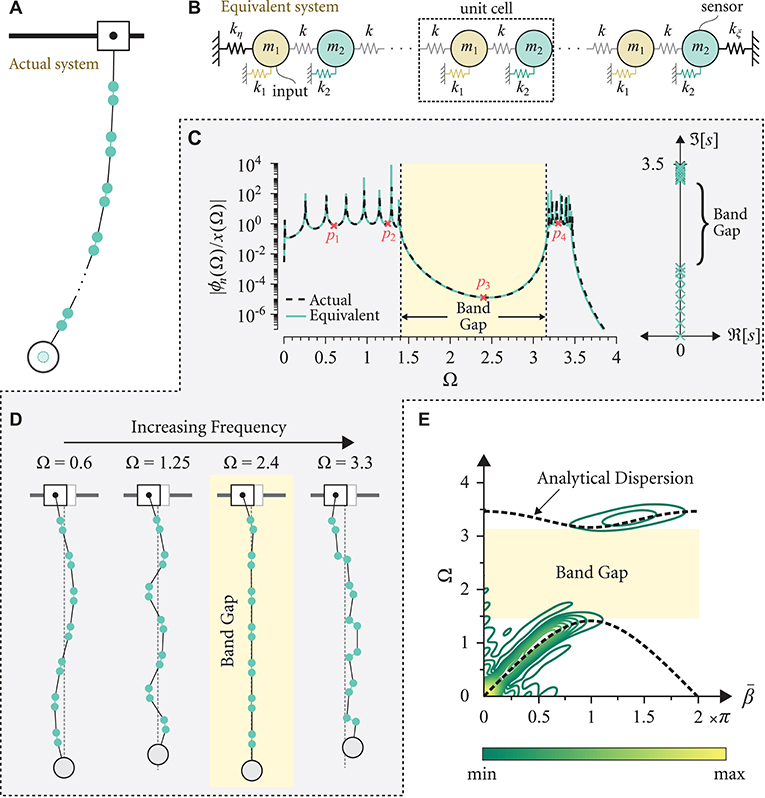
Figure 4. Schematic of (A) the actual pendulum chain with linkage variations and (B) its equivalent PC lattice. (C) Frequency response diagram for the actual and equivalent systems for n = 15, κ = 0.2, ϱ = 103 and ℓ = 1 (left) and its corresponding poles distribution (right). (D) An illustrative schematic of the steady state responses of the pendulums with varying linkage at four distinct excitation frequencies (marked p1−4 on the frequency response). (E) Numerical dispersion contours constructed from the actual chain of pendulums showing agreement with the analytical dispersion relations (black dashed-line) obtained from the equivalent system via Equation (32).
For an even n, while for an odd one, . Unlike the case of periodic masses, the stiffness matrix in Equation (29b) is approximated by a periodic diagonal matrix which is valid for a large ϱ value and, for an even n, is given by
Since M−1 acts as the stiffness matrix of an equivalent PC lattice, the inverse of K in Equation (31) can be treated as the equivalent mass matrix, and will ultimately yield the unit cell of the equivalent PC lattice. Observing the pattern of M−1 in Equation (30) and the inverse of K in Equation (31), it can be concluded that these matrices resemble the stiffness and mass matrices, respectively, for a diatomic lattice with periodic elastic foundations and varying masses, and with two boundary springs kη and kξ. For visualization, this arrangement is depicted in Figure 4B. Based on Equation (30), the equivalent PC has uniform springs of and the stiffness of the periodic elastic foundations are k1 = 2k(κ − 1) and , which implies that either k1 or k2 has to be negative depending on the value of κ. The latter is interesting since a negative stiffness is usually induced by active elements, e.g., piezoelectric shunts (Chen et al., 2014). In the present case, however, the negative stiffness is a direct consequence of the unique dynamics of the pendulum chain. Similarly, it can be shown that the spring constant for all n, while kξ = kη and for odd and even values of n, respectively. In addition to the periodic elastic foundation, the variation in the length of the links creates a periodic variation in the masses for the equivalent lattice with values m1 = m and m2 = m1/κ. For these values of springs and masses, and for the unit cell marked on the schematic given by Figure 4B, the following dispersion relation can be derived:
and the corresponding band gap bounds are and . Further details pertaining to this derivation are provided in Appendix 2.
Given the boundary conditions of this PC model, a closed-form analytical solution for the system's poles remains elusive. As a result, the frequency response in this scenario is derived in semi-analytical form since the poles of the system are calculated numerically. Once the poles are computed, the following equation depicts the system's transfer function for all n (see Miu, 1993 for more details):
In Equation (33), Ωi is a normalized pole of the system. For κ = 1/5, n = 15, ℓ = 1 and ϱ = 103, Figure 4C shows the end-to-end frequency response function for the actual and equivalent systems, where a very good match is observed. As expected, a band gap is created in the range which coincides with the large attenuation region in the frequency response diagram and matches the range predicted from the dispersion relation in Equation (32). The steady state responses provide a further confirmation of the occurrence of the band gap as can be seen from the displacement fields at frequencies inside (i.e., Ω = 2.4) and outside the band gap (i.e., Ω = 0.6, 1.25 and 3.3) as shown in Figure 4D. It is worth noting that although a zero frequency band gap traditionally materializes in PC lattices with elastic foundations (Al Ba'ba'a et al., 2017), the negative stiffness of the elastic foundation in this scenario neutralizes the effect of the grounded springs and effectively renders it a foundation-free lattice. Finally, the numerical dispersion contours for the same system parameters used in Figure 4C and for n = 41 is depicted in Figure 4E. As anticipated, the contours are again concentrated and centered around the dispersion bands predicted from Equation (32).
On a final note, a succinct presentation of the three presented cases is provided in Table 1. The latter summarizes the dual correlations between the actual pendulum chain and the dispersion-equivalent system for cases I, II, and III.
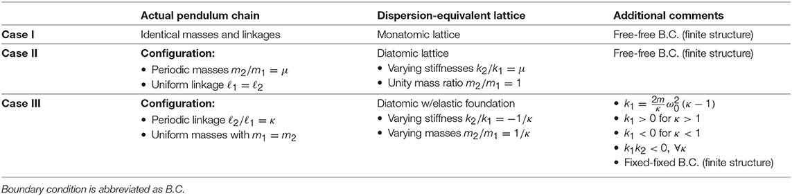
Table 1. A summary of the considered periodic pendulum chain cases and their equivalent PC lattice with the presence of a payload mass.
4. Experimental Validation
To verify the emergence of the aforementioned class of Bragg band gaps in a periodically architected pendulum chain, a full-scale experimental apparatus has been designed and constructed. The experimental setup reflects a periodic arrangement of masses, similar to Case II in section 3.2. The chain, shown in Figure 5A, comprises nineteen masses alternating between heavy (Linkage 1) and light (Linkage 2) linkages with a mass ratio μ = 1/3.46. The linkages were constructed from quarter-inch polycarbonate plates and a set of 3D-printed PLA plastic sections. The lumped-masses consist of one bearing, machine screw fasteners, and –in the case of Linkage 1– brass cylinders to increase the mass. The periodic pendulum chain was suspended from a cart, such that its motion is constrained in one direction and actuated by an electrodynamic shaker. A payload was fixed to the final mass in the chain such that the ratio ϱ is equal to 16.6. A complete to-scale drawing of the experimental apparatus is shown in Figure 5A and the system parameters used in the experiment are summarized in Table 2.
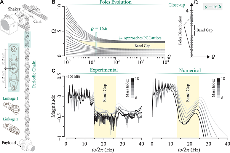
Figure 5. (A) A schematic of the experimental setup comprising a shaker, cart and the pendulum chain with periodic mass (linkage) variations carrying a payload. (B) Evolution of poles as a function of the ratio ϱ and a close-up of pole distribution at ϱ = 16.6 (value used in the experimental testing). (C) Experimental and numerical transfer functions of the even-numbered masses starting at i = 8 with respect to the cart for a frequency sweep up to 40 Hz.
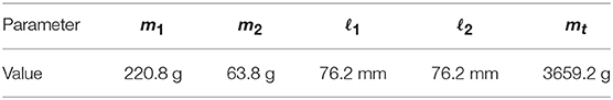
Table 2. A summary of the system parameters used in the experimental setup.
The ratio ϱ = 16.6 used in this experiment is sufficiently large to initiate a band gap in the periodic chain, yet smaller (in width) in comparison to the fully developed band gap at large values of ϱ. As such, the evolution of the system poles as the ratio ϱ approaches infinity is crucial in the experimental design as well as quantifying the anticipated band limits associated with different system parameters. Figure 5B illustrates such evolution by capturing the variation in the distribution of natural frequencies as a function of ϱ. As expected, the finite system approaches the analytical solution in Equation (28) as the payload mass increases. The numerically computed band gap at ϱ = 16.6 is also seen in the close-up shown in Figure 5B.
In order to experimentally capture and measure the band gap, a frequency sweep excitation was carried out and the transfer functions between the cart and various linkages throughout the chain were measured. The electrodynamic shaker was actuated over a range of frequencies ranging from 1 to 40 Hz via a signal generator and an accompanying amplifier system. Two piezoelectric accelerometers were fixed to the chain, one attached to the cart and the second to the even-numbered masses, starting at the eighth mass up to the chain's end. The results of the experimental frequency response are given in Figure 5C. The left plot of Figure 5C shows the magnitude of the experimentally obtained transfer function as a function of frequency, whereas the right plot shows simulation results for the system described in section 3.2 (Case II), albeit with a moderate degree of damping. The experimental results agree reasonably well with the numerical simulations. Specifically, the emergent band gap approximately spans the ranges 14.7–26.5 Hz and 13.1–24.5 Hz in the experimental and numerical cases, respectively.
Finally, a visualization of the band gap is obtained via a video recording of the chain's response in real time. Figure 6A shows a front view of the fully assembled setup, as well as close-ups of its top mount (i.e., shaker and cart system) and the different linkages. A set of reflective markers were attached to the center of the lumped masses to capture the spatial wave profiles under different excitation frequencies. A concentrated light beam is shined on the reflective markers with the surrounding space being dimmed to clearly reflect the oscillations of the chain, and the response of the chain is tracked in slow motion via a fixed camera facing the setup. Snapshots of the recordings are shown in Figure 6B for 3.3, 9.6, and 16 Hz excitations. The first two cases represent a couple of vibration modes where the injected wave propagates freely to the payload at the bottom end of the chain. The last case, i.e., 16 Hz, corresponds to a band gap frequency and the blocked wave propagation can be clearly observed. For completeness, a video demonstration of the entire experiment is attached as a multimedia file in the Supplementary Material.
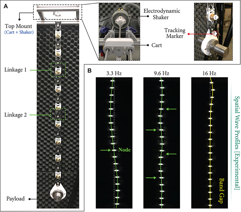
Figure 6. (A) Front view of the fully assembled pendulum chain (left). Close-ups of the mounting system, electrodynamic shaker, cart as well as the linkages with the attached reflective markers (right). (B) Experimental snapshots of the spatial wave profiles outside (3.3 and 9.6 Hz) and inside (16 Hz) a band gap.
5. Concluding Remarks
In this paper, the ability of a passive and non-dissipative periodic pendulum chain to exhibit self-induced vibration isolation capabilities was demonstrated. Given the non-trivial and coupled nature of the pendulum chain dynamics, an obvious definition of a unit cell –typically needed to conduct and predict Bragg band gaps in self-repeating structures– does not exist. Instead, a pseudo unit cell of an equivalent PC lattice was identified and extracted from the finite chain's response in a novel and innovative manner. The analysis showed that the payload carried by the pendulum chain becomes key to the formation of the equivalent PC system and, in its presence, the system shows a similar dispersive behavior. As a result, periodic variations in the pendulums masses or links (with a tip mass) create a frequency band gap which has been verified in both frequency and time domains. As a very intriguing observation, we showed that: (1) The variation in masses resembles the effect of varying the stiffness in a conventional PC. (2) On the other hand, a periodic change in the connecting links becomes reminiscent of a PC lattice with a periodic elastic foundation as well as a periodic variation in the masses. Both cases, however, act identically since the hypothetical elastic foundation comprises a negative stiffness which nullifies its own effect. This is particularly interesting given that negative stiffness systems are typically the product of auxetic structures or actively controlled elements, as opposed to the current case where it emerges solely from the pendulum's unique arrangement. The unconventional dynamics of the pendulum chain have been experimentally demonstrated via transfer function measurements, showing a clear evidence of the predicted band gaps, in addition to snapshots of the spatial profiles both inside and outside the band gap which support the derived transfer function. The potential of the proposed pendulum chains can extend beyond industrial crane applications to ones which involve vibration control of payload deliveries including, but not limited to, robotic arms (O'Connor, 2007), descending payloads of unmanned aerial vehicles (Goodarzi et al., 2015) as well as tethered space elevators (Kim and Vadali, 1995; Williams, 2009).
Author Contributions
HA conceived the idea and conducted the derivations and simulations. JC and HA carried out the experimental work. HA and MN prepared the analysis, figures and discussion. MN prepared the supplementary material. All authors co-wrote the paper.
Funding
The authors acknowledge the support of this work from the US National Science Foundation through awards no. 1647744 and 1847254 (CAREER).
Conflict of Interest Statement
The authors declare that the research was conducted in the absence of any commercial or financial relationships that could be construed as a potential conflict of interest.
Supplementary Material
The Supplementary Material for this article can be found online at: https://www.frontiersin.org/articles/10.3389/fmats.2019.00119/full#supplementary-material
Supplementary Video 1. Experimental demonstration of a phononic band gap in a periodically architected pendulum carrying an end payload. Spatial wave profiles are shown at 3.3 Hz. 9.6 and 16 Hz (band gap) in both real-time speed and slow motion. Testing was carried out in the Sound and Vibrations Laboratory (SVL) at the University at Buffalo.
References
Abdel-Rahman, E. M., Nayfeh, A. H., and Masoud, Z. N. (2003). Dynamics and control of cranes: a review. Modal Anal. 9, 863–908. doi: 10.1177/1077546303009007007
Airoldi, L., and Ruzzene, M. (2011). Design of tunable acoustic metamaterials through periodic arrays of resonant shunted piezos. New J. Phys. 13:113010. doi: 10.1088/1367-2630/13/11/113010
Al Ba'ba'a, H., Nouh, M., and Singh, T. (2017). Pole distribution in finite phononic crystals: understanding bragg-effects through closed-form system dynamics. J. Acoust. Soc. Am. 142, 1399–1412. doi: 10.1121/1.5001513
Al Ba'ba'a, H. B., Callanan, J., Nouh, M., and Singh, T. (2018). Band gap synthesis in elastic monatomic lattices via input shaping. Meccanica 53, 3105–3122. doi: 10.1007/s11012-018-0865-8
Bacquet, C. L., Al Ba'ba'a, H., Frazier, M. J., Nouh, M., and Hussein, M. I. (2018). “Chapter 2: Metadamping: dissipation emergence in elastic metamaterials,” in Advances in Applied Mechanics, Vol. 51. doi: 10.1016/bs.aams.2018.09.001
Bilal, O. R., and Hussein, M. I. (2011). Ultrawide phononic band gap for combined in-plane and out-of-plane waves. Phys. Rev. E 84:065701. doi: 10.1103/PhysRevE.84.065701
Celli, P., and Gonella, S. (2015). Tunable directivity in metamaterials with reconfigurable cell symmetry. Appl. Phys. Lett. 106:091905. doi: 10.1063/1.4914011
Chen, Y., Huang, G., and Sun, C. (2014). Band gap control in an active elastic metamaterial with negative capacitance piezoelectric shunting. J. Vibrat. Acoust. 136:061008. doi: 10.1115/1.4028378
da Fonseca, C. (2007). On the eigenvalues of some tridiagonal matrices. J. Comput. Appl. Math. 200, 283–286. doi: 10.1016/j.cam.2005.08.047
da Fonseca, C., and Petronilho, J. (2001). Explicit inverses of some tridiagonal matrices. Linear Algebra Appl. 325, 7–21. doi: 10.1016/S0024-3795(00)00289-5
Geniet, F., and Leon, J. (2002). Energy transmission in the forbidden band gap of a nonlinear chain. Phys. Rev. Lett. 89:134102. doi: 10.1103/PhysRevLett.89.134102
Giorgio, I., and Del Vescovo, D. (2018). Non-linear lumped-parameter modeling of planar multi-link manipulators with highly flexible arms. Robotics 7:60. doi: 10.3390/robotics7040060
Goodarzi, F. A., Lee, D., and Lee, T. (2015). Geometric control of a quadrotor uav transporting a payload connected via flexible cable. Int. J. Cont. Automat. Syst. 13, 1486–1498. doi: 10.1007/s12555-014-0304-0
Huang, H. H., Sun, C. T., and Huang, G. L. (2009). On the negative effective mass density in acoustic metamaterials. Int. J. Eng. Sci. 47, 610–617. doi: 10.1016/j.ijengsci.2008.12.007
Hussein, M. I., Leamy, M. J., and Ruzzene, M. (2014). Dynamics of phononic materials and structures: historical origins, recent progress, and future outlook. Appl. Mech. Rev. 66:040802. doi: 10.1115/1.4026911
Jallouli, A., Kacem, N., and Bouhaddi, N. (2017). Stabilization of solitons in coupled nonlinear pendulums with simultaneous external and parametric excitations. Commun. Nonlin. Sci. Numer. Simulat. 42, 1–11. doi: 10.1016/j.cnsns.2016.05.012
Kim, E., and Vadali, S. R. (1995). Modeling issues related to retrieval of flexible tethered satellite systems. J. Guid. Cont. Dyn. 18, 1169–1176. doi: 10.2514/3.21521
Li, J., and Chan, C. T. (2004). Double-negative acoustic metamaterial. Phys. Rev. E 70:055602. doi: 10.1103/PhysRevE.70.055602
Liu, L., and Hussein, M. I. (2012). Wave motion in periodic flexural beams and characterization of the transition between bragg scattering and local resonance. J. Appl. Mech. Trans. ASME 79:011003. doi: 10.1115/1.4004592
Masoud, Z. N., and Alhazza, K. A. (2017). A smooth multimode waveform command shaping control with selectable command length. J. Sound Vibrat. 397, 1–16. doi: 10.1016/j.jsv.2017.02.049
Masoud, Z. N., and Nayfeh, A. H. (2003). Sway reduction on container cranes using delayed feedback controller. Nonlin. Dyn. 34, 347–358. doi: 10.1023/B:NODY.0000013512.43841.55
Miu, D. (1993). Mechatronics: Electromechanics and Contromechanics (Book). New York, NY: Springer. doi: 10.1007/978-1-4612-4358-8
O'Connor, W. J. (2007). Wave-based analysis and control of lump-modeled flexible robots. IEEE Trans. Robot. 23, 342–352. doi: 10.1109/TRO.2007.895061
Pai, P. F., Peng, H., and Jiang, S. (2014). Acoustic metamaterial beams based on multi-frequency vibration absorbers. Int. J. Mech. Sci. 79, 195–205. doi: 10.1016/j.ijmecsci.2013.12.013
Pal, R. K., Vila, J., Leamy, M., and Ruzzene, M. (2018). Amplitude-dependent topological edge states in nonlinear phononic lattices. Phys. Rev. E 97:032209. doi: 10.1103/PhysRevE.97.032209
Russell, F., Zolotaryuk, Y., Eilbeck, J., and Dauxois, T. (1997). Moving breathers in a chain of magnetic pendulums. Phys. Rev. B 55:6304. doi: 10.1103/PhysRevB.55.6304
Ruzzene, M., and Baz, A. (2000). Control of wave propagation in periodic composite rods using shape memory inserts. J. Vibrat. Acoust. 122, 151–159. doi: 10.1115/1.568452
Süsstrunk, R., and Huber, S. D. (2015). Observation of phononic helical edge states in a mechanical topological insulator. Science 349, 47–50. doi: 10.1126/science.aab0239
Trainiti, G., and Ruzzene, M. (2016). Non-reciprocal elastic wave propagation in spatiotemporal periodic structures. New J. Phys. 18:083047. doi: 10.1088/1367-2630/18/8/083047
Williams, P. (2009). Dynamic multibody modeling for tethered space elevators. Acta Astronaut. 65, 399–422. doi: 10.1016/j.actaastro.2008.11.016
Appendix
1. Dispersion of Pendulums With Periodic Masses
The unit cell equations of motion corresponding to the system shown in Figure 3B in the manuscript can be written as
where ui and vi represent the displacement of the odd and even numbered masses, respectively. Applying the Bloch-wave solution and assuming harmonic motion result in an eigenvalue problem, the determinant of which yields the dispersion relation:
For the case of and k2 = μk1 and dividing by m2 throughout yields
Normalizing Equation (37) using ω0, we obtain the nondimensional dispersion relation in Equation (26) in the manuscript.
2. Dispersion of Pendulums With Periodic Links
For the unit cell marked in Figure 4B in the manuscript, the equations of motion can be written as
where ui and vi are as defined in Appendix 1. The dispersion relation can be derived as
Given the matrix definition in Equation (30) in the manuscript, (2k + k1) is equal to based on the odd numbered diagonal elements of the matrix. Knowing that from the off-diagonal elements, we solve for k1 which gives k1 = 2k(κ − 1). Similarly, (2k + k2) is equal to based on the even numbered diagonal elements, which results in when solving for k2. The inverse of the matrix K in Equation (31) in the manuscript can be treated as the equivalent mass matrix of the PC lattice which gives m1 = m and . Substituting the values of m1, m2, k1 and k2 and dividing by , the dispersion relation reduces to
Upon normalization, we obtain the dispersion relation in Equation (32) in the manuscript. It is noticed here that the terms k1k2 and 2k(k1 + k2) in Equation (40), which are essential for creating a zero frequency band gap, cancel out each other for the given values of k1 and k2. It is also observed that the final form of Equation (41) is very similar to Equation (37) even though the equations of motion for the finite structures are completely different.
Keywords: pendulums, phononic, wave dispersion, band gap, finite structures
Citation: Al Ba'ba'a H, Callanan J and Nouh M (2019) Emergence of Pseudo-Phononic Gaps in Periodically Architected Pendulums. Front. Mater. 6:119. doi: 10.3389/fmats.2019.00119
Received: 09 February 2019; Accepted: 08 May 2019;
Published: 06 June 2019.
Edited by:
Federico Bosia, University of Turin, ItalyReviewed by:
Vincent Laude, UMR6174 Institut Franche Comté Électronique Mécanique Thermique et Optique Sciences et Technologies (FEMTO-ST), FranceYue-Sheng Wang, Tianjin University, China
Copyright © 2019 Al Ba'ba'a, Callanan and Nouh. This is an open-access article distributed under the terms of the Creative Commons Attribution License (CC BY). The use, distribution or reproduction in other forums is permitted, provided the original author(s) and the copyright owner(s) are credited and that the original publication in this journal is cited, in accordance with accepted academic practice. No use, distribution or reproduction is permitted which does not comply with these terms.
*Correspondence: Mostafa Nouh, bW5vdWhAYnVmZmFsby5lZHU=