 Yan-Li Shi
 Long Zheng
 Wen-Da Wang
- School of Civil Engineering, Lanzhou University of Technology, Lanzhou, China
In this study, a finite element (FE) analysis of a composite joint with the concrete-filled steel tubular (CFST) column and steel beam, with a through bolt-extended endplate, was carried out in a progressive collapse. The reasonable constitutive model of a steel plate, through bolt and core concrete materials under a large deformation were selected, and the comprehensive fracture criterion and damage evolution path of the ductile damage, shear damage and mixed damage modes based on the stress triaxiality, were considered in the steel constitutive structure, respectively. The accuracy of the modeling method and material constitutive, was verified by a comparison of the overall deformation processes, failure modes and resistances of joints, with both experimental and FE results. A typical composite joint, with the CFST column and steel beam with through bolt-extended endplate was designed, and four joints were derived for comparison by adjusting the diameter of the through bolt and the thickness of the extended endplate. The FE models of these five joints were established to investigate failure modes and resistance mechanisms by using the ABAQUS/Explicit module. The results showed that the failure modes of the composite joint with the CFST column and steel beam with through bolt-extended endplate, can be divided into three types: steel beam and through bolts failure, through bolts failure, and steel beam failure. The different strengths and weaknesses between the through bolt, extended endplate and steel beam affect the progressive collapse resistance of the joint directly. With the increase of the diameter of the through bolt and the thickness of the extended endplate, the failure mode of the joint gradually turns from through bolt failure to steel beam failure, and the resistance and ductility of the joint are enhanced and the anti-progressive collapse ability of the composite joint, with a CFST column and steel beam with a through bolt-extended endplate, increases.
Introduction
Progressive collapse is the collapse or the disproportionate damage from the initial damage of a structure. Since the incident of Ronan Point apartment in 1958, progressive collapse captured the public's attention. After the incident of the World Trade Center buildings in 2001, studies on progressive collapse entered a climax (Adam et al., 2018). Yi et al. (2008) conducted an experimental study on progressive collapse resistance of a four-bay and three-story reinforced concrete frame and analyzed the resistance mechanism. Dinu et al. (2016) carried out a test on a 2 × 2 bay one-story steel frame under column loss, and the beam to column connection type was a bolt-extended endplate. The influence of the main and secondary beam connection was considered in the test in general. Pirmoz and Liu (2016) carried out an experimental and FE study on a three-story double-span steel frame against a progressive collapse, which uses a post-tensioned beam to column connection. Li et al. (2017) conducted a static test on the 3D reduced scale steel frame under inter column loss and analyzed the torsion effect of the main and secondary beam connection mainly. Wang et al. (2017) established FE models of CFST column to steel beam frame, using multi-scale modeling under static and dynamic loads.
As the preliminary resistance of a structural defense against a progressive collapse, the joint plays an important role in the frame structure. Recently, many researchers have carried out large-scale studies on the progressive collapse resistance of the joint. Sadek et al. (2011) conducted a comparison test of ordinary steel connections, reduced beam steel connections and ordinary concrete connections against a progressive collapse. Yang and Tan (2013) carried out static loading tests on steel beam to column joints with simple connections and semi-rigid connections and investigated the failure modes of joints with different bolt configurations. Oosterhof and Driver (2015) conducted a study on the shear beam to column connections under column removal. Wang et al. (2016) carried out an experimental and FE study on the anti-progressive collapse of three types of steel tube column to steel beam substructures. Guo et al. (2013) and Guo et al. (2015) conducted tests on the steel-concrete composite frames with rigid and semi-rigid connections, respectively. And Guo et al. (2014) and Gao et al. (2017) conducted experimental studies on the sagging moment, hogging moment, and tensile force of these two types of composite joints. Gong (2017) conducted an experimental study on the bolted-angle connections against progressive collapse, and the test results included the deformation and resistance curves of specimens. Dinu et al. (2017) conducted an anti-progressive collapse test on four specimens with a three-column double-span substructure and discussed the influence of rigid and semi-rigid connections. Xu et al. (2018a) conducted an experimental study about the resistance of a CFST column to steel beam with different bolted configurations, and the connection types covered the flush end-plate, extended the end-plate and stiffened the angle. Wang et al. (2018) performed an FE analysis of a CFST column to steel beam with a through-center construct against a progressive collapse. The characteristics, advantages, and disadvantages of the failure mode at the beam and at the column were analyzed, respectively. However, the above-mentioned research mainly focuses on steel structures and reinforced concrete structures, while there are few studies on composite structures such as CFST structures. In addition, there are few studies on the connections of through bolt-extended endplate, so it is necessary to carry out the resistance of a progressive collapse of the composite joint with the CFST column and steel beam with through bolt-extended endplate.
Indeed, the study of progressive collapse involves the fracture of metallic materials under a large deformation, including the fracture criterion and damage evolution path. Early scholars judged the damage criterion of steel based on the principle of micro-holes and micro-cracks inside the metal (McClintock, 1968; Roy et al., 1981; Atkins, 1996), and then scholars began to pay attention to the decisive influence of stress triaxiality on the damage criterion of steel (Rice and Tracey, 1969; Hancock and Mackenzie, 1976; Mirza et al., 1996; Rosa et al., 2001; Bao and Wierzbicki, 2004). The widely used fracture criterion includes VGM criterion, SMCS criterion and X-W criterion. Rice and Tracey (1969) proposed the VGM criterion, that is, the degradation mechanism of nucleation, expansion, aggregation and shrinkage of the hole. When the material stress and strain history integral amount reaches a certain value, the material is judged as damaged. Hancock and Mackenzie (1976) proposed the SMCS criterion, which instead of considering the integral form of stress triaxiality to plastic strain, assumes that the stress triaxiality remains unchanged in the damage process. Wierzbicki and Xue (2005) and Xue (2005) proposed the X-W criterion, which is mainly based on the equivalent plastic strain accumulation mechanism, that is, when the internal equivalent plastic strain accumulation reaches the critical value, the materials begin to enter the damage state. Xu and Wu (2012) and Xu et al. (2013, 2018b, 2019) carried out damage detection studies of structures and bridges based on different damage criterion and evolution processes. Indeed, the damage evaluation criterion and evolution process of steel at the degradation stage are relatively complex, moreover, the fracture criterion and damage evolution path of materials are key issues in the study of joint anti-progressive collapse. However, previous scholars did not pay much attention to these two issues, which should be considered in detail.
In this paper, the reasonable steel constitutive model was selected, and the comprehensive fracture criterion and within this model, the damage evolution path based on stress triaxiality was considered. The results of relevant tests were selected to simulate and verify the accuracy of the modeling method and material constitutive. One typical composite joint with a CFST column and steel beam with a through bolt-extended endplate named SJ-EP-TB-1 was designed, and four joints were derived for comparison, by adjusting the diameter of the through bolt and the thickness of the extended endplate. The FE models of these five joints were established to investigate the failure modes and resistance mechanisms, using the ABAQUS/Explicit module.
Materials Constitutive Models
This paper involves the CFST column and the stress of this type of concrete is more complicated than ordinary concrete. Due to the interaction between the steel tube and core concrete, the restraint of the steel tube on concrete, should be considered. This paper refers to the constitutive model of the compressive state of core concrete with a square section, considering the constraint effect of the steel tube proposed by Han et al. (2007).
where, x = , y = = ,
In which, ε and ε0 is the concrete compressive strain and peak compressive strain, respectively. σ and σ0 is the concrete compressive stress and peak compressive stress, respectively. The units for stress and strain are N/mm2 and με, respectively. is the cylinder strength of concrete. ξ is the confinement factor, and is defined as following:
Where, AS and AC is the cross-sectional areas of the steel and concrete, respectively. fy is the yield strength of steel and fck is the characteristic strength of the concrete.
In addition, the ABAQUS/Explicit module is used to analyze the progressive collapse performance of the substructure, which involves the tension and compression yield, plastic deformation and damage evolution of low-alloy steel materials. The reasonable constitutive models of steel plate and through bolt under large deformation should to be reconsidered in this paper. The comprehensive fracture criterion and damage evolution path of metal ductile damage, shear damage, and mixed damage modes based on stress triaxiality are considered in the steel constitutive structure.
The constitutive model before the degradation of steel is based on the steel plate or reinforcement model proposed by Esmaeily and Xiao (2005), which is considered as the stress and strain relationship between the elastic stage, the yield platform stage, and the strengthening stage simply. By controlling k1, k2, k3, the shape at the yield platform stage and the strengthening stage in the uniaxial tensile stress-strain curve are adjusted (see Figure 1). The simplified stress-strain relationship is as shown in Equation (3). In the FE model of this paper, low-alloy steel plates are used for the steel beam, steel tube and extended endplate, the values are set as k1 = 3, k2 = 300, and k3 = 1.4. And the 10.9S high strength bolts are used for through bolts, with the values set as k1 = 3, k2 = 60, and k3 = 1.3.
Where,
Es is the elastic modulus of steel,
f y is the yield strength of steel,
εy is the yield strain of steel,
k1 is the ratio of the starting strain of the strengthening stage to the yield strain,
k2 is the ratio of the peak strain to the yield strain,
k3 is the ratio of the peak stress to the yield strength.
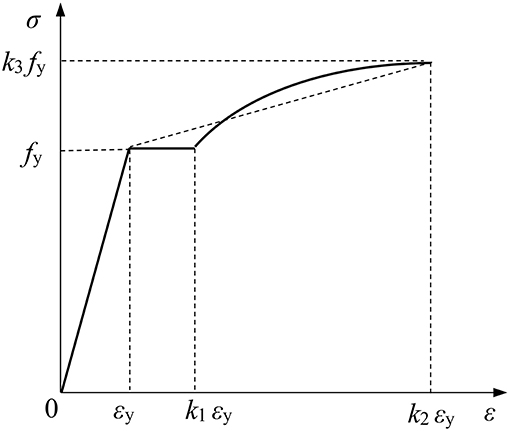
Figure 1. The constitutive model before the degradation of steel.
According to the relevant test data of low-alloy steel in the real tensile condition (Chen et al., 2015, 2016, 2017), the stress-strain curve of steel at the strength degradation stage does not satisfy the shape characteristics of the second-order parabola, so the constitutive relationship of the fracture degradation stage of steel does not adopt the steel model proposed by Esmaeily and Xiao (2005). Moreover, the damage criterion and evolution process of steel at the degradation stage are relatively complex. Based on the X-W fracture criterion proposed by Wierzbicki and Xue (2005) and Xue (2005), the simplified equivalent plastic strain formula under the influence of stress triaxiality is proposed with reference to Yu and Jeong (2010) and Zhou et al. (2014):
Where,
η0 is 0.33,
C1 is the critical plastic damage strain under pure shear condition,
C2 is the critical plastic damage strain under uniaxial tension condition, which can be determined by the area reduction rate (AR) after the material test is interrupted.
The conversion relationship between C1 and C2 can be determined by the following equations:
Where K and n are steel hardening parameters which can be derived from the true stress-strain curve, respectively.
Figure 2 shows the relationship between the stress triaxiality and critical equivalent plastic strain. It can be seen from the figure that the damage state can be judged by the value of stress triaxiality: shear damage (−1/3 < η ≤ 0), mixed damage (0 < η ≤ η0), ductile damage (η0 < η). The comprehensive fracture criterion for steel used in this paper is to simulate the damage of steel by inputting the relevant parameters of shear and ductile damage standard in the ABAQUS material module. The relevant parameters include the critical equivalent plastic strain, stress triaxiality, and strain rate. The critical equivalent plastic strain and stress triaxiality are mainly determined by Equation (4). Since the influence of the loading rate is not considered in the model, the strain rate is consistent with the loading rate of the FE model. In other words, this comprehensive fracture criterion covers the critical equivalent plastic strain of different damage modes of steel at the same strain rate.
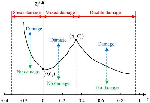
Figure 2. The comprehensive fracture criterion of steel based on stress triaxiality.
Figure 3 shows the damage evolution path of steel. As shown by the red line in the figure, when the true strain reaches the critical equivalent plastic strain (), the steel begins to enter the damage mode. The falling section of the curve is the damage evolution path of steel and the true strain is between the critical equivalent plastic strain () and the fracture strain (). In the case of progressive collapse, the steel beam or through bolt may become damaged. The fracture process may be either a ductile fracture or brittle damage, and the partial fracture process will have a great impact on the resistance mechanism of the remaining key components. Therefore, the damage evolution path in the material constitutive is crucial.
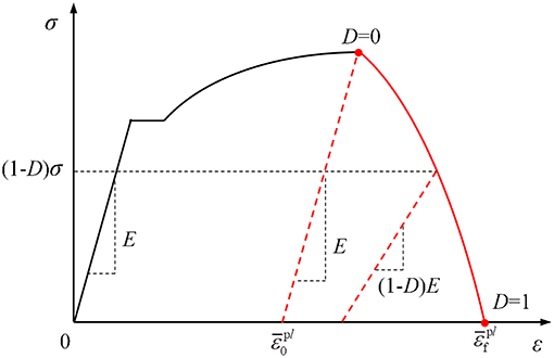
Figure 3. The damage evolution path of steel.
The damage evolution path of steel can be controlled by the damage factor (D). When D = 0, the material does not damage. And when D = 1, the material completely fails. As shown in Figure 3, the residual modulus and residual stress can express the steel degradation process curve:
Where,
E is the elastic modulus,
σ is the stress at the elastic stage,
Ē is the residual modulus at the degradation stage,
is the residual stress at the degradation stage,
D is the damage parameter.
The ABAQUS/Explicit module provides two methods to define the damage evolution path, one is based on the fracture displacement and the other is based on the energy. In this paper, the linear displacement method is adopted, that is, the damage path evolution is realized by defining the damage displacement () at D = 1. In order to reduce the influence of damage evolution on FE mesh size and quality, the plastic displacement () is defined as follows:
Where Le is the characteristic length of the FE mesh, which is defined by ABAQUS as the square root of the integral point area of the shell element and the cube root of the integral point volume of the solid element (Dassault Systemes Simulia Corp., 2014; ABAQUS Analysis User's Manual Version 6.14).
When the material plastic displacement () of one element reaches the material fracture displacement (), the ABAQUS/Explicit module can delete the element automatically. The material fracture displacement () can be measured by a uniaxial tensile material test:
Where el and dl are the elongation and gauge length measured by the uniaxial tensile property test, respectively.
Fe Method
The ABAQUS/Explicit module is used to analyze the resistance to progressive collapse of the composite joint with the CFST column and steel beam with through bolt-extended endplate. The rationality of this modeling method is verified by comparing the relevant static tests. Instances of one FE model include: loading plate, steel tube, core concrete, H-shaped steel beams, through bolts, extended endplates, and all of them use a C3D8R solid element. The loading plate is connected with the top of the CFST column and the steel beams on both sides are connected with the extended endplates, and the connection modes of theses use a “tie” interaction. In addition, the core concrete and the inner wall of the steel tube are set to “surface to surface” contact, with a friction penalty of 0.25. The bolt holes are reserved for the extended endplates and the steel tube, since that should be passed through by the through bolts. And the remaining contact faces are defined as “general contact” with a friction penalty of 0.45. The steel beam sections at both ends are coupled to two reference points, which are defined as hinged supports. The vertical load controlled by displacement is applied to the loading plate. Considering the influence of the loading rate on the kinetic energy of the model and the inertia of the joint in the ABAQUS/Explicit module, the smoothing loading curve is applied to the loading process. In order to ensure the reasonable development of the fracture effect in the model, the through bolts and the section of steel beam which may fracture is treated with mesh refinement, respectively (see Figure 4).
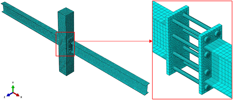
Figure 4. Mesh refinement.
Fe Model Verification
Yang and Tan (2013) carried out a test on the progressive collapse resistance of four simple connections and three semi-rigid connections. In this paper, Specimen 6 was selected for FE verification. The connection type was a high strength bolt-extended end plate. UB 254 × 146 × 37 S355 was selected for the steel beam, UC 203 × 203 × 71 S355 for the steel column, Grade 8.8 M20 steel for the high-strength bolt, and JR 436 × 200 × 12 S275 for the extended end plate, respectively. In order to obtain better simulation results, the FE model of Specimen 6 adopted the C3D8R solid element as shown in Figure 5A. In addition, in the FE model, the weld between the steel beam and extended end plate was weakened according to the test (Yang and Tan, 2013). During the test, the load (P) was applied to the top of column and the displacement of column (Δ) was recorded.
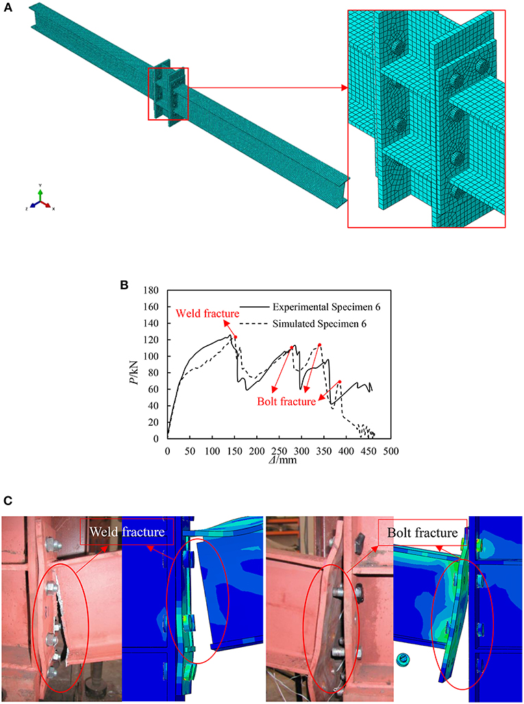
Figure 5. Comparison of simulated and experimental Specimen 6. (A) FE model of Specimen 6. (B) Load-displacement at the top of column curve comparison. (C) Failure mode comparison.
It can be seen from Figure 5B that the FE load-displacement at the top of the column curve deviates from the experimental results slightly. In the early stage of loading, the FE curve stiffness agreed well with the test curve. However, the FE model bearing capacity was slightly lower than Specimen 6 in the test at the elastic-plastic stage. When the test was loaded to 140.68 mm, Specimen 6 was damaged at the weld between the right beam and the extended end plate, and its bearing capacity reached 125.79 kN. When the fracture of weld at the right side occurs in the FE model, the bearing capacity of the joint is 122.31 kN at the displacement of 150.76 mm, which only differs by 2.77% from the experimental value. In the test, the left bolts fractured from the bottom to the top at the displacement of 284.72, 360.37, and 452.07 mm, respectively. When the bolts fractured, the bearing capacity of Specimen 6 reached 113.22, 95.36, and 67.77 kN, respectively. It is worth mentioning that the FE model also simulates the fracture of bolts three times at the displacement of 278.97, 339.62, and 384.76 mm, respectively. In addition, the bearing capacity at the fracture of bolts reached 110.64, 14.84, and 70.16 kN, respectively. It is not difficult to see that there is little difference between the simulation results and test results of the fracturing of bolts.
Figure 5C provides the failure mode comparison of the simulated and experimental Specimen 6. It was observed that by considering the fracturing properties of materials, the FE model can more accurately simulate the fracture at the weld and bolt, while the time and mode of failure do not differ much from the test results.
Dinu et al. (2017) conducted a progressive collapse test on four single-layer steel frames. In this paper, Specimen EP was selected for FE verification. The connections type was bolt-extended end plate. HEB 260 × 160 × 10 × 17.5 S275 was selected for the steel beam of this specimen, IPE 220 × 110 × 5.9 × 9.2 S275 for the steel column, and Grade 10.9S M16 for the high-strength bolt. In order to obtain better simulation results, the FE model of Specimen EP adopted the C3D8R solid element as shown in Figure 6A. During the test, the load (P) was applied to the top of the middle column and the displacement of the middle column (Δ) was recorded.
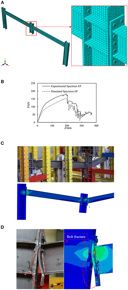
Figure 6. Comparison of simulated and experimental Specimen EP. (A) FE model of Specimen EP. (B) Load-displacement at the top of middle column curve comparison. (C) Overall deformation comparison. (D) Failure mode comparison.
Figure 6B provides the load-displacement at the top of the middle column curve comparison of the simulated and experimental Specimen EP. The comparative result shows a good agreement between the simulated and experimental curves of Specimen EP in general. In the elastic stage, the simulated curve stiffness is slightly lower than the test curve. When the test was loaded to 195.66 mm, Specimen EP was damaged. While the failure displacement of the FE model is 192.96 mm, the difference between them is only 1.38%. Meanwhile, the ultimate bearing capacity of Specimen EP in test was 181.85 kN, which was 154.94 kN in the FE model. When Specimen EP entered the failure stage, the bolts were destroyed in sequence. However, the bearing capacity curve rose briefly and continued to oscillate since the structure did not completely lose the bearing capacity after parts of bolts fractured. The FE model achieves the above phenomenon completely and agrees well with the experimental results.
Figure 6C provides the overall deformation comparison of the simulated and the experimental Specimen EP. When the middle column had a large vertical displacement, the steel beam on both sides rotated around the rotating center. However, the asymmetric deformation of the joint occurred in the test. The failure of bolts occurred on one side first and then the fracture spread in this side gradually, while the other side of the joint did not damage. The FE method adopted in this paper can simulate the deformation mode accurately by considering the fracture property parameters.
Figure 6D provides the failure mode comparison of the simulated and experimental Specimen EP. During the test, the bolts on the right side of the middle column fractured when the displacement reached 195.66, 234.66, and 267.87 mm, respectively. In the FE model, the failure sequence of the bolt group and the deformation mode of the extended end plate are consistent with the test results. And the displacement of the simulated Specimen EP is similar to the test results at the bolts that are fractured. When the displacement reached 365.34 mm at the end of the test, the lower 6 bolts on the right side were damaged and the upper 4 were not damaged. The FE results are completely consistent with the experimental results.
Gao et al. (2017) conducted an experimental study on the sagging moment, hogging moment and tensile force of semi-rigid composite joints, respectively. In this paper, Specimen SJS was selected for FE verification. The connections type was a bolt- flush end plate. HN 200 × 100 × 5.5 × 8 was selected for the steel beam of this specimen, HW200 × 200 × 8 × 12 for the steel column, and Grade 10.9S M16 for the high-strength bolt. In order to obtain better simulation results, the FE model of Specimen SJS adopted the C3D8R solid element as shown in Figure 7A. During the test, the load was applied to the top of column and the displacement of column (Δ) was recorded. The calculation method of the bending moment (M) and rotation angle (θ) are referred to in Gao et al. (2017).
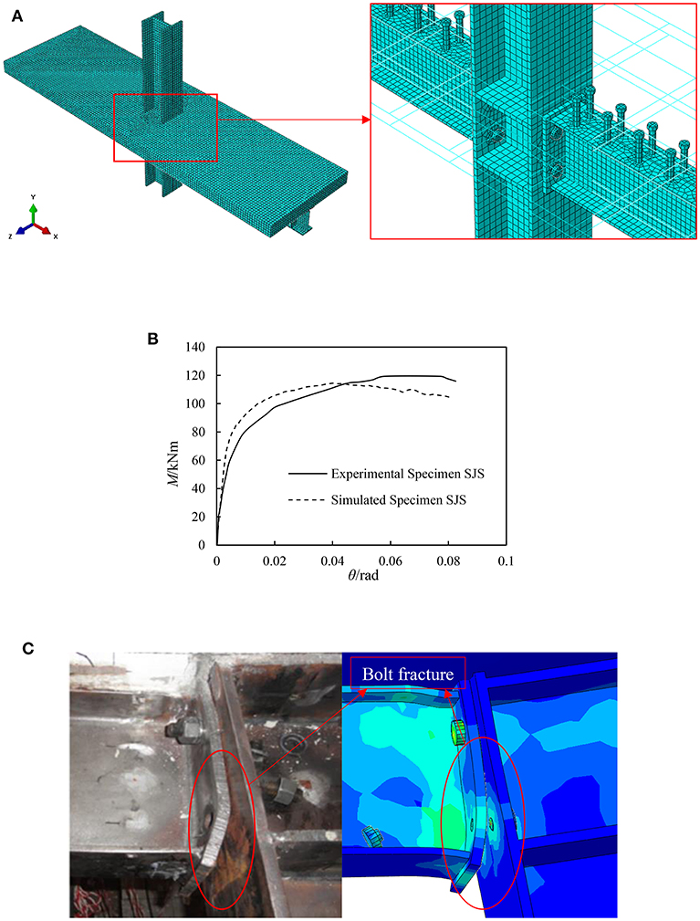
Figure 7. Comparison of simulated and experimental Specimen SJS. (A) FE model of Specimen SJS. (B) Bending moment-rotation angle curve comparison. (C) Failure mode comparison.
Figure 7B provides the bending moment-rotation angle curve comparison of the simulated and experimental Specimen SJS. The comparative result shows a good agreement between the simulated and experimental curves of Specimen SJS. In the elastic stage, the simulated curve stiffness is slightly higher than the experimental curve, and the simulated curve enters the elastoplastic stage later than the experimental curve. In the plastic stage, the simulated curve shows a slight downward trend, which is not reflected in the test curve. When the rotation angle of Specimen SJS was loaded to 0.82 in the test, the bending moment was 115.89 kNm. In addition, the bending moment was 104.10 kNm at the rotation angle of the simulated Specimen SJS is 0.82.
Figure 7C provides the failure mode comparison of the simulated and the experimental Specimen SJS. In the test, the lower bolts on both sides of the middle column fractured, which was realized perfectly in the FE model. Meanwhile, the flush end plates on both sides showed obvious bending phenomenon in the test, and the bending of the flush end plates of simulated Specimen SJS is similar to the test results. In brief, the FE results are completely consistent with experimental results.
Joints Model Design
A typical composite joint with the CFST column and steel beam with through bolt-extended endplate was designed, named SJ-EP-TB-1, whose predictable fractured component would be the steel beam and the through bolts. On the basis of typical joint SJ-EP-TB-1, it was proposed to control different predictable fractured components by adjusting the diameter of the through bolt and the thickness of the extended endplate. The joints whose predictable fractured component would be the through bolts, were named SJ-EP-TB-2 (by reducing the diameter of the through bolt) and SJ-EP-TB-4 (by reducing the thickness of the extended endplate), respectively. The joints whose predictable fractured component would be the steel beam, were named SJ-EP-TB-3 (by increasing the diameter of the through bolt) and SJ-EP-TB-5 (by increasing the thickness of the extended endplate), respectively. The section of the CFST column of joints is square, the span of the steel beams is 5600 mm, and the length of the CFST columns is 2000 mm. The parameters of the joints are shown in Table 1. The construction details of joints are shown in Figure 8.
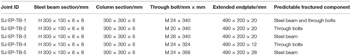
Table 1. Parameters of joints.
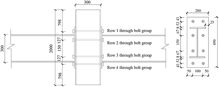
Figure 8. Construction details of joints.
The Influence of Key Component Characteristic
Table 2 provides the results of joints with different diameters of through bolts. Figure 9 provides the resistance curve comparison. According to the comparison results, the diameter of the through bolt had a great influence on the progressive collapse resistance of the composite joint with a CFST column and the steel beam with a through bolt-extended endplate. The failure mode is usually the through bolts failure when the diameter of the through bolt is too small. However, with the increase of the diameter of the through bolt, the possibility of the through bolts fracture is reduced, that is, the failure mode is gradually transformed to the steel beam failure.
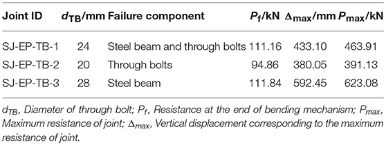
Table 2. Results of joints with different diameter of through bolt.
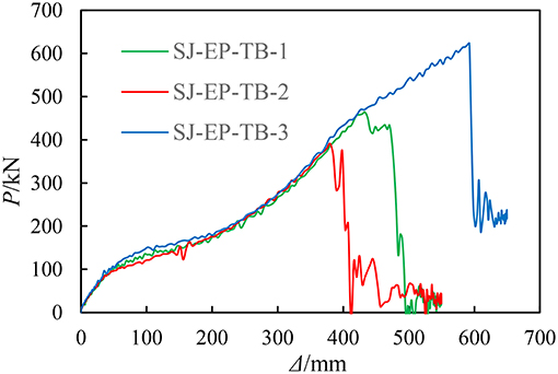
Figure 9. Resistance curves comparison with a different diameter of the through bolt.
Specifically, the bolt diameters of SJ-EP-TB-2, SJ-EP-TB-1, and SJ-EP-TB-3 are 20, 24, and 28 mm, respectively. The diameter of the through bolt of SJ-EP-TB-2 is the smallest among the three, and its failure mode is the through bolts failure. At the end of bending mechanism, the resistance of the column top (Pf) is 94.86 kN. When the ultimate bearing capacity is reached, the displacement (Δmax) is 380.05 mm and the maximum resistance of joint (Pmax) is 391.13 kN. The diameter of the through bolt of SJ-EP-TB-1 is between the other two, and its failure mode is the steel beam and the through bolts failure. The top resistance at the end of the bending mechanism (Pf) is 111.16 kN, which is 17.18% higher than that of SJ-EP-TB-2. When SJ-EP-TB-1 reaches the ultimate bearing capacity, its vertical displacement (Δmax) and maximum resistance (Pmax) are 433.10 mm and 463.91 kN, respectively, which is 13.94 and 18.61% higher than that of SJ-EP-TB-2. The diameter of the through bolt of SJ-EP-TB-3 is the largest among the three, and its failure mode turns to a steel beam failure. The top resistance at the end of bending mechanism (Pf) is 111.84 kN, which is 17.18% higher than that of SJ-EP-TB-2. When SJ-EP-TB-3 reaches the ultimate bearing capacity, the vertical displacement (Δmax) and maximum resistance (Pmax) are 592.45 mm and 623.08 kN, respectively, which is 55.89 and 59.30% higher than that of SJ-EP-TB-2.
It can be seen that with the increase of the diameter of the through bolt, the failure mode of the joint gradually turns from bolt failure to steel beam failure. And the resistance at the bending mechanism, the ultimate bearing capacity and the ductility of the joint is enhanced. In summary, with the increase of the diameter of the through bolt, the anti-progressive collapse ability of the composite joint with a CFST column and steel beam with a through bolt-extended endplate obviously increases.
Table 3 provides the results of the joints with different thicknesses of the extended endplate. Figure 10 provides the resistance curves comparison. According to the comparison results, the thickness of the extended endplate has a certain influence on the progressive collapse resistance of the composite joint with a CFST column and steel beam with a through bolt-extended endplate. The failure mode is usually the through bolts failure when the thickness of the extended endplate is too small. However, with the increase of the extended endplate thickness, the possibility of the through bolt fracture is reduced, that is, the failure mode is gradually transformed to the steel beam failure.
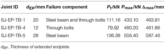
Table 3. Results of joints with different thickness of extended endplate.
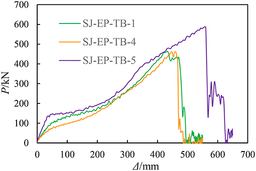
Figure 10. Resistance curves comparison different thickness of extended endplate.
Specifically, the extended endplate thickness of SJ-EP-TB-4, SJ-EP-TB-1, and SJ-EP-TB-5 was 12, 20, and 28 mm, respectively. The thickness of the extended endplate of SJ-EP-TB-4 was the smallest among the three, whose failure mode was the through bolts failure. At the end of the bending mechanism, the resistance of the column top (Pf) was 79.92 kN. When the ultimate bearing capacity is reached, the displacement (Δmax) is 460.20 mm and the maximum resistance of the joint (Pmax) is 461.86 kN. The thickness of the extended endplate of SJ-EP-TB-1 is between the other two, whose failure mode is the steel beam and the through bolts failure. The top resistance at the end of the bending mechanism (Pf) was 111.16 kN, which is 39.09% higher than that of SJ-EP-TB-4. When SJ-EP-TB-1 reaches the ultimate bearing capacity, the vertical displacement (Δmax) is 433.10 mm, which is 5.89% lower than that of SJ-EP-TB-4. And the maximum resistance (Pmax) of SJ-EP-TB-1 is 463.91 kN, which is 0.44% higher than that of SJ-EP-TB-4. The thickness of the extended endplate of SJ-EP-TB-5 is the largest among the three, whose failure mode turns to a steel beam failure. The top resistance at the end of the bending mechanism (Pf) is 136.28 kN, which is 70.52% higher than that of SJ-EP-TB-4. When SJ-EP-TB-5 reaches the ultimate bearing capacity, the vertical displacement (Δmax) and maximum resistance (Pmax) is 556.40 mm and 587.46 kN, respectively, which is 20.90 and 27.19% higher than that of SJ-EP-TB-4.
It can be seen that with the increase of the thickness of the extended endplate, the failure mode of the joint turns from the bolt failure to the steel beam failure gradually. And the resistance and stiffness of the curve at the bending mechanism, the maximum resistance and the ductility of the joint are all enhanced to a certain extent. In summary, with the increase of the thickness of the extended endplate, the resistance to a progressive collapse of the composite joint with a CFST column and steel beam with a through bolt-extended endplate, increases to a certain extent.
Conclusions
In this paper, the reasonable constitutive model of steel plate, through bolt and core concrete was selected. The accuracy of the modeling method and material constitutive was verified by the comparison between the experimental and FE results. One typical composite joint with a CFST column and steel beam with a through bolt-extended endplate named SJ-EP-TB-1 was designed, and four joints were derived for comparison, by adjusting the diameter of the through bolt and the thickness of the extended endplate. The FE models of these five joints were established to investigate failure modes and resistance mechanisms using the ABAQUS/Explicit module. The conclusions may be summarized as follows:
(1) The comprehensive fracture criterion and damage evolution path of metal ductile damage, shear damage, and mixed damage modes, based on stress triaxiality, were considered in the steel constitutive model, which were used as the basis for the study of a large deformation of joints under progressive collapse.
(2) The failure modes of the composite joint with a CFST column and steel beam with a through bolt-extended endplate can be divided into three types: steel beam and through bolts failure, through bolts failure, and steel beam failure, and the different strengths and weaknesses between the through bolt, extended endplate and steel beam affect the progressive collapse resistance of the joint directly.
(3) With the increase of the diameter of the through bolt, the failure mode of the joint gradually turns from bolt failure to steel beam failure, and the resistance at the bending mechanism, the ultimate bearing capacity and the ductility of joint are enhanced. In summary, the anti-progressive collapse ability of the composite joint with a CFST column and steel beam with a through bolt-extended endplate increases obviously.
(4) With the increase of the thickness of the extended endplate, the failure mode of the joint gradually turns from a bolt failure to a steel beam failure, and the resistance and stiffness of the curve at the bending mechanism, the maximum resistance and the ductility of the joint are enhanced to a certain extent. In summary, the resistance to a progressive collapse of the composite joint with a CFST column and steel beam with a through bolt-extended endplate increases to a certain extent.
Author Contributions
Y-LS was responsible for this research. LZ is a Ph.D. student and carried out the research work. W-DW is charge of the whole research subject.
Funding
This research was supported by the National Natural Science Foundation of China (No.: 51778214; 51268038) and the Universities Cooperative Innovation Team of Gansu Province (No.: 2018C-08). The financial support is highly appreciated.
Conflict of Interest Statement
The authors declare that the research was conducted in the absence of any commercial or financial relationships that could be construed as a potential conflict of interest.
References
Adam, J. M., Parisi, F., Sagaseta, J., and Lu, X. Z. (2018). Research and practice on progressive collapse and robustness of building structures in the 21st century. Eng. Struct. 173, 122–149. doi: 10.1016/j.engstruct.2018.06.082
Atkins, A. G. (1996). Fracture in forming. J. Mater. Process. Technol. 56, 609–618. doi: 10.1016/0924-0136(95)01875-1
Bao, Y. B., and Wierzbicki, T. (2004). On fracture locus in the equivalent strain and stress triaxiality space. Int. J. Mater. Sci. 46, 81–98. doi: 10.1016/j.ijmecsci.2004.02.006
Chen, J. L., Li, J. W., and Li, Z. X. (2017). Experimental study strain hardening and stain rates effect of Q420 steel. J. Tongji. Univ. 45, 180–187. doi: 10.11908/j.issn.0253-374x.2017.02.004
Chen, J. L., Li, Z. X., Shu, W. Y., and Li, J. W. (2015). Experimental study on dynamic mechanical behavior of Q345 steel under different strain rates. J. Tongji. Univ. 45, 1145–1150. doi: 10.3969/j.issn.1001-0505.2015.06.022
Chen, J. L., Shu, W. Y., and Li, J. W. (2016). Experimental study on dynamic mechanical property of Q235 steel at different strain rates. J. Tongji. Univ. 44, 1071–1075. doi: 10.11908/j.issn.0253-374x.2016.07.014
Dinu, F., Marginean, I., and Dubina, D. (2017). Experimental testing and numerical modelling of steel moment-frame connections under column loss. Eng. Struct. 151, 861–878. doi: 10.1016/j.engstruct.2017.08.068
Dinu, F., Marginean, I., Dubina, D., and Petran, I. (2016). Experimental testing and numerical analysis of 3D steel frame system under column loss. Eng. Struct. 113, 59–70. doi: 10.1016/j.engstruct.2016.01.022
Esmaeily, A., and Xiao, Y. (2005). Behavior of reinforced concrete columns under variable axial loads: analysis. ACI. Struct. J. 102, 736–744. doi: 10.14359/14669
Gao, S., Guo, L. H., Fu, F., and Zhang, Z. M. (2017). Capacity of semi-rigid composite joints in accommodating column loss. J. Constr. Steel. Res. 139, 288–301. doi: 10.1016/j.jcsr.2017.09.029
Gong, Y. L. (2017). Test, modeling and design of bolted-angle connections subjected to column removal. J. Constr. Steel. Res. 139, 315–326. doi: 10.1016/j.jcsr.2017.10.004
Guo, L. H., Gao, S., and Fu, F. (2015). Structural performance of semi-rigid composite frame under column loss. Eng. Struct. 95, 112–126. doi: 10.1016/j.engstruct.2015.03.049
Guo, L. H., Gao, S., Fu, F., and Wang, Y. Y. (2013). Experimental study and numerical analysis of progressive collapse resistance of composite frames. J. Constr. Steel. Res. 89, 236–251. doi: 10.1016/j.jcsr.2013.07.006
Guo, L. H., Gao, S., Wang, Y. Y., and Zhang, Z. M. (2014). Tests of rigid composite joints subjected to bending moment combined with tension. J. Constr. Steel. Res. 95, 44–55. doi: 10.1016/j.jcsr.2013.10.006
Han, L. H., Yao, G. H., and Tao, Z. (2007). Performance of concrete-filled thin-walled steel tubes under pure torsion. Thin Wall. Struct. 45, 24–36. doi: 10.1016/j.tws.2007.01.008
Hancock, J. W., and Mackenzie, A. C. (1976). On the mechanisms of ductile failure in high-strength steels subjected to multi-axial stress states. J. Mech. Phys. Solids 24, 147–160. doi: 10.1016/0022-5096(76)90024-7
Li, H. H., Cai, X. H., Zhang, L., Zhang, B. Y., and Wang, W. (2017). Progressive collapse of steel moment-resisting frame subjected to loss of interior column: experimental tests. Eng. Struct. 150, 203–220. doi: 10.1016/j.engstruct.2017.07.051
McClintock, F. A. (1968). A criterion of ductile fracture by the growth of holes. J. Appl. Mech. 35, 363–371. doi: 10.1115/1.3601204
Mirza, M. S., Barton, D. C., and Church, P. (1996). The effect of stress triaxiality and strain-rate on the fracture characteristics of ductile metals. J. Mater. Sci. 31, 453–461. doi: 10.1007/BF01139164
Oosterhof, S. A., and Driver, R. G. (2015). Behaviour of steel shear connections under column-removal demands. J. Struct. Eng. 141, 1–14. doi: 10.1061/(ASCE)ST.1943-541X.0001073
Pirmoz, A., and Liu, M. M. (2016). Finite element modeling and capacity analysis of post-tensioned steel frames against progressive collapse. Eng. Struct. 126, 446–456. doi: 10.1016/j.engstruct.2016.08.005
Rice, J. R., and Tracey, D. M. (1969). On the ductile enlargement of voids in triaxial stress field. J. Mech. Phys. Solids 17, 201–217. doi: 10.1016/0022-5096(69)90033-7
Rosa, G. L., Mirone, G., and Risitano, A. (2001). Effect of stress triaxiality corrected plastic row on ductile damage evolution in the framework of continuum damage mechanics. Eng. Fract. Mech. 68, 417–434. doi: 10.1016/S0013-7944(00)00109-0
Roy, G. L., Embury, J. D., Edwards, G., and Ashby, M. F. (1981). A model of ductile fracture based on the nucleation and growth of voids. Acta Metall. 29, 1509–1522. doi: 10.1016/0001-6160(81)90185-1
Sadek, F., Main, J. A., Lew, H. S., and Bao, Y. H. (2011). Testing and analysis of steel and concrete beam-column assemblies under a column removal scenario. J. Struct. Eng. 137, 881–892. doi: 10.1061/(ASCE)ST.1943-541X.0000422
Wang, W., Fang, C., Qin, X., Chen, Y., and Li, L. (2016). Performance of practical beam-to-SHS column connections against progressive collapse. Eng. Struct. 106, 332–347. doi: 10.1016/j.engstruct.2015.10.040
Wang, W. D., Li, H. W., and Wang, J. X. (2017). Progressive collapse analysis of concrete-filled steel tubular column to steel beam connections using multi-scale model. Structures 9, 123–133. doi: 10.1016/j.istruc.2016.10.004
Wang, W. D., Zheng, L., and Wei, G. Q. (2018). Resistance to progressive collapse performance analysis and assessment of CFST-steel beam joints with through-center construct. Adv. Eng. Sci. 50, 39–47. doi: 10.15961/j.jsuese.201800617
Wierzbicki, T., and Xue, L. (2005). On the Effect of the Third Invariant of the Stress Deviator on Ductile Fracture. Cambridge, MA: MIT Impact and Crashworthiness Lab.
Xu, M., Gao, S., Zhang, S. M., and Li, H. H. (2018a). Experimental study on bolted CFST-column joints with different configurations in accommodating column-loss. J. Constr. Steel. Res. 151, 122–131. doi: 10.1016/j.jcsr.2018.09.021
Xu, Z. D., Huang, X. H., Xu, F. H., and Yuan, J. (2019). Parameters optimization of vibration isolation and mitigation system for precision platforms using non-dominated sorting genetic algorithm. Mech. Syst. Signal Process. 128, 191–201. doi: 10.1016/j.ymssp.2019.03.031
Xu, Z. D., Li, S., and Zeng, X. (2018b). Distributed strain damage identification technique for long-span bridges under ambient excitation. Int. J. Struct. Stab. Dyn. 18:1850133. doi: 10.1142/S021945541850133X
Xu, Z. D., and Wu, K. Y. (2012). Damage detection for space truss structures based on strain mode under ambient excitation. J. Eng. Mech. 138, 1215–1223. doi: 10.1061/(ASCE)EM.1943-7889.0000426
Xu, Z. D., Zeng, X., and Li, S. (2013). Damage detection strategy using strain-mode residual trends for long-span bridges. J. Comput. Civil. Eng. 29:04014064. doi: 10.1061/(ASCE)CP.1943-5487.0000371
Xue, L. (2005). Damage Accumulation and Fracture Initiation in Uncracked Ductile Solids Under Triaxial Loading-Part I: Pressure Sensitivity and Lode Dependence. Cambridge, MA: MIT Impact and Crashworthiness Lab.
Yang, B., and Tan, K. H. (2013). Experimental tests of different types of bolted steel beam-columns joints under a central-column-removal scenario. Eng. Struct. 54, 112–130. doi: 10.1016/j.engstruct.2013.03.037
Yi, W. J., He, Q. F., Xiao, Y., and Kunnath, S. K. (2008). Experimental study on progressive collapse-resistant behavior of reinforced concrete frame structures. ACI Struct. J. 105, 433–439. doi: 10.1306/03250807070
Yu, H. L., and Jeong, D. Y. (2010). Application of a stress triaxiality dependent fracture criterion in the finite element analysis of unnotched Charpy specimens. Theor. Appl. Fract. Mech. 54, 54–62. doi: 10.1016/j.tafmec.2010.06.015
Keywords: concrete-filled steel tubular (CFST) structures, through bolt, extended endplate, steel constitutive, core concrete constitutive, bolt constitutive, steel fracture criterion, progressive collapse
Citation: Shi Y-L, Zheng L and Wang W-D (2019) The Influence of Key Component Characteristic on the Resistance to Progressive Collapse of Composite Joint With the Concrete-Filled Steel Tubular Column and Steel Beam With Through Bolt-Extended Endplate. Front. Mater. 6:64. doi: 10.3389/fmats.2019.00064
Received: 03 February 2019; Accepted: 28 March 2019;
Published: 17 April 2019.
Edited by:
Zhao-Dong Xu, Southeast University, ChinaReviewed by:
Wensu Chen, Curtin University, AustraliaLanhui Guo, Harbin Institute of Technology, China
Rui Wang, Taiyuan University of Technology, China
Copyright © 2019 Shi, Zheng and Wang. This is an open-access article distributed under the terms of the Creative Commons Attribution License (CC BY). The use, distribution or reproduction in other forums is permitted, provided the original author(s) and the copyright owner(s) are credited and that the original publication in this journal is cited, in accordance with accepted academic practice. No use, distribution or reproduction is permitted which does not comply with these terms.
*Correspondence: Wen-Da Wang, d2FuZ3dkQGx1dC5jbg==