
95% of researchers rate our articles as excellent or good
Learn more about the work of our research integrity team to safeguard the quality of each article we publish.
Find out more
ORIGINAL RESEARCH article
Front. Mater. , 19 December 2016
Sec. Ceramics and Glass
Volume 3 - 2016 | https://doi.org/10.3389/fmats.2016.00054
This article is part of the Research Topic Ultrastrong Glasses: Improving Mechanical Properties of Disordered Solids through Topo-Chemical Engineering View all 14 articles
 Satoshi Yoshida1,2*
 Ken Wada1
 Takahiro Fujimura1
 Akihiro Yamada1,2
 Mitsuo Kato2
 Jun Matsuoka1,2
 Naohiro Soga2
It is well known that glass undergoes elastic and inelastic deformation under a sharp diamond indenter. Although brittle or less brittle behavior of glass must be connected with such mechanical responses of glass under the indenter, there has been limited research on in situ deformation behavior of glass during the loading and unloading indentation cycle. This is because most indentation tests were conducted using a commercial hardness tester for which this information is not available. In this study, the in situ sinking-in region of glass during indentation test is determined using a custom-designed indentation microscope with trigonal pyramid indenters having different tip angles. It is found that both the shape of contact region and the amount of sinking-in are affected by indenter geometries and that the projected contact region of the glass sample under Berkovich indenter is not a regular triangle but a concave triangle with bowed-in edges. This is due to the larger amount of sinking-in under the face than under the ridge of indenter. It is also found that these deformation behaviors of glass are inseparably linked with contact damage or cracking in glass.
The indentation test using a sharp diamond indenter is widely used to evaluate resistance to permanent deformation or to crack initiation during contact with a foreign body. In general, the residual imprint after complete unloading is focused in the indentation test. From the size of indentation imprint and from the length of indentation-induced crack, hardness and fracture toughness can be obtained for brittle material like glass (Lawn, 1993; Green, 1998; Fischer-Cripps, 2007). However, indentation cracking methods for evaluating fracture toughness (Kc) are open to question due to, for example, a lack of a definite solution for the stress intensity factor at the crack tip (Quinn and Bradt, 2007). In addition, glassy materials exhibit permanent densification, which sometimes reduces the residual stress for cracking and results in the value much different from the fracture toughness (KIc) measured by a self-consistent method (Rouxel, 2015). These are the reasons much care should be taken if the indentation fracture toughness are used as a measure of resistance to extension of a crack. Nevertheless, in comparison with other mechanical evaluation tests, such as 3-point or 4-point or ring-on-ring flexural tests, it is no doubt that the indentation test is one of the simplest and easiest mechanical tests. This is the reason that the indentation test is widely used to evaluate the mechanical properties of glass. The other advantage of the indentation test is that the indentation test shows various mechanical responses of glass subjected to a sharp and hard material. Under a sharp indenter, glass responses both elastically and plastically. Thus, resultant cracks after complete unload sometimes accompany with plastic deformation. Consequently, elastic and plastic deformation behaviors of glass under the sharp indenter should be closely connected with cracking behaviors or brittleness of glass (Cook and Pharr, 1990; Rouxel, 2015).
However, a conventional hardness tester cannot enable us to visualize the mechanical response of glass during indentation cycle. In order to get a deeper insight into the mechanism of glass failure against an impact of debris, we need to focus on dynamic responses of glass under the sharp indenter. In reference to the pioneering works (Marshall and Lawn, 1979; Lawn et al., 1983; Cook and Pharr, 1990; Tandon and Cook, 1992; Cook and Liniger, 1993; Thurn et al., 2002; Morris and Cook, 2004; Miyajima and Sakai, 2006; Sakai et al., 2006) on in situ observation of indentation on glass and ceramics, the present authors reported the true contact area of some glasses under a Vickers indenter using a custom-designed indentation microscope (Yoshida et al., 2015). In the previous paper, it was reported that the contact shape of glass under a Vickers indenter is not a regular square but a concave square with bowed-in edges and that there is a remarkable variation of the contact shape with glass composition. It was suggested that the compositional variation of the contact shape results from difference in the ratio of elastic deformation to total elastoplastic deformation of glass under the indenter or in the hardness to modulus ratio of glass.
In this study, following the previous paper, in situ elastic deformation around the contact region is focused, and evidence of “sinking-in” around the contact is provided experimentally. In addition, the effect of indenter geometries on the sinking-in around the indentation periphery is discussed in terms of deformation mechanism of glass under the sharp indenter.
The indentation microscope used in this study is the same one as used in the previous paper (Yoshida et al., 2015). The piezo-driven indenter system was placed on the stage of a commercial inverted microscope. During a loading and unloading cycle, photos of the contact region between glass and an indenter were recorded to determine the contact area under a given load. The indentation load was monitored with the load cell. The imaging wavelength was controlled with the interference filter with a center wavelength of 550 nm. The direct imaging enabled us to obtain in situ Meyer hardness, which is the ratio of the indentation load to the projected contact area. Using this indentation microscope, we can determine the Meyer hardness without any assumptions, such as an assumption of the contact depth, which is conventionally estimated from the penetration depth of the indenter, the indenter geometries, and the stiffness of sample or the shape of unloading curve (Oliver and Pharr, 1992).
In this study, some trigonal pyramid indenters having different tip angles were used as the sharp diamond indenters. One of them is Berkovich indenter. The face angles of indenters were 10°, 15°, 20°, and 25° (Berkovich) as shown in Figure 1. With increasing the face angle, the sharpness of the indenter also increases. In our previous study (Yoshida et al., 2010), it was reported that the mechanism of inelastic deformation in glass changes from permanent densification to shear flow with increasing the face angle of indenter. Therefore, it is expected that not only the inelastic response but also the elastic deformation of glass around the indenter should be dependent on the face angle of indenter.
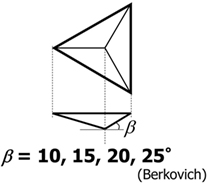
Figure 1. Schematic illustration of trigonal pyramid indenter. β is the face angle of the indenter and varied from 10° to 25°.
The sample used in this study was soda-lime glass for a microscope slide (Matsunami 0050, Japan; composition in wt% 71SiO2–13Na2O–1K2O–9CaO–4MgO–2Al2O3), with a thickness of about 1.2 mm. The maximum indentation load varied from 0.5 to 10.0 N, and the stroke rates during loading and unloading were kept constant at 0.1 µm/min. This stroke rate was controlled by the piezo-driver, and this stroke rate corresponds to the loading/unloading rate of about 1 N/min. The dwell time at a maximum load was constant at 1 s. All the indentation tests were performed under N2 flow to avoid humidity-assisted cracking.
Figure 2 shows examples of in situ contact regions of soda-lime glass under Figure 2A at 10° and Figure 2B at 25° (Berkovich) indenters, respectively. The indentation load is 1.0 N in both cases. In Figures 2A,B, fringe patterns around the contact region can be observed. This comes from the interference of light waves reflected from glass surface and the indenter. The interval between two dark fringes corresponds to the height difference of half a wavelength between the glass surface and the indenter (Chaudhri and Yoffe, 1981; Miyajima and Sakai, 2006; Muller and Green, 2010). As shown in the following sections, these fringe patterns are used to estimate the in situ sinking-in region around indentation periphery. Another characteristic in Figure 2 is the shape of the contact region. The contact region is not a regular triangle but concave one with bowed-in edges. The degree of bowing is remarkable especially under a blunter indenter with 10° face angle (Figure 2A). The bowed-in parameter is defined as the ratio of the length from the center to the corner, Lc, to the length from the center to the midpoint between corners, Lf, as shown in the inserted figures in Figure 3. The lengths Lc and Lf are determined from at least six indentations under a given indenter. If the contact region is a regular triangle, the bowed-in parameter, or the ratio of Lc to Lf, is 2, so that the bowed-in parameter is considered as a measure of the degree of concave shape. In Figure 3, the bowed-in parameter is plotted against the face angle of indenter. Regardless of the face angle, the bowed-in parameter is always larger than 2 for every indenter and decreases with increasing the face angle.
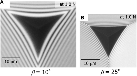
Figure 2. Photos of the indentation contact regions of soda-lime glass under (A) 10° and (B) 25° indenters. The indentation load is 1.0 N.
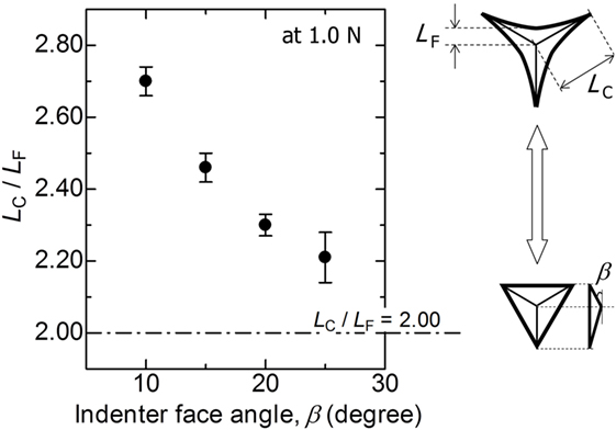
Figure 3. Relation between the bowed-in parameter, Lc/Lf and the face angle of indenter. The indentation load is 1.0 N. Error bars denote ±1 SD. The inserted figures represent schematic illustrations of the contact regions (concave and regular triangles).
Figure 4 shows the relations between the indentation load, P, and the in situ projected contact area, Ac (P–Ac curves), during a single load–unload test of soda-lime glass using four different trigonal pyramid indenters. The maximum indentation load was constant at 1.0 N. Closed and open symbols represent the projected contact area during loading and unloading, respectively. Each P–Ac curve was determined from at least six indentation tests using a given indenter. The projected contact area, defined as the area of the dark region shown in Figure 2, was calculated using the image processing program, ImageJ (Schneider et al., 2012; Yoshida et al., 2015). More precisely, the dark region extends a little the true contact area. However, no corrections were made to get the contact area from the obtained snapshot, because the extent of overestimation (1–3% for area) is within the experimental error, as shown in the previous papers (Muller and Green, 2010; Yoshida et al., 2015). In Figure 4, excellent linear relations can be seen in loading curves, as reported for some glasses and ceramics using their own indentation microscopes (Sakai et al., 2006; Yoshida et al., 2015). As for the unloading half cycle, on the other hand, the relation between load and in situ contact area is not linear due to complicated elastoplastic processes in glass (Sakai, 2003). From the slopes of the loading curves under a given indenter, the in situ Meyer hardness, which is the load divided by the in situ projected contact area, was determined. The results are shown in Table 1. The in situ Meyer hardness of soda-lime glass increases with increasing the face angle of indenter. This is in line with the results of previous report (Sakai and Nakano, 2004), where Meyer hardness of the materials, which include ductile metals, ceramics, glass, and organic polymer, increases with increasing the face angle of indenter. As discussed later, the Meyer hardness is not only a material parameter but depends on the indenter geometries.
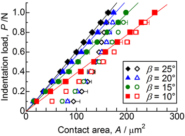
Figure 4. Relations between the indentation load, P, and the in situ projected contact area, Ac (P–Ac curves), during a single load–unload test of soda-lime glass using four different trigonal pyramid indenters with different face angles. The maximum indentation load is 1.0 N. Closed and open symbols represent the projected contact area during loading and unloading, respectively. Each P–Ac curve was determined from at least six indentation tests using a given indenter. Error bars denote ±1 SD. The solid lines are least square fits of the loading curves to linear functions.

Table 1. Some parameters obtained from in situ contact areas and from fringe patterns around indentation periphery.
The amount of sinking-in, or deformation downward with respect to the sample surface, can be determined from the fringe patterns shown in Figure 2. Schematic procedure for determining the amount of sinking-in is shown in Figure 5. Since the indentation microscope is mounted on the commercial inverted microscope with coaxial illumination, the incident light comes from the bottom of the sample. For simplicity, it is assumed that the outgoing light from the sample surface and the reflected light back from the indenter surface are perpendicular to the sample surface. The dark fringe appears if the gap distance, Dx, between the surfaces is an integer multiple of a half wavelength (550/2 nm) (Chaudhri and Yoffe, 1981). The gap angle, θ, which is always smaller than the face angle, β, can be estimated from the gap distance, Dx, and the interval between fringes, dx, as shown in Figure 5. The face angle, β, is precisely determined from the fringe patterns (not shown) just before indentation and listed in Table 1. From the gap angle, the face angle, and the position of the dark fringe, the surface profiles of glass under load can be estimated for different indenters. Figure 6 shows the surface profiles around the indentation peripheries. The indentation load is 0.5 N. The surface profile in Figure 6 represents the cross-section profile, which consists of the center of indentation and the centerline between two ridges. The ratio of the penetration depth, h, which can be measured using depth sensors attached to the indentation microscope, to the contact depth, hc, which can be calculated from the size of contact region, can be determined without any assumptions. The h/hc is called the geometrical factor, γ, which is a measure of amount of sinking-in. The obtained γ values are listed in Table 1. Figure 6 shows that the amount of sinking-in decreases with increasing the face angle of indenter.
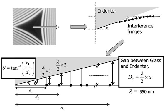
Figure 5. Schematic procedure for determining the gap angle, θ, the gap distance, Dx, between surfaces of indenter and glass. dx, where x is a natural number, is the interval between fringes. The wavelength of light, λ, for imaging is 550 nm.
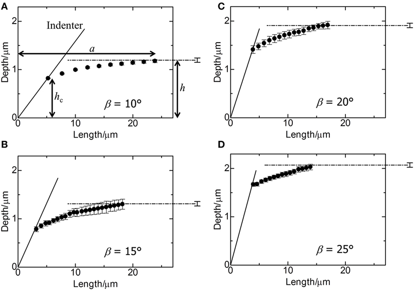
Figure 6. Surface profiles of soda-lime glass during indentation at a load of 0.5 N. The face angles of indenters are (A) 10°, (B) 15°, (C) 20°, and (D) 25°. The dashed-dotted line in each figure represents the initial profile of the surface before indentation. The solid line in each figure represents the inclined plane of the indenter. Error bars denote ±1 SD. a, h, and hc in (A) are the radius of the sinking-in region, the penetration depth, and the contact depth, respectively.
By using the indentation microscope, it becomes possible to estimate not only one-dimensional sinking-in parameter, γ, but also in-plane sinking-in as shown in Figure 6. Figure 7 shows the top views of contact regions of soda-lime glass under different indenters at a load of 0.5 N. In Figure 7, circles are drawn to represent the sinking-in region under an indenter assuming it is a circular shape. Error bars denote ±1 SD of diameter of sinking-in region, 2a. The radius, a, was determined from two kinds of cross-section profiles, which consist of the centerline between ridges (Figure 6) or one ridge of indenter (not shown). The parameter of in-plane sinking-in is defined in the following equation:
where Ac is the area of the contact region. Figure 8 shows two kind of sinking-in parameters, γ and γin-plane plotted against the face angle of indenter. These parameters are also shown in Table 1. Although error bars are quite large, it is found that both sinking-in parameters decrease with increasing the face angle of indenter and furthermore that the amount of in-plane sinking-in is larger than that of the conventional sink-in parameter, γ.
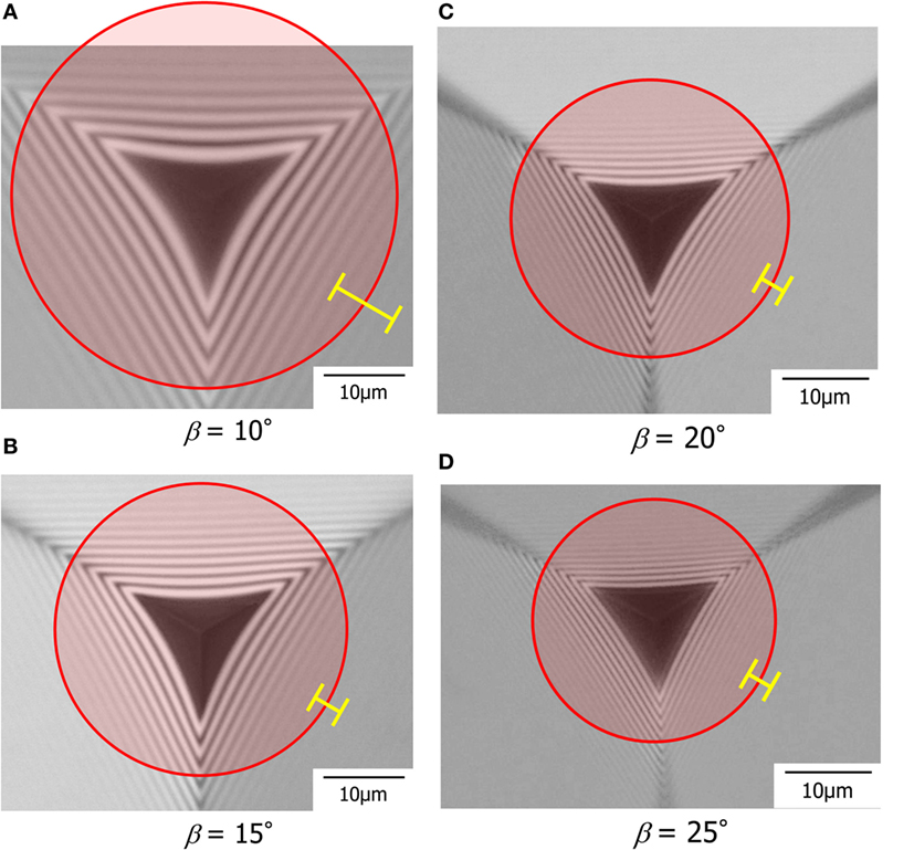
Figure 7. Top views of contact regions of soda-lime glass under different indenters at a load of 0.5 N. The face angles of indenters are (A) 10°, (B) 15°, (C) 20°, and (D) 25°. The regions enclosed by circles represent the sinking-in region. Error bars denote ±1 SD of diameter of sinking-in region.
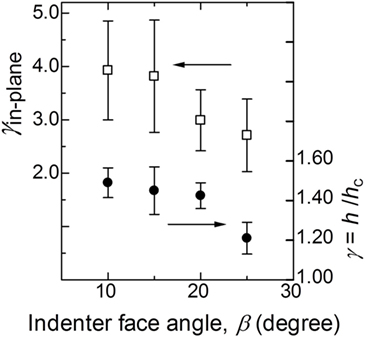
Figure 8. Relationships between sinking-in parameters, γ or γ in-plane, and the face angle of indenter. Error bars denote ±1 SD.
In our previous paper (Yoshida et al., 2015), the bowed-in geometries of the contact regions of some glasses under a Vickers indenter were discussed in terms of effects of composition and indentation load. It was considered that the bowed-in shape results from the pincushioning effect by the ridges of Vickers indenter (Lim and Chaudhri, 2006). Lim and Chaudhri attributed this bowing-in to the pincushioning of an elastic body, where the depth of contact is greater at the ridges of the indenter than the depth of the points between ridges. This is also the case of trigonal pyramid indenters used in this study. For example, Deuschle et al. (2009) reported the pincushioning effect of an elastomer [polydimethylsiloxane (PDMS)] under a Berkovich indenter. The bowed-in parameter estimated from their data is about 2.5 for PDMS under a Berkovich indenter. The bowed-in parameters larger than 2 (Figure 3) in the present study, and in situ sinking-in regions shown in Figures 6 and 7 confirm that the pincushioning occurs even in soda-lime glass under the edged indenters used. The bowed-in parameter of soda-lime glass under a Berkovich (25°) indenter is about 2.2 (Figure 3), which is smaller than that of PDMS. This suggests that plastic flow or shear flow, which causes the displaced volume to go up to the faces of the indenter, also occurs in soda-lime glass under the indenter. In Figure 3, the bowed-in parameter increases with decreasing the face angle of indenter. This implies that a blunter indenter results in a smaller contribution of shear flow. In our previous study (Yoshida et al., 2010), it was reported that the contribution of densification of soda-lime glass under the indenter increases with decreasing the face angle of indenter. In other words, glass under the blunter indenter prefers densification rather than shear flow. This also supports the present result on the indenter shape dependence of the bowed-in parameter.
It is well known that hardness of elastoplastic material depends on indenter geometries. Hardness is not only a material property but also depends on indenter geometries. The relationship shown in Eq. 2 is based on the expanding cavity model using a conical indenter (Johnson, 1987; Fischer-Cripps, 1997, 2007).
Meyer hardness, HM, depends on Young’s modulus, E, Poisson’s ratio, ν, yield stress, Y, and indenter face angle, β. Young’s modulus and Poisson’s ratio of soda-lime glass are 72 GPa and 0.20, respectively (Yoshida et al., 2015). The relationship in Eq. 2 is one reason why Meyer hardness of soda-lime glass increases with increasing the face angle of indenter.
Using Eq. 2, yield stress of glass can be estimated as shown in Table 1. It is found that the obtained yield stress varies with the indenter face angle. With increasing the face angle, yield stress also increases. In other words, an invariable yield stress cannot explain the indenter shape dependence of Meyer hardness obtained in this study. Varshneya (2007) suggested that there are two kinds of yield stress in glass, one is the shear yield stress and the other the dilatational (or hydrostatical) yield stress. There is very little information available on yield stress of glass, especially under pure shear. However, the response of glass under shear stress is of primary importance to understand threshold of deformation or cracking in glass. For example, these two types of yield criteria are indispensable to obtain the reliable constitutive model for the plastic deformation of glass (Lambropoulos et al., 1997; Lacroix et al., 2012; Keryvin et al., 2014). According to the constitutive models proposed, the yield criterion of glass varies with the type of loading. Under pure hydrostatic stress, plastic deformation of glass is controlled by the hydrostatic limit (hydrostatical yield stress) of glass. Under pure shear, on the other hand, yielding of glass occurs at the shear yield stress. The yield criterion varies with the contribution of shear component. It is well known that glasses can be grouped into two: normal and anomalous glasses. Normal glass prefers shear flow, and anomalous glass does densification (Arora et al., 1979). Not only glass composition but also indenter geometries change the deformation mechanism of glass. The effect of shear stress would be larger under a sharper indenter than under a blunter indenter. As stated above, glass prefers densification under the blunter indenter than under the sharper indenter (Yoshida et al., 2010). Thus, such change in deformation mechanism of glass results in a change in yield stress of glass as shown in Table 1.
In Figure 3, the bowed-in parameter decreases with increasing the face angle of indenter. This is due to indenter shape dependence of sinking-in around the indentation periphery. In Figures 6–8, sinking-in around the indentation can be experimentally confirmed for all trigonal pyramid indenters. It is also confirmed that the amount of sinking-in increases with decreasing the face angle of indenter.
In our previous study (Yoshida et al., 2015), it was suggested that the sink-in at the midpoint between the corners causes an edge crack along the edge of Vickers indentation imprint. Less amount of sinking-in for lead silicate glass results in radial or lateral cracking rather than edge cracking. In the present study, it is also expected that deformation behaviors of glass under trigonal pyramid indenters affect their cracking behaviors. Figure 9 shows photos of contact regions under load and residual imprints after unload. The maximum indentation load is 10 N. Figures 9C,E,G indicates examples of initial (edge) cracks of soda-lime glass during indentation using different indenters. Under a 10° indenter, as shown in Figures 9A,B, no crack can be observed up to 10 N during both loading and unloading. Although the γ value for 10° indenter is largest (Figure 8), the wider area of sinking-in, or the larger γin-plane, may result in smaller tensile stress around the indentation periphery. This is the reason that no edge crack was observed around the 10° indentation. The Meyer hardness also affects the stresses during both loading and unloading. According to Yoffe’s model (Yoffe, 1982), it was reported that the indentation-induced stresses can be normalized with respect to the hardness (Cook and Pharr, 1990; Sellappan et al., 2013). The stress driving each crack system, such as ring, radial, median, and lateral cracks, increases with increasing hardness of glass, although the effect of sinking-in was not taken into consideration in these papers. The Meyer hardness of soda-lime glass under a 10° indenter is 2.96 GPa (Table 1), which is about half of that under a 25° indenter. This is also the reason that no crack generates during the cycle of 10° indentation.
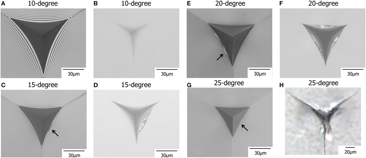
Figure 9. Photos of contact regions under load and residual imprints after unload. The maximum indentation load is 10 N. (A) Under a load of 10 N (a maximum load) and (B) after unload for 10° indenter. (C) Under a load of 5.8 N during unloading and (D) after unload for 15° indenter. (E) Under a load of 9.2 N during unloading and (F) after unload for 20° indenter. (G) Under a load of 6.1 N during loading and (H) after unload for 25° indenter. The arrows in (C,E,G) indicate the positions of initial edge cracks observed during loading or unloading.
The timing of edge crack initiation also depends on the face angle of indenter. Under a 25° indenter, edge cracking occurs during loading as shown in Figure 9G. However, 15° and 20° indenters create edge cracks only during unloading (Figures 9C,E). With decreasing the face angle of indenter, edge crack initiates in a late stage of the indentation cycle. The loads for edge cracking of 15° and 20° indenters are 5.8 N and 9.2 N during unloading, respectively. This indenter shape dependence of the timing of edge cracking is related to sinking-in behavior during loading. The sinking-in within a limited area results in edge cracking during loading. This is the case of 25° indenter. With increasing the sinking-in area, or with decreasing the face angle of indenter, tensile stress due to sinking-in decreases. In other words, the tensile stress would not be large enough to create edge cracks during loading. During unloading, however, the residual imprint disturbs elastic recovery as shown in Figure 10. This restoring force is the driving force for edge cracking during unloading. The indentation using the indenter with a smaller face angle leaves a shallower indentation imprint and shows larger elastic recovery. This is why a blunter indenter induces the edge crack in a late stage during unloading cycle.
In Figure 9H, radial cracks from the corners of imprint can be observed after complete unload. Under other indenters, there is no radial crack around the imprints. As stated above, a sharper indenter promotes shear flow rather than densification. The driving force of the radial crack is the residual stress driven by volume conservative shear flow (Lawn et al., 1980; Chiang et al., 1982; Yoffe, 1982; Cook and Pharr, 1990). This is the reason that only 25° indentation results in radial cracks after complete unload. Gross has already reported that the sharpness of indenter affects crack morphology in glass (Gross, 2012). However, he did not focus on sinking-in and on edge crack. During the cycle of indentation, glass responses both elastically and plastically. As shown in Figure 9, a small change in tip angle causes a large change in crack morphology and in the timing of cracking. The cracking phenomena are affected not only by the deformation mechanism in glass but also by elastic responses, such as the amount of one-dimensional sinking-in, the in-plane sinking-in region, the bowed-in parameter, and so on. Since brittleness of glass is closely connected with such mechanical responses of glass against contact with a foreign body, further experimental works on in situ deformation behaviors should be conducted to get more insight into compositional variation of indentation cracking in glass.
In this study, in situ observations of indentation deformation and cracking in soda-lime glass under different indenters were conducted using an indentation microscope. From the contact area of soda-lime glass under the indenter, in situ Meyer hardness was determined without any assumptions. The in situ Meyer hardness of soda-lime glass decreases with decreasing the face angle of indenter. This indenter shape dependence of Meyer hardness can be explained by variable yield stress depending on the indenter geometries. From the fringe patterns around the contact region, the amount of sinking-in around the indentation periphery was determined experimentally. It is found that both sinking-in parameters, γ and γin-plane, increase with decreasing the face angle of indenter. Under the indenter with a smaller face angle, soda-lime glass prefers elastic deformation or densification rather than shear flow. In situ deformation behavior also affects indentation cracking in glass. With decreasing the face angle of indenter, edge cracks generate in a late stage during unloading indentation cycle. The edge cracking is affected both by the amount of sinking-in and by the surface area of sinking-in region. A larger bowed-in parameter in a limited region, or with a smaller γin-plane, results in a higher risk of edge cracking. In addition, deformation mechanism, shear flow or densification, also affects crack type in glass. A sharper indenter with a larger face angle induces shear flow and results in radial cracking after unload. It is elucidated that sinking-in phenomenon in glass is remarkable under edged indenters and that in situ elastoplastic deformation in glass is closely related to following cracking behavior in the glass.
All authors listed have made substantial, direct, and intellectual contribution to the work and approved it for publication.
The authors declare that the research was conducted in the absence of any commercial or financial relationships that could be construed as a potential conflict of interest.
One of the authors (SY) would like to thank to the JSPS KAKENHI Grant Numbers 15H04124 and 16K06730.
Arora, A., Marshall, D. B., Lawn, B. R., and Swain, M. V. (1979). Indentation deformation/fracture of normal and anomalous glasses. J. Non Cryst. Solids 31, 415–428. doi: 10.1016/0022-3093(79)90154-6
Chaudhri, M. M., and Yoffe, E. H. (1981). The area of contact between a small sphere and a flat surface. Philos. Mag. A 44, 667–675. doi:10.1080/01418618108236169
Chiang, S. S., Marshall, D. B., and Evans, A. G. (1982). The response of solids to elastic/plastic indentation I. Stresses and residual stresses. J. Appl. Phys. 53, 298–311. doi:10.1063/1.329930
Cook, R. F., and Liniger, E. G. (1993). Kinetics of indentation cracking in glass. J. Am. Ceram. Soc. 76, 1096–1105. doi:10.1111/j.1151-2916.1993.tb03726.x
Cook, R. F., and Pharr, G. M. (1990). Direct observation of indentation cracking in glass and ceramics. J. Am. Ceram. Soc. 73, 787–817. doi:10.1111/j.1151-2916.1990.tb05119.x
Deuschle, J. K., Matthias Deuschle, H., Enders, S., and Arzt, E. (2009). Contact area determination in indentation testing of elastomers. J. Mater. Res. 24, 736–748. doi:10.1557/JMR.2009.0093
Fischer-Cripps, A. C. (1997). Elastic-plastic behaviour in materials loaded with a spherical indenter. J. Mater. Sci. 32, 727–736. doi:10.1023/A:1018552222072
Green, D. J. (1998). An Introduction to the Mechanical Properties of Ceramics. Cambridge: Cambridge University Press.
Gross, T. M. (2012). Deformation and cracking behavior of glasses indented with diamond tips of various sharpness. J. Non Cryst. Solids 358, 3445–3452. doi:10.1016/j.jnoncrysol.2012.01.052
Keryvin, V., Meng, J.-X., Gicquel, S., Guin, J.-P., Charleux, L., Sangleboeuf, J.-C., et al. (2014). Constitutive modeling of the densification process in silica glass under hydrostatic compression. Acta Mater. 62, 250–257. doi:10.1016/j.actamat.2013.07.067
Lacroix, R., Chomienne, V., Kermouche, G., Teisseire, J., Barthel, E., and Queste, S. (2012). Micropillar testing of amorphous silica. Int. J. Appl. Glass Sci. 3, 36–43. doi:10.1111/j.2041-1294.2011.00075.x
Lambropoulos, J. C., Xu, S., and Fang, T. (1997). Constitutive law for the densification of fused silica, with applications in polishing and microgrinding. J. Am. Ceram. Soc. 79, 1441–1452. doi:10.1111/j.1151-2916.1996.tb08748.x
Lawn, B. R., Dabbs, T. P., and Fairbanks, C. J. (1983). Kinetics of shear-activated indentation crack initiation in soda-lime glass. J. Mater. Sci. 18, 2785–2797. doi:10.1007/BF00547596
Lawn, B. R., Evans, A. G., and Marshall, D. B. (1980). Elastic/plastic indentation damage in ceramics: the median/radial crack system. J. Am. Ceram. Soc. 63, 574–581. doi:10.1111/j.1151-2916.1980.tb10768.x
Lim, Y. Y., and Chaudhri, M. M. (2006). Indentation of elastic solids with a rigid Vickers pyramidal indenter. Mech. Mater. 38, 1213–1228. doi:10.1016/j.mechmat.2006.04.006
Marshall, D. B., and Lawn, B. R. (1979). Residual stress effects in sharp-contact cracking: I. Indentation fracture mechanics. J. Mater. Sci. 14, 2001–2012. doi:10.1007/BF00551043
Miyajima, T., and Sakai, M. (2006). Optical indentation microscopy – a new family of instrumented indentation testing. Philos. Mag. 86, 5729–5737. doi:10.1080/14786430600788947
Morris, D. J., and Cook, R. F. (2004). In-situ observation of cube-corner indentation of soda-lime glass and fused silica. J. Am. Ceram. Soc. 87, 1494–1501. doi:10.1111/j.1551-2916.2004.01494.x
Muller, A. M., and Green, D. J. (2010). Elastic indentation response of float glass surfaces. J. Am. Ceram. Soc. 93, 209–216. doi:10.1111/j.1551-2916.2009.03377.x
Oliver, W. C., and Pharr, G. M. (1992). An improved technique for determining hardness and elastic modulus using load and displacement sensing indentation experiments. J. Mater. Res. 7, 1564–1583. doi:10.1557/JMR.1992.1564
Quinn, G. D., and Bradt, R. C. (2007). On the Vickers indentation fracture toughness test. J. Am. Ceram. Soc. 90, 673–680. doi:10.1111/j.1551-2916.2006.01482.x
Rouxel, T. (2015). Driving force for indentation cracking in glass: composition, pressure and temperature dependence. Philos. Trans. R. Soc. A 373, 20140140. doi:10.1098/rsta.2014.0140
Sakai, M. (2003). Elastic recovery in the unloading process of pyramidal microindentation. J. Mater. Res. 18, 1631–1640. doi:10.1557/JMR.2003.0224
Sakai, M., Hariki, N., and Miyajima, T. (2006). Instrumented indentation microscope: a powerful tool for the mechanical characterization in microscales. J. Mater. Res. 21, 2298–2303. doi:10.1557/jmr.2006.0276
Sakai, M., and Nakano, Y. (2004). Instrumented pyramidal and spherical indentation of polycrystalline graphite. J. Mater. Res. 19, 228–236. doi:10.1557/jmr.2004.19.1.228
Schneider, C. A., Rasband, W. S., and Eliceiri, K. W. (2012). NIH Image to ImageJ: 25 years of image analysis. Nat. Methods 9, 671–675. doi:10.1038/nmeth.2089
Sellappan, P., Rouxel, T., Celarie, F., Becker, E., Houizot, P., and Conradt, R. (2013). Composition dependence of indentation deformation and indentation cracking in glass. Acta Mater. 61, 5949–5965. doi:10.1016/j.actamat.2013.06.034
Tandon, R., and Cook, R. F. (1992). Cone crack nucleation at sharp contacts. J. Am. Ceram. Soc. 75, 2877–2880. doi:10.1111/j.1151-2916.1992.tb05522.x
Thurn, J., Morris, D. J., and Cook, R. F. (2002). Depth-sensing indentation at macroscopic dimensions. J. Mater. Res. 17, 2679–2690. doi:10.1557/JMR.2002.0388
Varshneya, A. (2007). Composition- and structure-dependence of brittleness in glass. Proceedings of XXIst Intl. Cong. Glass, S1 Edn. Strasbourg: International Commission on Glass.
Yoffe, E. H. (1982). Elastic stress fields causes by indenting brittle materials. Philos. Mag. A 46, 617–628. doi:10.1080/01418618208236917
Yoshida, S., Kato, M., Yokota, A., Sasaki, S., Yamada, A., Matsuoka, J., et al. (2015). Direct observation of indentation deformation and cracking of silicate glasses. J. Mater. Res. 30, 2291–2299. doi:10.1557/jmr.2015.214
Keywords: glass, hardness, indentation, densification, crack
Citation: Yoshida S, Wada K, Fujimura T, Yamada A, Kato M, Matsuoka J and Soga N (2016) Evaluation of Sinking-In and Cracking Behavior of Soda-Lime Glass under Varying Angle of Trigonal Pyramid Indenter. Front. Mater. 3:54. doi: 10.3389/fmats.2016.00054
Received: 30 September 2016; Accepted: 01 December 2016;
Published: 19 December 2016
Edited by:
Lothar Wondraczek, University of Jena, GermanyReviewed by:
Jean-Pierre Guin, University of Rennes 1, FranceCopyright: © 2016 Yoshida, Wada, Fujimura, Yamada, Kato, Matsuoka and Soga. This is an open-access article distributed under the terms of the Creative Commons Attribution License (CC BY). The use, distribution or reproduction in other forums is permitted, provided the original author(s) or licensor are credited and that the original publication in this journal is cited, in accordance with accepted academic practice. No use, distribution or reproduction is permitted which does not comply with these terms.
*Correspondence: Satoshi Yoshida, eW9zaGlkYUBtYXQudXNwLmFjLmpw
Disclaimer: All claims expressed in this article are solely those of the authors and do not necessarily represent those of their affiliated organizations, or those of the publisher, the editors and the reviewers. Any product that may be evaluated in this article or claim that may be made by its manufacturer is not guaranteed or endorsed by the publisher.
Research integrity at Frontiers

Learn more about the work of our research integrity team to safeguard the quality of each article we publish.