 Ning Fan
 Yixuan Hu1,2
 Hao Wu
 Jianxiong Jiang
- 1College of Civil Engineering and Architecture, Wenzhou University, Wenzhou, China
- 2Science Technology Department of Zhejiang Province, Key Laboratory of Engineering and Technology for Soft Soil Foundation and Tideland Reclamation of Zhejiang Province, Wenzhou University, Wenzhou, China
- 3Nanjing Hydraulic Research Institute, Nanjing, China
Recently, submerged floating tunnels have generated a lot of interest due to their unique cross-water traffic benefits. However, the destructive threat of submarine slide hazards was not fully considered in the design scheme of submerged floating tunnels, in particular to the feasibility of applying various cross-section forms on land to submerged floating tunnels under that hazard influence. This study mainly investigates the load effect of submerged floating tunnels with polygonal cross-sections (comprising three types: square, hexagon, and octagon) under the impact of submarine slides, via a computational fluid dynamics (CFD) approach. Results show that the impact forces produced by submarine slides on submerged floating tunnels are significant (e.g., submarine slides with a velocity of 4 m/s may produce a force level near 1×10⁵ N/m), where the horizontal impact force components should be given priority consideration based on the general working environment of submerged floating tunnels. Compared with typical circle tunnels, polygonal tunnels suffer higher impact forces, and the polygonal types with fewer edges show a greater impact force. Finally, a simplified force evaluation approach for the submerged floating tunnel with polygonal cross-sections is proposed for guiding the relevant engineering design.
1 Introduction
The submerged floating tunnel design scheme was first proposed in the late 1960s to be used for solving the traffic link between the Sicily and Italian mainland (Straits of Messina) (Anon, 1971). Relevant patent techniques can even be traced back to the 19th century (Jakobsen, 2010). Submerged floating tunnels are special cross-water traffic structures that maintain balance by the structure buoyancy and anchor cable tension. Compared with other structures (e.g., bridges and immersed tube tunnels) of cross-water transportation, the main benefits of the submerged floating tunnel include (Jiang et al., 2018; Kim and Kwak, 2022; Kwon et al., 2022): (i) it is suspended at a certain depth underwater so that it does not affect the water surface navigation and is basically unaffected by the adverse weather (e.g., strong breeze) on the water surface (compared with bridges); (ii) its engineering layout position is relatively shallow so that the construction angle and length of the structures are smaller and the effect of complex seabed topography (e.g., submarine canyon) can be ignored (compared with immersed tube tunnels); (iii) its structural features of prefabricated segmental connection are not limited by the water depth and structure span so that the construction stability is easier to guarantee. The above benefits of submerged floating tunnels show potential and competitiveness in the technical solutions of cross-water transportation, which currently has become a research hotspot in industry and academia (e.g., Ingerslev, 2010; Martinelli et al., 2011; Kristoffersen et al., 2019; Jin and Kim, 2020; Yang et al., 2021).
Structural stability and safety of submerged floating tunnels under the effect of a changeable and dangerous underwater environment (Borja, 2014; Duarte, 2014; Liu et al., 2022) are the first issues to be considered. Wave loads and current loads are usually considered the main external environmental loads for the submerged floating tunnel design (Jakobsen, 2010; Seo et al., 2015). For example, the current-induced vibrations of submerged floating tunnels were investigated by circulating water channel experiments (Yoshihara et al., 1996). It found that the tunnel structure shows patterns of severe random vibration under the effect of irregular shedding vortices, with larger current velocity conditions. The dynamic response of submerged floating tunnels due to waves was analyzed, and the wave forces were evaluated by applying both the Morrison’s equation and the boundary element method (Kunisu, 2010). Recently, the wave-induced hydroelastic response and flow-induced vibrations of submerged floating tunnels under the first and second-order wave loads were discussed via the SIMO-RIFLEX numerical software, which served for the design of crossing Sognefjorden of Norway (Deng et al., 2022). In addition, some external threat factors on submerged floating tunnel structures have also been considered, such as the impact from sea ices (e.g., Jakobsen, 2010; Eik, 2011; Haeberli and Whiteman, 2015), sinking ships (e.g., Vries, 1988; Lee et al., 2013), and hooking of trawling gears or anchor lines (e.g., Fitriyah et al., 2017; Xiang et al., 2020). However, frequent and widely distributed submarine slide, as an important environmental load factor (Jia et al., 2016; Dong et al., 2017; Wang et al., 2018; Nian et al., 2019; Fan et al., 2022a; Tian et al., 2023), has not been considered. Until recent years, the study of Fan et al. (2022b) first analyzed the impact action of submarine slides with different thicknesses on circular submerged floating tunnels, and an evaluation approach for the impact forces of submarine slides was proposed.
At present, a variety of design types of submerged floating tunnels for different underwater engineering conditions have been suggested, which mainly refer to the construction experience of land tunnels, as shown in Figure 1. Among them, the design schemes of the polygonal cross-section are common (Anon, 1971; Kanie, 2010; Jiang et al., 2018). However, from a viewpoint of submarine slide hazards, the study on the safety of those design types of submerged floating tunnels is insufficient. The catastrophic events of underwater structures caused by submarine slides in history (e.g., Hampton et al., 1996; Chaytor et al., 2009; Nugraha et al., 2022) should give enough warning for the design of submerged floating tunnels.
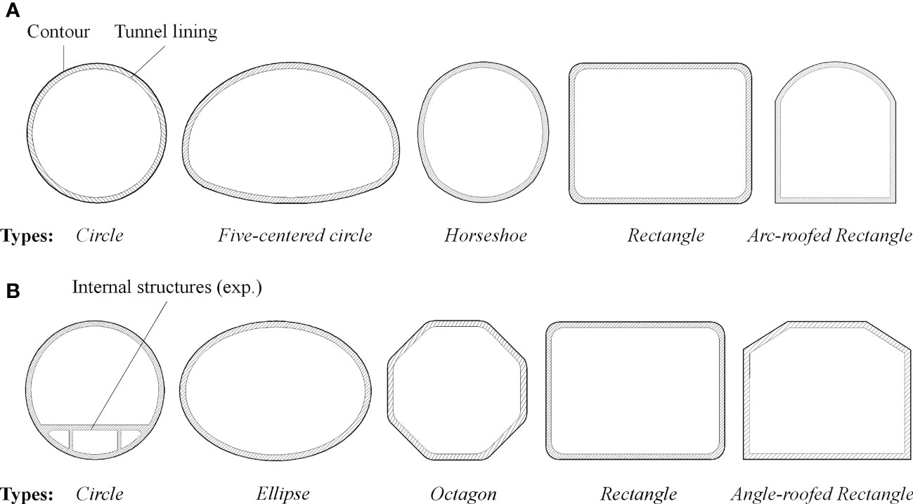
Figure 1 Typical cross-section types of land tunnels (A) and undersea tunnels (B).
This study focuses on the load effect of submerged floating tunnels with polygonal cross-sections near potential submarine slide areas. The main objective is to clarify the force levels under the impact of submarine slides and evaluate the impact forces, in order to provide multi-angle references for the safety design of submerged floating tunnels. For this reason, a series of numerical analysis have been carried out, and a simplified evaluation approach for the impact forces of submarine slides on the submerged floating tunnel with polygonal cross-sections is proposed. In the end, an application case for the evaluation approach is provided.
2 Design of polygonal cross-section tunnels
Considering the polygonal cross-sections account for a considerable proportion of the design of submerged floating tunnels, this study selects three regular polygons (with the same size of edges and included angles) as representatives for discussion, including the square, hexagon and octagon, as shown in Figure 2. Generally, the outer diameter of submerged floating tunnels with circle cross-section tunnels is in a range of 4-23 m (Jakobsen, 2010; Kim and Kwak, 2022). Here, the vertical contour sizes (recorded as D) of those polygons all adopt 14 m, and the upper and lower sides of the tunnel adopt straight edges (see Figure 2A) to ensure the same impact section size in the movement direction of submarine slides. The rest edges were set according to the regular polygon rules. Taking the submerged floating tunnel with an octagon cross-section as an example, Figure 2B shows a 3-dimensional view of the tunnel with the polygonal cross-section design. The in-place stability of suspended floating tunnels usually relies on the anchor and foundation system (as shown in Figure 2B) or suspended structures on the sea surface. In this study, the influence of those stability structures is not considered, and the tunnel body is treated as fixed and undeformed.
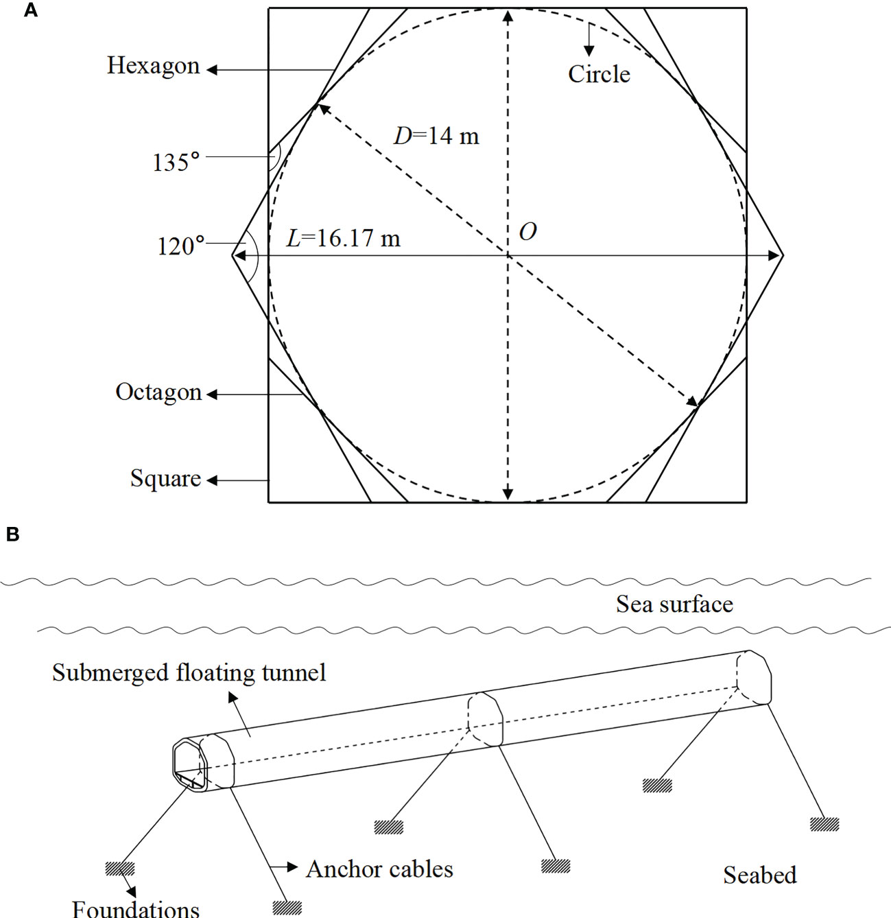
Figure 2 Cross-section types of polygonal cross-sections (square, hexagon, and octagon) (A) and 3-dimensional views (an example of the submerged floating tunnel with an octagon cross-section) tunnels discussed in this study (B).
3 CFD simulation approach and setup
In recent years, the computational fluid dynamics (CFD) simulation approach has been widely used in the studies of submarine slide motion (e.g., Gauer et al., 2005; Acosta et al., 2017; Fan et al., 2022a; Fan et al., 2022b) and its interaction with structures (e.g., Zakeri et al., 2009; Zakeri and Hawlader, 2013; Liu et al., 2015; Fan et al., 2018; Fan et al., 2019; Qian and Das, 2019; Sahdi et al., 2019; Fan et al., 2020a; Guo et al., 2021; Guo et al., 2022), due to the numerical solution stability and speed advantages on the multi-phase coupled flow field. To reproduce the influence of submarine slides on submerged floating tunnels in the underwater environment, the ANSYS-CFX numerical software based on the CFD simulation approach is employed in this study.
3.1 Computational domain and boundaries
In the ANSYS-CFX, a 3-dimensional computational domain, 16D (X-axis, where D is 14 m) × 12D (Y-axis) × 2D (Z-axis), was built as shown in Figure 3. The computational domain simulated a segment of submerged floating tunnels along the tunnel axis (in the Z-axis), and its bottom boundary was treated as the seabed surface. The position of the polygonal tunnels was set against a distance of 5.5D from the left boundary of the computational domain to the tunnel center (here, the tunnel structure was set as fixed to reflect its normal working state). The gap between the tunnel bottom and seabed surface (Hps) was adopted 2D to reduce the influence of velocity boundary layers on the seabed surface (Fan et al., 2021a). Then, the computational domain was meshed via the ICEM-CFD module in the ANSYS Workbench, based on the rules of using tetrahedral elements. The maximum element size was 10 m, and the grids near the tunnel and seabed were refined surface to ensure simulation accuracy. The grid refinement was constructed by adding five layers of very fine mesh around the tunnel and seabed surface, and the area around the tunnel surface was further refined at a distance of 1.5D. As a consequence, more than 240,000 tetrahedral elements were generated in the computational domain.
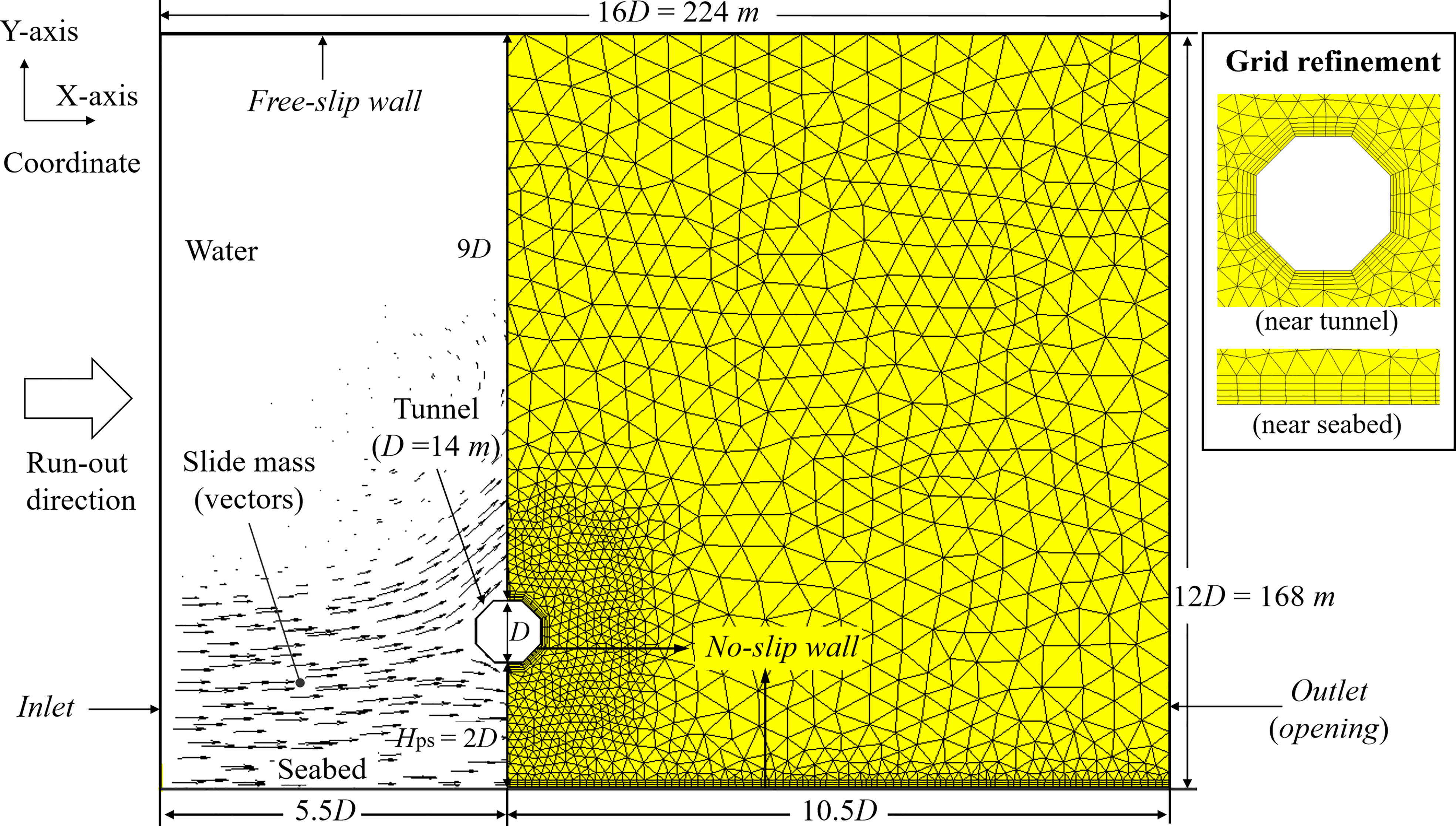
Figure 3 CFD numerical modelling on the interaction between the submarine slides and tunnels (an example of the octagon section).
At the initial state, the computational domain was full of water. Submarine slides with different thickness and velocity conditions will enter the computational domain from the left boundary (i.e., inlet boundary) and move along the X-axis after the simulation starts. Correspondingly, the right boundary (i.e., outlet boundary) of the computational domain was set as an opening boundary so that the fluid can flow out. The bottom boundary was a no-slip wall with equivalent roughness of 0.5 mm to reflect a sand seabed surface (DNVGL-RP-F109, 2021). The surface of the tunnel structure was also modeled by the no-slip wall with equivalent roughness of 0.0015 mm to reflect a concrete surface covered with a thin layer of asphalt coating (DNVGL-RP-F105, 2017). In addition, the top boundary was a free-slip wall. Based on the above settings, the interaction between submarine slides and tunnels in the computational domain was achieved, and the example of submarine slide mass motion in a vector form was shown in Figure 3.
3.2 Material properties
The physical state of submarine slide mass may evolve with the development of the motion process under certain environment conditions, from the solid state (glide block) to the fluid state (debris flow or turbidity current) (Dong et al., 2017; Fan et al., 2018; Guo et al., 2021). In this study, the submarine slide mass was set as the fluid state which shows a greater influence on the surrounding environment. For the fluid-state slide mass, it was generally considered a non-Newtonian fluid and followed the shear thinning rules (e.g., Zakeri et al., 2008; Zakeri et al., 2009; Boukpeti et al., 2012; Randolph and White, 2012; Fan et al., 2020b; Guo et al., 2023). That means that the relationship between shear stress and shear strain rate is nonlinear, and the apparent viscosity decreases gradually with increasing shear strain rates. In this study, a rheological material model by Fan et al. (2020b) was adopted to reflect a general seabed sediment situation as follows:
where su,0 is the initial undrained shear strength, Pa; is the yield strength in the initial state, Pa; is the shear strain rate corresponding to yield point, s-1; ηy,0 is the apparent viscosity at yield point in the initial state, Pa·s; n0 is the liquidity index in the initial state; su,rem is the undrained shear strength of the slide mass at remolded state, Pa; is the yield strength, Pa; ηy,rem is the yield viscosity, Pa·s; is the shear strain rate, s-1; nrem is a fluid parameter; and v is the velocity of the submarine slide mass, m/s. The submarine slide mass was assumed fully disturbed and reshaped in this study, so Eq. 2 was adopted in this study. Other parameters were set as follows: =160.41 Pa, ηy,rem=801.25 Pa·s, and nrem=0.38. Those parameters were estimated based on typical seabed soils with a soil fluid limit of 50%, a water content of 100%, and a density of 1480 kg/m³ (Fan et al., 2020b). In addition, the effect of temperature on submarine slide mass materials was not considered in this study (Nian et al., 2018).
3.3 Other details
The main numerical discrete methods in the ANSYS-CFX for solving the flow control equation are the finite volume method (FVM) (CFX 2017). The computational domain will be divided into a finite number of control volume elements. The characteristic variables maintain good conservation laws in the control volume elements, and the physical meaning of each item in discrete equations is clear. In this study, the specific spatial discrete scheme was selected the second-order upwind scheme. The standard k-ϵ model was adopted for turbulence enclosure. The reliability of the above numerical modelling process on submarine slide-structure interaction has been well verified by the data from flume experiments and geo-centrifuge experiments in previous studies (e.g., Zakeri et al., 2009; Zakeri and Hawlader, 2013; Fan et al., 2018; Fan et al., 2021a).
In summary, a total of 252 numerical cases have been carried out in this study, and the detailed case parameters can be found in Table 1. The variable parameters related to submarine slides are run-out velocities (7 variables from 0.2 to 5.0 m/s) and the ratios of slide mass thickness to the diameter of the submerged floating tunnel (12 variables from 0.5 to 11.0) of the slide mass; while the variable parameters related to submerged floating tunnels are cross-section types (three variables as shown in Figure 2A).
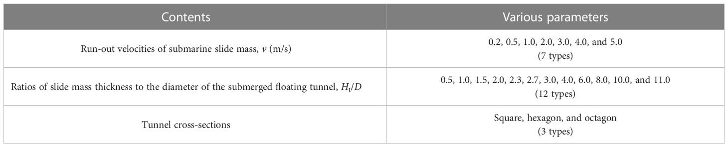
Table 1 Parameter settings of numerical cases.
4 Results analysis
4.1 Load effect caused by submarine slides
Load effect caused by submarine slides refers to the external impact forces on the submerged floating tunnel structure produced by the submarine slides in this study. Here, the impact forces can be further divided into horizontal and vertical force components (FH and FV, respectively), according to the co-planar relationships (the plane perpendicular to the tunnel axis line) of submarine slide-tunnel interaction. Load direction of horizontal impact forces is consistent with the run-out direction of submarine slides, while the vertical impact forces are vertical to the run-out direction. Results of the horizontal and vertical impact forces (normalized by su·A) during submarine slide-tunnel interaction with different run-out velocity conditions can be found in Figures 4 and Figure 5, where an example of the tunnel with octagon section and the Ht/D display six types (0.5, 1.0, 2.0, 3.0, 6.0, and 8.0) are presented.
Figure 4 Horizontal impact force curves during submarine slide-tunnel interaction at different thicknesses of slide mass (an example of the octagon section). Ratios of slide mass thickness/diameter = 0.5 (A), 1.0 (B), 2.0 (C), 3.0 (D), 6.0 (E), and 8.0 (F).
Figure 5 Vertical impact force curves during submarine slide-tunnel interaction at different thicknesses of slide mass (an example of the octagon section): ratios of slide mass thickness/diameter = 0.5 (A), 1.0 (B), 2.0 (C), 3.0 (D), 6.0 (E), and 8.0 (F).
According to previous studies (e.g., Fan et al., 2018; Guo et al., 2021; Fan et al., 2022a) on the interaction between submarine slides and cylindrical structures (e.g., pipelines), typical variation curve of interaction forces can be distinguished into two stages: instantaneous and stable stages. The former is characterized by the peak forces (maximum value) of the instantaneous moment that the submarine slides first impact structures, and the latter is characterized by the stable forces (average value) after submarine slides continuously impact structures for a period of time. In Figure 4, the development of horizontal impact force curves of different velocities is toward a similar trend. The peak forces of the horizontal impact curve are low, and stable forces tend to be 0, when the slide mass thicknesses (Ht/D) are lower than the tunnel-seabed gap (Hps/D=2.0), as shown in Figures 4A, B. That means that the submarine slide with a thinner body and a main flow path downside tunnel will not seriously affect the tunnel stability. However, the impact forces produced by submarine slides need to be seriously considered once the sliding body is thicker and higher than the tunnel-seabed gap. From Figures 4C-F, the value of horizontal impact forces (concludes the peak and stable forces) significantly grows with Ht/D increasing, but the growing degree gradually reduces after the submarine slide mass floods the tunnel (slide mass thickness is high and beyond the top of tunnel, e.g., Ht/D=6.0 and 8.0). The actual loading area of tunnel structure will be added with increasing Ht/D. Until the tunnel structure is flooded in the sliding body, the force growing degree will weaken.
For the vertical impact force curves shown in Figure 5, some variation trends are similar to that of horizontal impact forces. When Ht/D is lower than 2.0 (see Figures 5A, B), peak vertical impact forces are also relatively lower and the stable vertical impact forces are near 0. However, the peak and stable impact forces are not shown a continuously growing trend with increasing thicknesses of slide mass after Ht/D is larger than 2.0 (see Figures 5C-F). That is mainly related to the formation mechanism of vertical force components during submarine slide mass-tunnel interaction. Based on the study of Fan et al. (2021b), the vertical force components are mainly formed by the flow field difference between the upper and lower sides of a structure. Thus, the vertical impact forces are mainly caused by the slide mass flow at the lower side of the tunnel and a symmetric flow field cannot be formed at the upper and lower side of tunnel for partial impact actions of submarine slides on tunnel structure (e.g., Figure 5C). After the thickness of slide mass is high and floods the tunnel, the flow field around the upper and lower side of tunnel will be symmetric. The variation form of vertical impact force curves becomes similar (see Figures 5E, F), where the periodic vibration at high velocity conditions is derived from couples vortex periodically shedding on the rear side of the tunnel (Patnana et al., 2009).
Further, the peak horizontal and vertical impact force data at different velocity and thickness conditions are collected and shown in Figure 6 (an example of the tunnel with an octagon section). In this study, the influence of run-out velocity of submarine slide mass on impact forces is reflected by a dimensionless parameter, the Reynolds number. The Reynolds number refers to the ratio of inertial force and friction force from the physical meaning, which is commonly used to describe the characteristics of fluid flow and to determine the resistance of an object in a flow (Schlichting and Gersten, 2017). Since submarine slides are typical non-Newtonian fluids as described in Section 3, the mathematical expression of the Reynolds number of submarine slides is usually adopted as Eq. 4 (derived by Zakeri et al., 2008).
Figure 6 Peak impact forces during submarine slide-tunnel interaction at different Reynolds numbers (an example of the octagon section): horizontal impact forces (A) and vertical impact forces (B).
where Renon-Newtonian is the Reynolds number of submarine slides; ρ is the density of submarine slide mass (kg/m3); μapp is the apparent viscosity of submarine slide mass (Pa·s); thus, (ρ·v2) reflects the inertial force of submarine slides and (μapp·=τ) reflects the friction force.
Figure 6 shows that the peak horizontal and vertical impact forces increase with increasing Reynolds numbers. In addition, the load level of peak horizontal impact forces is higher than that of peak vertical impact forces, which is mainly related to the tunnel-seabed gap size (two times of tunnel diameter) in this study. Meanwhile, the influence of the thickness conditions of submarine slides on peak impact forces can also be found, and similar results of previous studies (forces during the submarine slide-pipeline interaction, with a thicker thickness compared with pipelines and gap ratio of 2.0, from Fan et al., 2021a; Fan et al., 2021b) are also presented and compared. It can be seen that the impact forces vary greatly with different slide mass thicknesses; In addition, some results of this study (Ht/D=10.0 and 11.0, with a larger thickness) are close to those of previous studies.
4.2 Comparison with circle cross-section tunnel
The impact forces of submerged floating tunnels with circle cross-sections encountered the submarine slide hazards have been discussed by Fan et al. (2022b). The influence range of the slide mass thickness on the peak impact forces was found limited to Ht/D of approximately -1.5 ~ 8.0 based on the bottom edge of the tunnel (where the negative value indicates a downward direction). If the slide mass thickness is in this range, the impact forces can be regarded as a partial impact state, and the impact forces are in a flooded state when the thickness is greater than the upper limit of this range. An evaluation approach for the impact forces caused by submarine slides on circle submerged floating tunnels was provided (Fan et al., 2022b) and expressed as:
where FH(or V)-p is the peak horizontal (or vertical) impact forces, N; NH (or V) and CH (or V) are the model coefficients of the horizontal (or vertical) impact forces, respectively; A is the cross-sectional area under the impact of submarine slides along the tunnel axis, m2; and ΔH(or V)-p is the deviation coefficient that reflects the deviation of FH(or V)-p between the partial and flooded impact states. It should be noted that the expression in the flooded impact state is a hybrid geotechnical-fluid dynamics framework for evaluating the impact forces during the submarine slide-cylindrical structure interaction with a large enough slide mass thickness. The determination method of those coefficient values can refer to previous studies (Fan et al., 2021a; Fan et al., 2021b).
To compare the differences between the impact forces of the tunnel with polygonal cross-sections and with the circle cross-section, deviation coefficients of the peak horizontal and vertical impact forces at different thickness conditions are shown in Figures 7, 8, respectively. The gray area in the figures represents a reference position of the tunnel against the seabed.
Figure 7 Deviation coefficients of the horizontal peak impact forces versus normalized thicknesses of the slide mass.
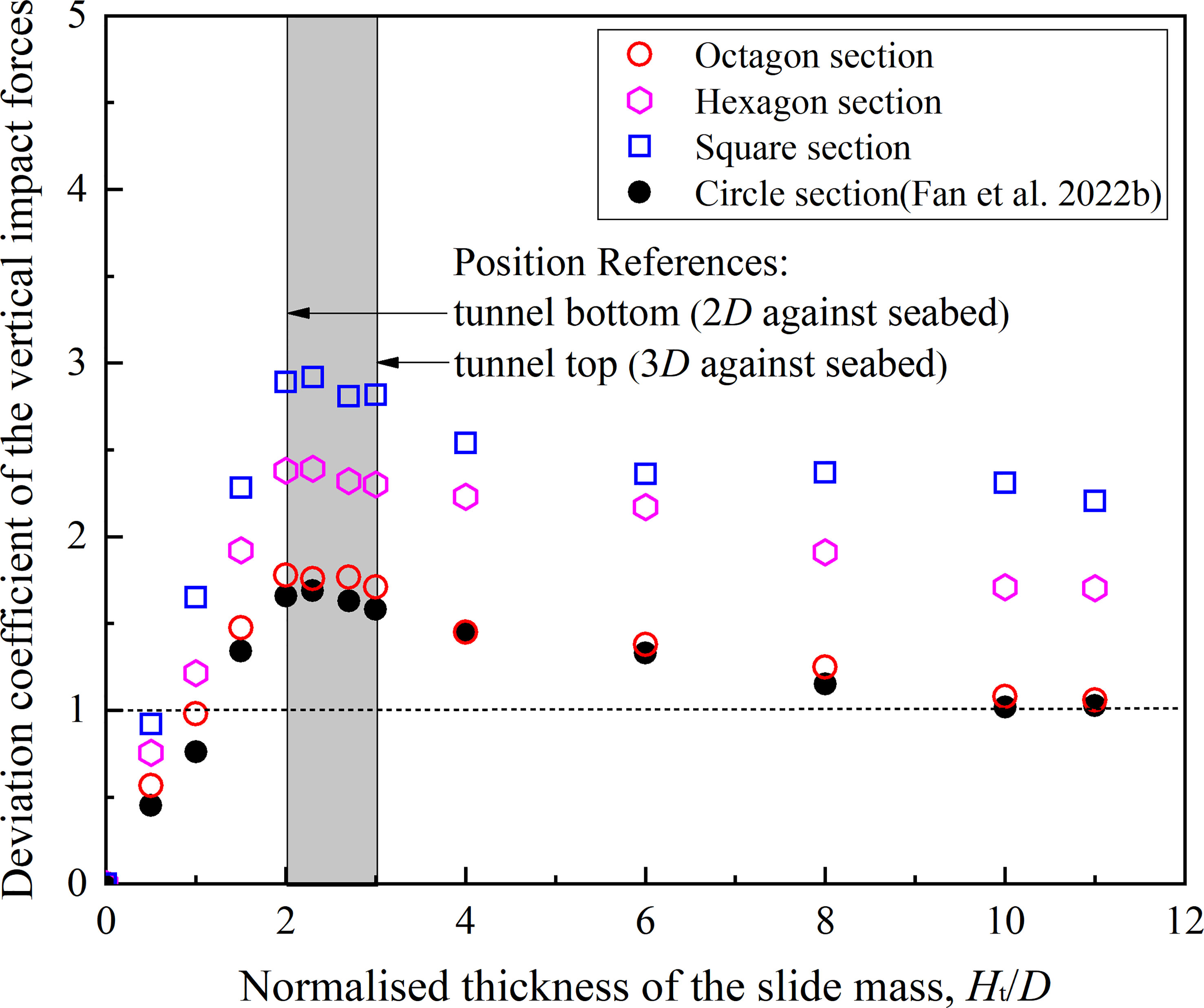
Figure 8 Deviation coefficients of the vertical peak impact forces versus normalized thicknesses of the slide mass.
Results in Figure 7 show that deviation coefficients of the tunnel with polygonal cross-sections have a similar increasing trend as the tunnel with the circle cross-section, with increasing thicknesses. However, the deviation coefficients of the polygonal tunnel are higher than that of the circular tunnel, and the degree of difference between polygonal and circular tunnels decreases with the increase of the number of edges (the difference degree of the square-sectional tunnel is the largest; while the data of the octagon-sectional tunnel approach to that of the circular tunnel). That is mainly related to the higher resistance of the tunnels with a polygonal cross-section in the flow field of submarine slide mass. Figure 9 shows the flow velocity field status of polygonal and circular cross-section tunnels under the impact of submarine slides at the same time (where the color in the figure means volume fraction; thus red and blue color represents slide mass and water respectively, and the colors in that range represent the transition between them; black lines represent the flow streamlines). The flow resistance of the square-sectional tunnel is obviously greater than that of other section forms. Hence, the largest horizontal impact force is generated. In addition, the shape of the octagon is closer to a circle than others, and its horizontal impact force is similar to the circular tunnel.
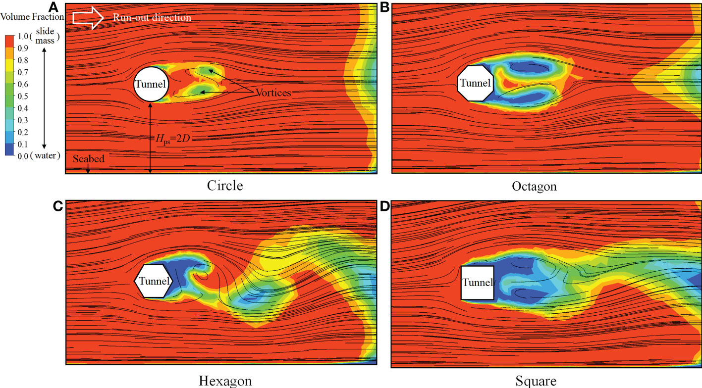
Figure 9 Flow velocity field comparison between the circular and polygonal cross-section tunnels under the impact of submarine slides: circle (A), octagon (B), hexagon (C), and square (D).
For the deviation coefficients of the peak vertical impact forces as shown in Figure 8, the data variation trend of polygonal tunnels is also similar to the circular tunnel. With increasing Ht/D, the deviation coefficients first increase to a maximum value (at Ht/D ~ 2.3) and then gradually decrease to a relatively stable value. The maximum vertical impact forces occurred at that thickness value are mainly caused by the upward flow field at a partial impact state. In addition, the degree of difference of vertical impact forces between polygonal and circular tunnels is also similar to the horizontal impact forces. The fewer the edges of the polygonal cross-section, the greater the vertical forces.
5 Evaluation approach and application case
Through the above results analysis, existing evaluation approaches show limitations in predicting the impact forces of submerged floating tunnels with polygonal cross-section under the impact of submarine slides. On the one hand, the approach for evaluating the impact forces during the submarine slides-cylindrical structures (e.g., pipelines, from Fan et al., 2021a; Fan et al., 2021b) interaction cannot cover the results at a partial impact state. On the other hand, the impact forces during submarine slides-tunnels interaction of the polygonal tunnel have differences from circular tunnels. To make a load prediction for the design of polygonal tunnels near potential submarine slide hazards zone, a simplified evaluation approach based on the load prediction of circular tunnels (Eq. 6) is proposed as:
where GH(or V)-p is the peak horizontal (or vertical) impact forces of polygonal tunnels during submarine slides-tunnels interaction, and N; δH(or V) is the correction factor of the peak horizontal (or vertical) impact forces, which can be adopted from Figure 10. In Figure 10, the data of impact forces of polygonal tunnels divided by that of circular tunnels are displayed under different thickness conditions. Results show that the correction factors of the peak horizontal and vertical impact forces are approximately constant, except for individual results at lower thickness conditions. Here, the results in a Ht/D range of 3.0-11.0 are averaged as the correction factors; thus, δH of the square-sectional tunnel is 1.31, the hexagon-sectional tunnel is 1.16, and the octagon-sectional tunnel is 1.02; similarly, δV of the square-sectional tunnel is 1.95, the hexagon-sectional tunnel is 1.60, and the octagon-sectional tunnel is 1.05. It should be noted that the polygonal cross-section with fewer than four edges (e.g., triangle) will not be used for tunnel design generally, and the result tends to be the circular tunnel when the edge number of polygonal cross-sections exceeds eight. Therefore, the correction factors given in this study are representative and can essentially meet the application requirements.
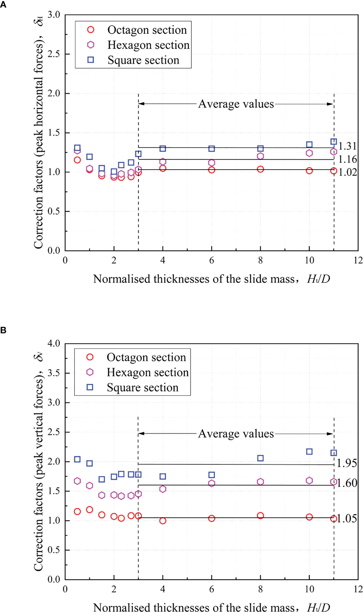
Figure 10 Correction factors of the submarine slide impact force: peak horizontal (A) and vertical impact forces (B).
From the perspective of submerged floating tunnel design, tunnels using a polygonal cross-section will increase the load effect from submarine slides to different degrees, and the increasing degree is generally not more than two times. If a tunnel scheme with polygonal cross-sections is adopted, the potential load effect caused by submarine slides can be determined by the simplified evaluation approach (Eq. 6) in this study.
Next, the application of this simplified evaluation approach is introduced through a computational case. Considering this scenario: (i) there is a submerged floating tunnel with a hexagon cross-section and vertical contour size (diameter) of 15 m, which is located at a suspended distance against the seabed of 45 m (so δH=1.16, δV=1.60, D=15 m, and Hps/D=3.0); (ii) submarine sediments near the tunnel are triggered and generate the slide movement. When the slide mass reaches the location of the tunnel, the predicted velocities of slide mass (v) are 0.2-4 m/s, thickness is 60 m (Ht/D=4.0), and density (ρ) is 1500 kg/m3; (iii) the rheological strength model of slide mass is same with this study () [these parameters are obtained by measuring the shear strength of remolded soil in the South China Sea (Fan et al., 2020b)]. In addition, the load is considered as the force per unit length along the tunnel axis (units of N/m).
The calculation process is as follows:
(i) based on Eq. 3, = 0.013 - 0.267 (s-1), then su = 160.41 + 25.64 × 0.38= 165.38 - 175.93 (Pa);
(ii) based on Eq. 4, Renon-Newtonian = 0.36 - 136.42;
(iii) based on Eq. 5 (flooded impact state), FH-p = 2.02×10⁴ - 2.64×10⁵ (N/m) and FV-p = 0.52×10³ - 3.65×10⁴ (N/m), where NH (or V) and CH (or V) can be determined from previous studies (Fan et al., 2021a; Fan et al., 2021b); in this case, NH = 7.88, CH = 1.35, NV = 0.17, and CV = 0.2;
(iv) based on the previous study (Fan et al., 2022b), the deviation coefficients ΔH-p = 0.57 and ΔV-p = 1.60;
(v) based on Eq. 5 (partial impact state), FH-p = 1.15×10⁴ - 1.50×10⁵ (N/m) and FV-p = 0.83×10³ - 0.58×10⁵ (N/m);
(vi) finally, based on Eq. 6, the horizontal and vertical impact forces caused by submarine slides are: GH-p = 1.16×FH-p = 1.33×10⁴ - 1.74×10⁵ (N/m) and GV-p = 1.60×FV-p = 1.33×10³ - 0.93×10⁵ (N/m).
6 Conclusions
This study has investigated the load effect (contains horizontal and vertical impact forces) of submerged floating tunnels with polygonal cross-sections under the impact of submarine slides, via a series of computational fluid dynamics (CFD) numerical simulations. Three representative polygonal cross-sections (square, hexagon, and octagon) are considered. CFD numerical simulations were carried out at different thicknesses (Ht/D of 0.5-11.0) and velocities (0.2-6 m/s; thus Reynolds numbers of 0.36-298) of submarine slides. The main conclusions drawn from this study are shown as follows:
(1) The load effect produced by submarine slides is very significant for submerged floating tunnels and is affected by the thickness and velocity characteristics of submarine slide mass movement. In particular, the load level will be high, and periodic vibration may occur after the tunnel structure is flooded in the slide mass. In addition, the horizontal impact forces caused by submarine slides (a higher load level) should be mainly considered due to the suspended status of submerged floating tunnels (i.e., a larger tunnel-seabed gap).
(2) Compared with the submerged floating tunnels with circle cross-sections, the impact forces during the interaction between the submarine slide and tunnel with polygonal cross-sections are increased to different degrees. The polygonal form with fewer edges shows a greater impact force (which means the square-sectional tunnel has the largest impact forces, while the octagon-sectional tunnel has the lowest impact forces approaching the circle-sectional tunnel).
(3) To fully consider the load effect of submarine slide hazards in the submerged floating tunnel design, a simplified evaluation approach for the tunnel with polygonal cross-sections is proposed to determine the load effect. An application case of the proposed approach is also presented. The case shows that the impact forces caused by submarine slides can be determined in a simple and reliable manner.
The current study on the effect of submarine slides on submerged floating tunnels is still insufficient. More relevant factors (e.g., the impact action of submarine slides with different angles; the rheological behavior of submarine slides) need to be further discussed, and more relevant physical model experiments need to be carried out in the future.
Data availability statement
The original contributions presented in the study are included in the article/supplementary material. Further inquiries can be directed to the corresponding author.
Author contributions
NF: conceptualization, methodology, software, formal analysis, writing - original draft. YH: methodology, software, formal analysis, writing - review and editing. HW: investigation, supervision, funding acquisition. XL: validation, investigation, writing - review and editing. JJ: software, investigation, writing - review and editing. JX: formal analysis, investigation. All authors agree to be accountable for the content of the work. All authors contributed to the article and approved the submitted version.
Funding
The research presented here was supported by the National Natural Science Foundation of China (52108337, 52178350, and 42207228), the Basic Scientific Research Project of Wenzhou City (S20220033), the Natural Science Foundation of Zhejiang Province (LQ22E090008 and LY20E080029), and the Science and Technology Innovation Serve Project of Wenzhou Association for Science and Technology (kjfw65).
Acknowledgments
We thank Dr. Heng Lin for his comments and suggestions for improving the manuscript.
Conflict of interest
The authors declare that the research was conducted in the absence of any commercial or financial relationships that could be construed as a potential conflict of interest.
Publisher’s note
All claims expressed in this article are solely those of the authors and do not necessarily represent those of their affiliated organizations, or those of the publisher, the editors and the reviewers. Any product that may be evaluated in this article, or claim that may be made by its manufacturer, is not guaranteed or endorsed by the publisher.
References
Acosta E. A., Tibana S., Almeida M., Saboya F. (2017). Centrifuge modeling of hydroplaning in submarine slopes. Ocean Eng. 129, 451–458. doi: 10.1016/j.oceaneng.2016.10.047
Borja A. (2014). Grand challenges in marine ecosystems ecology. Front. Mar. Sci. 1. doi: 10.3389/fmars.2014.00001
Boukpeti N., White D. J., Randolph M. F., Low H. E. (2012). Strength of fine-grained soils at the solid–fluid transition. Géotechnique 62 (3), 213–226. doi: 10.1680/geot.9.P.069
Chaytor J. D., Uri S., Solow A. R., Andrews B. D. (2009). Size distribution of submarine landslides along the US Atlantic margin. Mar. Geol. 264 (1-2), 16–27. doi: 10.1016/j.margeo.2008.08.007
Deng S., Xu Y., Ren H., Fu S., Li S., Moan T., et al. (2022). Numerical simulation of wave-induced hydroelastic response and flow-induced vibration of a twin-tube submerged floating tunnel. Mar. Structures 82, 103124. doi: 10.1016/j.marstruc.2021.103124
DNVGL-RP-F109 (2021). On-bottom stability design of submarine pipelines (Norway: Det Norske Veritas (DNV).
Dong Y., Wang D., Randolph M. F. (2017). Investigation of impact forces on pipeline by submarine landslide using material point method. Ocean Eng. 146, 21–28. doi: 10.1016/j.oceaneng.2017.09.008
Duarte C. M. (2014). Global change and the future ocean: a grand challenge for marine sciences. Front. Mar. Sci. 1. doi: 10.3389/fmars.2014.00063
Eik K. (2011). Sea-Ice management and its impact on the design of offshore structures. Cold Regions Sci. Tech. 65 (2), 172–183. doi: 10.1016/j.coldregions.2010.10.009
Fan N., Nian T. K., Jiao H. B., Jia Y. G. (2018). Interaction between submarine landslides and suspended pipelines with a streamlined contour. Mar. Georesources Geotech. 36 (6), 652–662. doi: 10.1080/1064119X.2017.1362084
Fan N., Zhang W. C., Sahdi F., Nian T. K., Randolph M. F. (2019). “Vertical response of a pipeline under the impact of submarine slides,” in Proceedings of the 2nd International Conference on Natural Hazards & Infrastructure, Chania, Greece (National Technical University of Athens, Athens, Greece).
Fan N., Nian T. K., Jiao H. B., Guo X., Zheng D. (2020a). Evaluation of the mass transfer flux at interfaces between submarine sliding soils and ambient water. Ocean Eng. 216 (12), 108069. doi: 10.1016/j.oceaneng.2020.108069
Fan N., Nian T. K., Guo X. S., Jiao H. B., Lu S. (2020b). Piecewise strength model for three types of ultra-soft fine-grained soils. Soils Foundations 60 (4), 778–790. doi: 10.1016/j.sandf.2020.04.010
Fan N., Zhang W., Sahdi F., Nian T. (2021a). Evaluation of horizontal submarine slide impact force on pipeline via a modified hybrid geotechnical–fluid dynamics framework. Can. Geotechnical J. 59 (6), 827–836. doi: 10.1139/cgj-2021-0089
Fan N., Sahdi F., Zhang W., Nian T., Randolph M. F. (2021b). Effect of pipeline-seabed gaps on the vertical forces of a pipeline induced by submarine slide impact. Ocean Eng. 221, 108506. doi: 10.1016/j.oceaneng.2020.108506
Fan N., Jiang J., Dong Y., Guo L., Song L. (2022a). Approach for evaluating instantaneous impact forces during submarine slide-pipeline interaction considering the inertial action. Ocean Eng. 245, 110466. doi: 10.1016/j.oceaneng.2021.110466
Fan N., Jiang J., Guo L., Lin H., Wang L. (2022b). Numerical analysis of partial impact forces of offshore submerged floating tunnel encountered submarine slide hazards. Ocean Eng. 266, 112903. doi: 10.1016/j.oceaneng.2022.112903
Fitriyah D. K., Suswanto B., Wahyuni E. (2017). Analysis mooring system configuration of submerged floating tunnel. IPTEK J. Proc. Series 116, 116–119. doi: 10.12962/j23546026.y2017i1.2203
Gauer P., Kvalstad T. J., Forsberg C. ,. F., Bryn P., Berg K. (2005). The last phase of the storegga slide: simulation of retrogressive slide dynamics and comparison with slide-scar morphology - sciencedirect. Mar. Petroleum Geol. 22 (1), 171–178. doi: 10.1016/j.marpetgeo.2004.10.004
Guo X. S., Nian T. K., Gu Z. D., Li D. Y., Fan N., Zheng D. F. (2021). Evaluation methodology of laminar-turbulent flow state for fluidized material with special reference to submarine landslide. J. Waterway Port Coastal Ocean Eng. 147 (1), 04020048. doi: 10.1061/(ASCE)WW.1943-5460.0000616
Guo X., Stoesser T., Nian T., Jia Y., Liu X. (2022). Effect of pipeline surface roughness on peak impact forces caused by hydrodynamic submarine mudflow. Ocean Eng. 243, 110184. doi: 10.1016/j.oceaneng.2021.110184
Guo X. S., Liu Z. W., Zheng J. W., Luo Q. Y., Liu X. L. (2023). Bearing capacity factors of T-bar from surficial to stable penetration into deep-sea sediments. Soil Dynamics and Earthquake Engineering 165, 107671. doi: 10.1016/j.soildyn.2022.107671
Haeberli W., Whiteman C. A. (2015). Snow and ice-related hazards, risks, and disasters (Amsterdam, the Netherlands: Elsevier), 1–34. doi: 10.1016/B978-0-12-394849-6.00001-9
Hampton M. A., Lee H. J., Locat J. (1996). Submarine landslides. Rev. Geophys. 34 (1), 33–59. doi: 10.1029/95RG03287
Ingerslev C. (2010). Immersed and floating tunnels. Proc. Eng. 4, 51–59. doi: 10.1016/j.proeng.2010.08.007
Jakobsen B. (2010). Design of the submerged floating tunnel operating under various conditions. Proc. Eng. 4, 71–79. doi: 10.1016/j.proeng.2010.08.009
Jia Y., Zhu C., Liu L., Wang D. (2016). Marine geohazards: review and future perspective. Acta Geologica Sinica. 90 (4), 1455–1470. doi: 10.1111/1755-6724.12779
Jiang B., Liang B., Wu S. (2018). Feasibility study on the submerged floating tunnel in qiongzhou strait, china. Polish Maritime Res. 25 (s2), 4–11. doi: 10.2478/pomr-2018-0066
Jin C., Kim M. H. (2020). Tunnel-mooring-train coupled dynamic analysis for submerged floating tunnel under wave excitations. Appl. Ocean Res. 94, 102008. doi: 10.1016/j.apor.2019.102008
Kanie S. (2010). Feasibility studies on various SFT in japan and their technological evaluation. Proc. Eng. 4, 13–20. doi: 10.1016/j.proeng.2010.08.004
Kim G. J., Kwak H. (2022). Feasibility assessment for design of a circular one-cell concrete submerged floating tunnel structure. Ocean Eng. 245, 110481. doi: 10.1016/j.oceaneng.2021.110481
Kristoffersen M., Minoretti A., Brvik T. (2019). On the internal blast loading of submerged floating tunnels in concrete with circular and rectangular cross-sections. Eng. Failure Analysis 103, 462–490. doi: 10.1016/j.engfailanal.2019.04.074
Kunisu H. (2010). Evaluation of wave force acting on submerged floating tunnels. Proc. Eng. 4, 99–105. doi: 10.1016/j.proeng.2010.08.012
Kwon D., Jin C., Kim M. (2022). Prediction of dynamic and structural responses of submerged floating tunnel using artificial neural network and minimum sensors. Ocean Eng. 244, 110402. doi: 10.1016/j.oceaneng.2021.110402
Lee Y., Kim D. M., Han S. H., Park W. S. (2013). Impact analysis of submerged floating tunnel for external collision. In Proceedings of the 7th International Conference on Asian and Pacific Coasts (APAC 2013) Bali, Indonesia, September 24-26.
Liu J., Tian J., Yi P. (2015). Impact forces of submarine landslides on offshore pipelines. Ocean Eng. 95, 116–127. doi: 10.1016/j.oceaneng.2014.12.003
Liu X. L., Lu Y., Yu H. Y., Ma L. K., Li X. Y., Li W. J., et al. (2022). In-situ observation of storm-induced wave-supported fluid mud occurrence in the subaqueous Yellow River delta. J. Geophysical Res.: Oceans 127 (7), e2021JC018190. doi: 10.1029/2021JC018190
Martinelli L., Barbella G., Feriani A. (2011). A numerical procedure for simulating the multi-support seismic response of submerged floating tunnels anchored by cables. Eng. Structures 33 (10), 2850–2860. doi: 10.1016/j.engstruct.2011.06.009
Nian T. K., Guo X. S., Fan N., Jiao H. B., Li D. Y. (2018). Impact forces of submarine landslides on suspended pipelines considering the low-temperature environment. Appl. Ocean Res. 81, 116–125. doi: 10.1016/j.apor.2018.09.016
Nian T. K., Guo X. S., Zheng D. F., Xiu Z. X., Jiang Z. B. (2019). Susceptibility assessment of regional submarine landslides triggered by seismic actions. Appl. Ocean Res. 93, 101964. doi: 10.1016/j.apor.2019.101964
Nugraha H. D., Jackson C. A. L., Johnson H. D., Hodgson D. M., Clare M. A. (2022). Extreme erosion by submarine slides. Geology 50 (10), 1130–1134. doi: 10.1130/G50164.1
Patnana V. K., Bharti R. P., Chhabra R. P. (2009). Two-dimensional unsteady flow of power-law fluids over a cylinder. Chem. Eng. Sci. 64 (12), 2978–2999. doi: 10.1016/j.ces.2009.03.029
Qian X. S., Das H. S. (2019). Modeling subsea pipeline movement subjected to submarine debris-flow impact. J. Pipeline Syst. Eng. Practice 10 (3), 04019016. doi: 10.1061/(ASCE)PS.1949-1204.0000386
Randolph M. F., White D. J. (2012). Interaction forces between pipelines and submarine slides — a geotechnical viewpoint. Ocean Eng. 48, 32–37. doi: 10.1016/j.oceaneng.2012.03.014
Sahdi F., Gaudin C., Tom J. G., Tong F. (2019). Mechanisms of soil flow during submarine slide-pipe impact. Ocean Eng. 186, 106079. doi: 10.1016/j.oceaneng.2019.05.061
Schlichting H., Gersten K. (2017). Boundary-Layer Theory - 8th Revised and Enlarged Edition. Springer - Verlag Berlin Heidelberg.
Seo S. I., Mun H. S., Lee J. H., Kim J. H. (2015). Simplified analysis for estimation of the behavior of a submerged floating tunnel in waves and experimental verification. Mar. Structures 44, 142–158. doi: 10.1016/j.marstruc.2015.09.002
Tian Z., Jia L., Xiang J., Yuan G., Yang K., Wei J., et al. (2023). Excess pore water pressure and seepage in slopes induced by breaking internal solitary waves. Ocean Eng. 267 (5–6), 113281. doi: 10.1016/j.oceaneng.2022.113281
Vries S. (1988). Ships and tunnels: particular loads. Tunnelling Underground Space Technol. Incorporating Trenchless Technol. Res. 3 (4), 369–373. doi: 10.1016/0886-7798(88)90008-9
Wang F., Dai Z., Zhang S. (2018). Experimental study on the motion behavior and mechanism of submarine landslides. Bull. Eng. Geology Environment 77, 1117–1126. doi: 10.1007/s10064-017-1143-z
Xiang Y., Chen Z., Bai B., Lin H., Yang Y. (2020). Mechanical behaviors and experimental study of submerged floating tunnel subjected to local anchor-cable failure. Eng. Structures 212, 110521. doi: 10.1016/j.engstruct.2020.110521
Yang Y., Xiang Y., Lin H., Chen Z. (2021). Study on vibration response of submerged floating tunnel considering vehicle eccentric load. Appl. Ocean Res. 110 (1), 102598. doi: 10.1016/j.apor.2021.102598
Yoshihara S., Toyoda S., Venkataramana K., Aikou Y. (1996). Current-induced vibrations of submerged tunnels (China: Engineering Department of Lukajima University).
Zakeri A., Høeg K., Nadim F. (2008). Submarine debris flow impact on pipelines–part I: Experimental investigation. Coast. Eng. 55 (12), 1209–1218. doi: 10.1016/j.coastaleng.2008.06.003
Zakeri A., Høeg K., Nadim F. (2009). Submarine debris flow impact on pipelines–part II: Numerical analysis. Coast. Eng. 56 (1), 1–10. doi: 10.1016/j.coastaleng.2008.06.005
Keywords: submerged floating tunnel, polygonal cross-section, submarine slide hazard, impact force, design
Citation: Fan N, Hu Y, Wu H, Li X, Jiang J and Xie J (2023) Feasibility of submerged floating tunnel with polygonal cross-sections — investigation from a viewpoint of submarine slide hazards. Front. Mar. Sci. 10:1170553. doi: 10.3389/fmars.2023.1170553
Received: 21 February 2023; Accepted: 17 March 2023;
Published: 03 April 2023.
Edited by:
Fei Han, University of New Hampshire, United StatesReviewed by:
Zhuangcai Tian, China University of Mining and Technology, ChinaXiaolei Liu, Ocean University of China, China
Copyright © 2023 Fan, Hu, Wu, Li, Jiang and Xie. This is an open-access article distributed under the terms of the Creative Commons Attribution License (CC BY). The use, distribution or reproduction in other forums is permitted, provided the original author(s) and the copyright owner(s) are credited and that the original publication in this journal is cited, in accordance with accepted academic practice. No use, distribution or reproduction is permitted which does not comply with these terms.
*Correspondence: Xiaobing Li, YWMtbHhiQHd6dS5lZHUuY24=