 Shudong He
 Sawei Qiu1
- 1School of Intelligent Manufacturing and Mechanical Engineering, Hunan Institute of Technology, Hengyang, China
- 2National-Local Joint Engineering Laboratory of Marine Resources Exploration Equipment and Safety Technology, Hunan University of Science and Technology, Xiangtan, China
High-efficiency pressure-retaining sampling technology for obtaining seabed sediments is required for studying marine geological history, the survival principles of marine microorganisms, and the evolution of earth life. In this paper, a novel submersible-mounted sampler capable of collecting pressure-retained samples at a full ocean depth is designed. The structure scheme is first presented, including the sampling unit, pressure-retaining unit, and pressure-compensation unit. The sampling kinematics model is then established, and the influences of pressing velocity, and the length and inner diameter of pressure pipe on the pressing force of the mechanical arm are determined, providing important guidance for the design of the sealing structure. The maximum working depth of the sampler is 11,000 m, the coring diameter of the sampler is 54 mm, the maximum coring depth is 500 mm, and obtained samples can keep close to in-situ pressures. The sampler can be mounted on a submersible and operated using a single mechanical arm. During cruise TS-21 from August to October 2021, the sampler was deployed 4 times at depth of 7700 m in the West Philippine Basin, and the high pressure sediment samples were successfully collected. The pressure change of the samples remained within ±6%, which verified the rationality of the design and the feasibility of this novel submersible-mounted pressure-retaining sampler.
1 Introduction
Ocean depths between 6,000 to 11,000 meters are known as the hadal zone, and, due to their extreme depths, have been little explored by human beings. This is especially true for research on the sediments distributed in these depths. To date, hadal zone ecosystems are still poorly characterized due to the ultra-high pressure environment (Drazen and Yeh, 2012). In addition to the high pressures, such extreme environments lack light and have low temperatures. However, piezophiles are well adapted to such environments (Nunoura et al., 2015; Ritchie et al., 2017). The investigation of ecosystems in such extreme environments can deepen the understanding of the adaptations of deep-sea microorganisms and the evolution of earth life (Huang et al., 2006). Currently, human beings are far from understanding the ecological system in the hadal zone due to the fact that collecting pressure-retained samples in this environment is a rather demanding task (Shillito et al., 2015). Many devices have been designed to collect pressure-retained samples from deep-sea environments, these include water samplers, microorganism samplers, and sediment samplers (Koyama et al., 2002; Kim and Kato, 2010). Previous studies have concluded that pressure is one of the most important attributes determining the in-situ state of samples. This is because the loss of pressure leads to dissolution of gas phase, loss of components, decomposition of organic matters, death of piezophilic microorganisms, etc. (Huang et al., 2018). Therefore, it is of significance to design a device capable of collecting pressure-retaining sediments.
Pressure-retaining samplers collect sediments in a high pressure state and retain the pressure as the samples are brought to the surface, facilitating the efficient and effective research of deep-sea sediments. Since the International Ocean Discovery Program(IODP) and the Deep Sea Drilling Program(DSDP), the world’s international marine research community has carried extensive research into deep-sea sediment sampling technology and equipment, and developed various kinds of pressure-retaining sampling devices. The pressure core barrel (PCB) (Kvenvolden et al., 1982) developed and used in DSDP is able to seal samples and retain working pressures as high as 34.4MPa by rotating a ball valve at the lower end and closing an exhaust port at the end of the sampling cylinder. The advanced piston corer (APC) (Francis and Lee, 2000) and pressure core sampler (PCS) (Dickens et al., 1997) were used in IODP. The PCS sampler was hydraulically-driven with a wire-line tool to retrieve sediments with a pressure close to in-situ pressure. The maximum working pressure of the PCS sampler is 69 MPa, which gives it excellent pressure-retaining performance. The hydrate autoclave coring equipment (HYACE) (Amann et al., 1997; Schultheiss et al., 2009) developed by the European Union is driven by vibration and can recover samples with working pressures as high as 25 MPa, giving the sampler good pressure-retaining performance. The hybrid PCS developed by Japan Marine Geoscience and Technology Research Center was designed by combining PTCS and PCS (Kubo et al., 2014). This hydraulic driven sampler uses cable coring in conjunction an accumulator, its maximum working pressure is 35 MPa, the core sample diameter is 51 mm, and the core length is 3.5 m. The multiple autoclave corer (MAC) designed in Germany (Abegg et al., 2008) can work at water depths of about 1000 to 2,000 m, and four pressure-retaining sampling devices can be equipped and operated during one sampling procedure, where each sampling device can collect a sample of seabed sediment with a maximum length of 550 mm and a diameter of 100 mm. The PTCS was developed by Japan Technology Research Center (Kawasaki et al., 2006) and has a maximum retained pressure of 30 MPa. The sampler has a bit diameter of 66.7 mm, so it can obtain a sample with a core diameter of 66 mm, and it can core a length of 3 m; its maximum working depth is 100 m.
With the rapid development of deep-diving technology in recent years, sampling tools mounted on human occupied vehicle(HOV) and remote operated vehicle (ROV) have become popular. The ROV “Jason” from the US and ROV “Victor 6000” from France have been equipped with sediment samplers (Eric et al., 2012) and have obtained many deep sea sediment samples, but both are unable to obtain pressure-retained sediments from depths greater than 10,000 m.
In China, the ROV “HAIMA” and HOV”HAILONG” have been equipped with sediment samplers. However, their samplers are non-pressure-retaining, which means that samples taken are unable to retain the in-situ pressures. The HOV”JIAOLONG” developed in China (Lu et al., 2019) was mounted with a sediment sampler capable of sampling at water depths of less than7,000 m, sealing sediment samples, and retaining in-situ pressures. However, the sampling process involves the coordinated operation of two manipulators, which makes the whole working process incredibly complex. Recently, Guo et al. (2022) proposed a low-disturbance sediment sampler with a working pressure of 30 MPa. Their sampler that was also equipped with a pressure accumulator system used gas pressure energy to make up for the pressure change in the pressure-retaining cylinder during the recovery process. Pressure tests observed a pressure reduction from 30.77 MPa to 29.57 MPa, which verified the strength and sealing performance of the sampler. Subsequently, pressure-retained samples of about 700 ml were collected through a sea trial, which further validated the feasibility of the sampler. However, the working depth of their device is still limited. Case et al. (2018) designed a novel high-volume sampler, which can be mounted on an unmanned submersible to conduct pressure-retaining sampling for sediments with a working pressure of 50 MPa. The most unique function of the sampler is that it can continuously supply liquid and gas as supplements to keep the pressure in a constant state. Chen et al. (2020) developed a sampling device that can conveniently and economically sample pressurized hadal sediments. Their sampler was also equipped with a pressure accumulator system which compensates the pressure loss in the cylinder as the sampler is brought to the sea surface due to deformation caused by the great pressure difference between inside and outside the sampler. Garel et al. (2019) designed a sampler that can be adapted for use on a CTD-carousel sampler. Their sampler is capable of obtaining samples under high in-situ pressures (up to 60 MPa) by using one piloted pressure generator and hydraulic control that maintain constant pressure in the high pressure bottle.
The above-mentioned studies have focused on sediment samplers suitable for a water depth of less than 10,000 m. Very few have attempted to develop sediment samplers capable of working at depths greater than 10,000 m. This is because such attempts have been hindered by the fact that more sophisticated technology and equipment are needed to obtain pressure-retained sediments from ultra-deep seabed. To solve this technical problem, a submersible-mounted sampler designed for collecting pressure-retained sediments from hadal zone is proposed that will enable researchers to better understand the rich information contained in deep sea sediments. The sampler is a purely mechanical structure that does not require a power source, therefore, it does not require an ROV or HOV to provide power or other power sources. This greatly reduces the costs of design, development, and operation. Moreover, the sampler is portable as it is light in weight, compact in structure, convenient to operate, and, has good pressure-retaining function, making it very suitable for submersible sampling operations.
2 Design of the sampler
The novel sampler has been designed based on the program “Development of the Gas-tight Sampler for Full Sea Depth sediment” funded by the National Key Research Plan of China. The sediment sampler can be mounted on a ROV or an HOV, using a mechanical arm to operate the sampler.
The sampler does not need a submersible to provide power sources. Furthermore, it was designed to have a compact structure, it is easy to operate, and it is safe and reliable. The sampler is constructed primarily out of TC4 titanium alloy, which has a high material strength, strong corrosion resistance, low density, and good comprehensive mechanical properties. These attributes allow the sampler to tolerate the ultra-high pressures and corrosive seawater, while also keeping the sampler as light as possible. However, the fix bracket is made of alloy steel (30CrMnSiA), the O-ring is made of fluoro rubber, and the retainer is made of teflon material.
2.1 Pressure-bearing structure
The sampler’s structure scheme is shown in Figure 1. It mainly consists of a pressure-retaining unit, a sampling unit, a pressure-compensation unit, a sediment transfer unit, a fixed bracket, a pressure pipe and a drain valve.
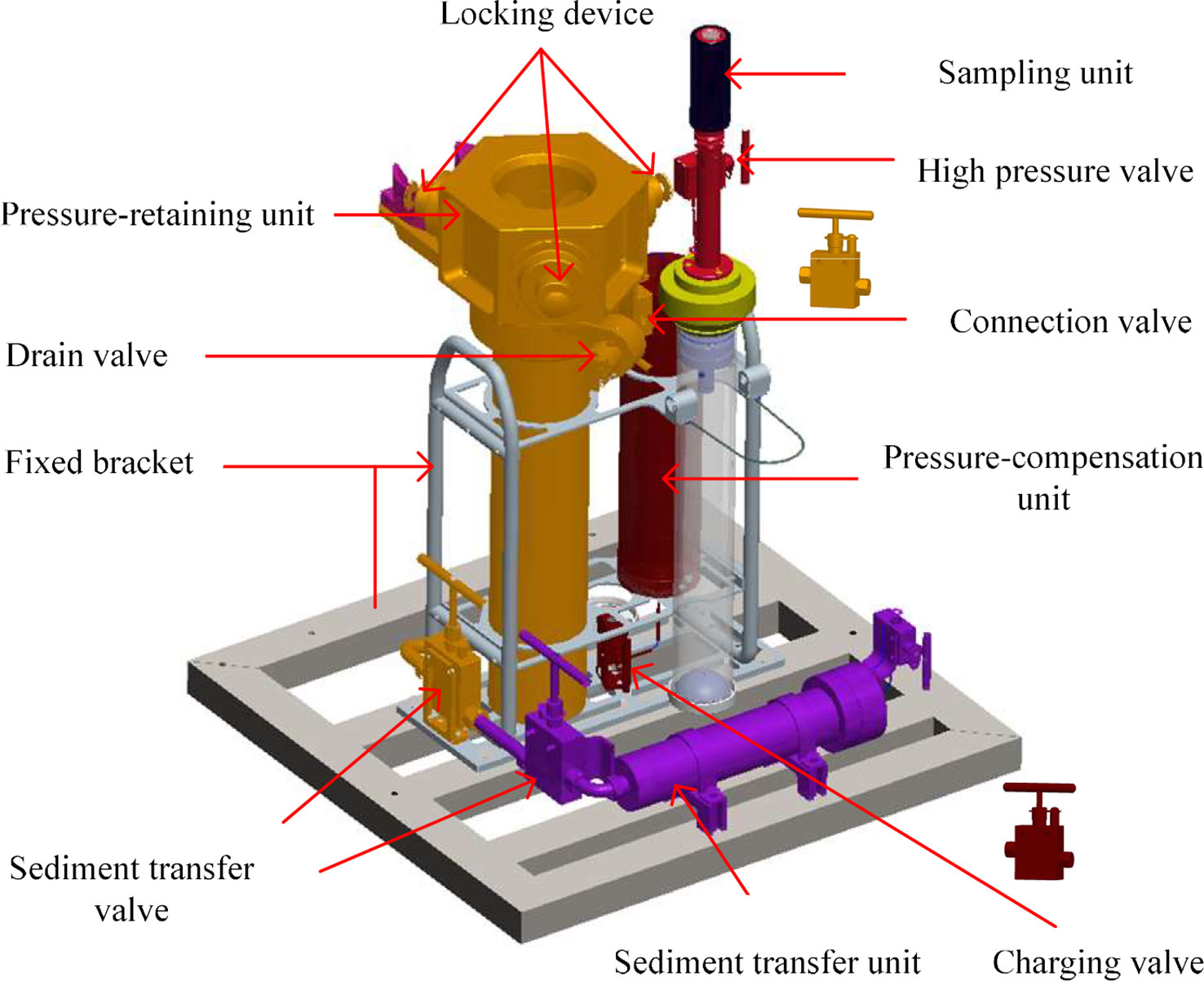
Figure 1 Structure scheme of the sediment sampler.
2.1.1 Sampling unit
The main function of the sampling unit is to collect deep-sea sediments. Its main components include of a sampling handle, a sealing element 1, a sampling tube assembly, sediment transfer pistons and sealing elements as shown in Figure 2. The sidewall at the end of the sampling tube is provided with a plurality of evenly distributed drain holes to facilitate the drainage. The outer side of the sampling tube is connected with sealing element 1 through threading. After the sampling is completed, the mechanical arm is used to grab the handle and put it into the pressure-retaining cylinder. The force from the lock spring enables the push-stop rod to lock the sealing element 1 of the sampling unit. At this time, the force form the support spring enables the sealing element 1 and the floating piston to be sealed.
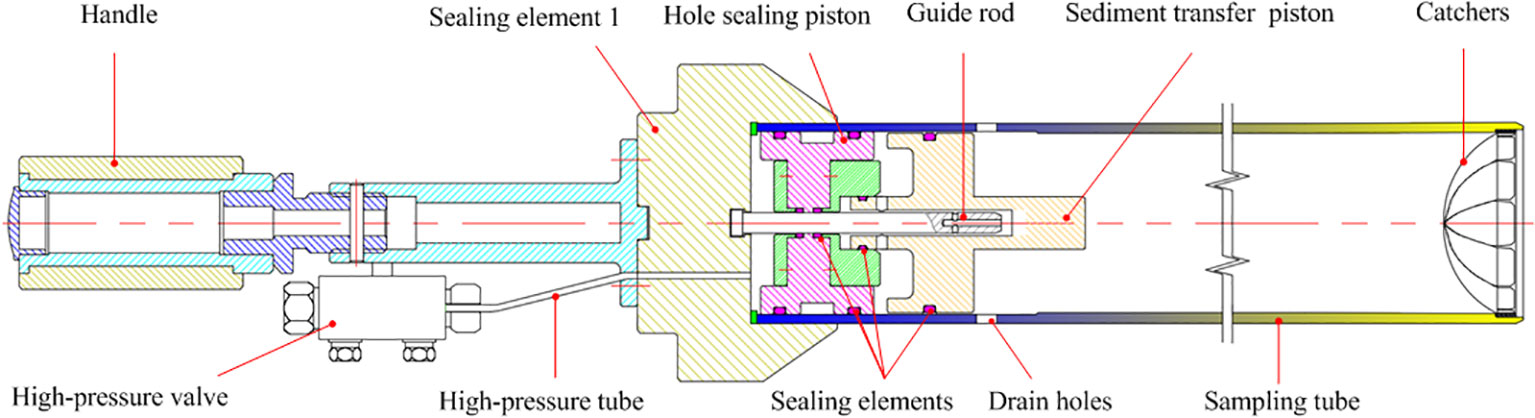
Figure 2 Structure scheme of the sampling unit.
2.1.2 Pressure-retaining unit
As can be seen from Figure 3, the pressure-retaining unit is mainly comprised of a pressure-retaining cylinder, lock springs, support springs, pull rods, push-stop rods, a sealing element 2, sealing rings, etc. A stepped hole is placed within the inner hole of the pressure-retaining cylinder, and four blind holes with a certain depth parallel to the axis of the cylinder were arranged on the stepped surface. Each blind hole is provided with a spring, and the sealing element 2 is arranged on it. A sealing ring is designed between the sealing element 2 and the pressure-retaining cylinder. The upper end of the pressure-retaining cylinder is spaced with three holes each of which is spaced with a push-stop rod respectively. The pull rod is assembled with a push-stop rod through threading. A cover is arranged on the sidewall of the pressure-retaining cylinder corresponding to the push-stop rod hole. A lock spring is spaced between the corresponding cover and the push-stop rod, and a sediment transfer interface is designed at the bottom of the pressure-retaining cylinder.
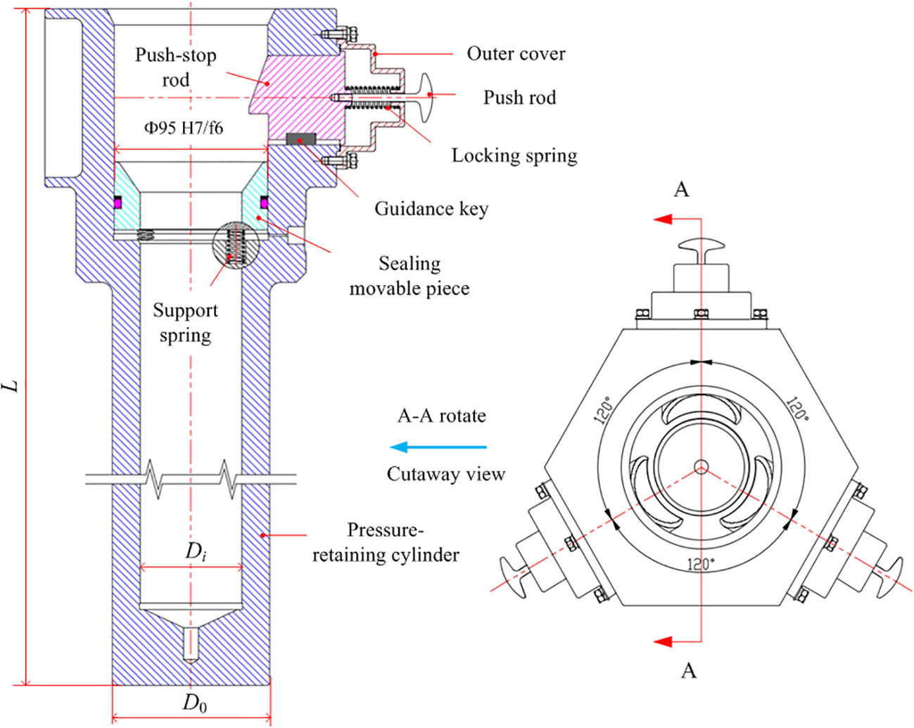
Figure 3 Structure scheme of the pressure-retaining unit.
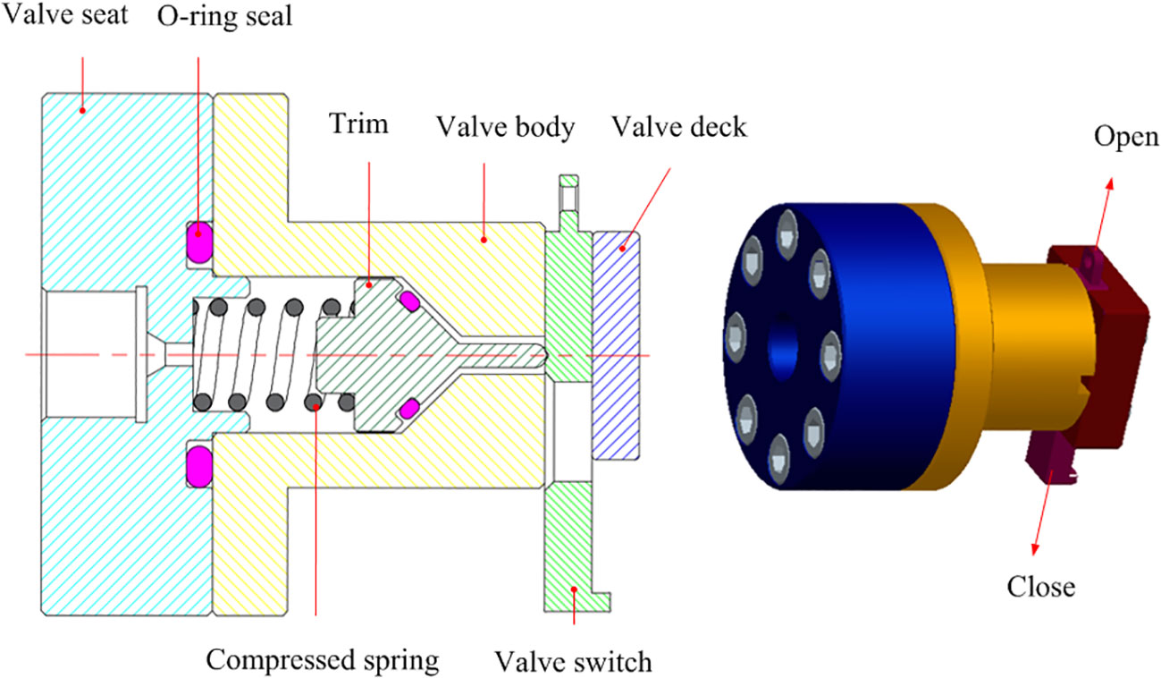
2.1.3 Drain valve
The drain valve is used to close the pressure pipe that connects the cylinder to the seawater outside. This drain valve allows the water in the cylinder to be discharged, relieving the internal pressure, which will ease the workload of the mechanical arm enabling it to press into the pressure-retaining cylinder. The valve includes a valve seat, valve trim, a valve body, a valve switch, a valve deck, and an O-ring seal. The drain valve has two main functions: first, while collecting samples through the sampling tube into the pressure-retaining cylinder, the valve switch is opened to discharge the seawater from the pressure-retaining cylinder, this ensures the initial seal between the sampling tube and the pressure-retaining cylinder. Secondly, after the sampling is completed, the valve switch is closed to guarantee the seal and retain the pressure in the pressure-retaining cylinder. The valve structure schematic is shown in Figure 4. The valve trim and the valve body are sealed using a combination of conical surface and an O-ring, and a compression spring is arranged between the valve trim and valve seat. When the valve switch positions itself in the position shown in the Figure 4, there is a gap between the valve trim and the conical surface of the valve body, and the drain valve is open. When the valve switch is pulled up, the ejector pin of the valve trim enters the valve switch hole driven by the compression spring, and the valve trim and the valve body are sealed. Subsequently, the drain valve is closed.
2.2 Working principle
The sediment sampler is mainly used to obtain pressure-retained sediment samples. After arriving at the sampling site, a mechanical arm is operated to collect samples and place them into the cylinder to be sealed and pressure-retained until returning to the submersible workboat. As shown in Figure 5, the working process is mainly divided into four stages: preparation, diving, sampling, and recovery:
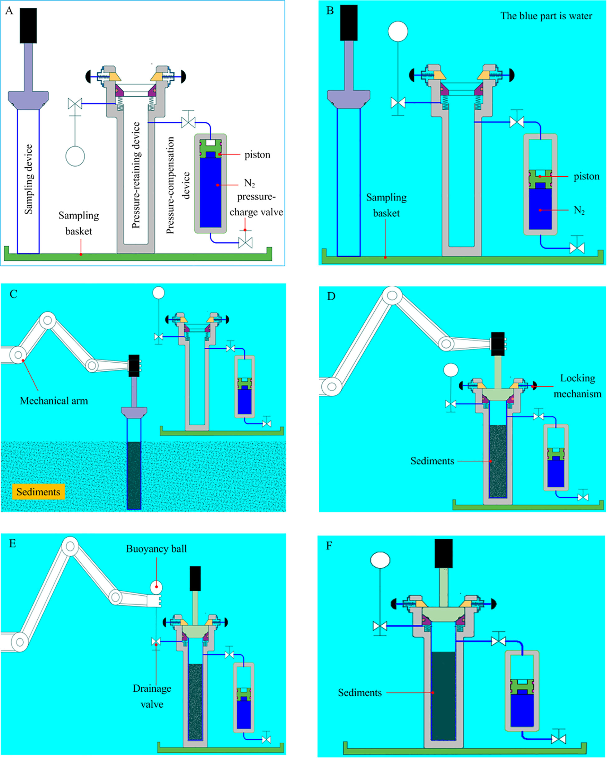
Figure 5 Working principle. (A) preparation stage of the sampler before diving, (B) the sampler dives with the submersible, (C) sampling at the sampling site, (D) sampling unit is locked after sampling, (E) drain valve is closed, and (F) recovery stage of the sampler.
Preparation stage: As shown in Figure 5A, before the sampler is launched with the submersible, and is fastened to the submersible’s tool basket, the sampling unit is fixed on the bracket, and the pressure-compensation unit is charged with a given pressure nitrogen. At this time, the piston is at the top of the cylinder. When the pressure reaches a set value, the inflation valve is closed to achieve pre-energy storage.
Diving stage: As shown in Figure 5B, after preparation, the sampler dives with the submersible. With the increase of diving depth, the pressure in the cylinder communicating with the outside seawater increases continuously. Under the action of the pressure difference, the compensation piston is moved downward, and the pressure levels at the two ends of the piston are kept in a balanced state, thus energy is continuously stored.
Sampling stage: Once the sampling site is reached, the mechanical arm is operated to grab the handle from the basket and move it to the seabed. The sampling tube is penetrated into the sediment at a given velocity (Figure 5C) and then retracted at a given velocity. Any sediment adhered on the outer wall of the sampling tube is removed with a mud scraper ring and then the sampler is inserted into the pressure-retaining cylinder until the sampling unit is locked in place (Figure 5D). Finally, the mechanical arm is used to close the drain valve and the sampler is sealed (Figure 5E).
Recovery stage: As shown in Figure 5F, during ascension to the sea surface, the sampler is tightly sealed. The pressure in the cylinder changes because of the change in the environmental temperature difference as well as external pressure, and the pressure-compensation unit releases the pressure accordingly to guarantee timely compensation of the pressure loss in the obtained samples.
3 Sampling kinematics model
As shown in Figure 6, considering the high pressure and complex environment experienced by the sampler under water, the sealing surface with O-ring sealing structure is adopted to guarantee pressure retaining under the ultra-high pressure. The seal between the floating piston and the cylinder adopts a combined sealing ring structure using an O-ring and retaining ring. The seal between the sampling unit and the floating piston adopts a combined sealing structure using a conical surface and fluoro rubber O-ring. After sampling is finished, the sampling unit is moved downwards by the external force until its sealing element 2 is attached to the conical surface of the floating piston, and the floating piston spring is compressed down. During this process, the seawater in the cylinder flows out of the cylinder through the drain valve driven by the pressure difference. A stress analysis of the penetration process of the sampling unit was conducted, as shown in Figure 6. F represents the pressing force when the sampling unit is pushed downward into the pressure-retaining unit. During this downward movement of the sealing element 2 and the floating piston, the friction between the floating piston and the cylinder wall is Ff, the elastic force of the floating piston spring is Ft, and the overall force of the internal sea water pressure acting on the whole sampling unit is P0S.
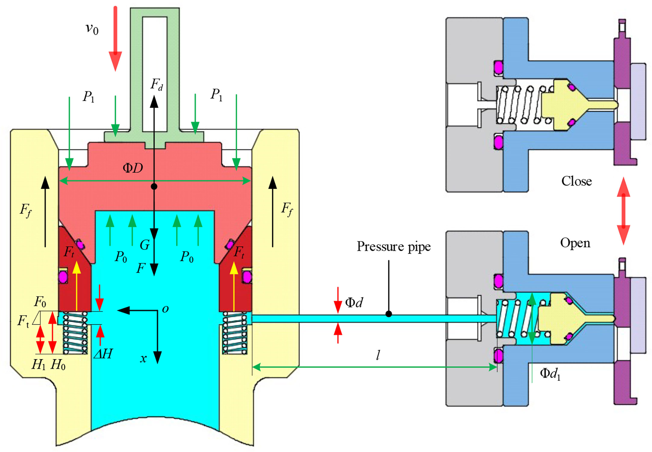
Figure 6 Stress analysis diagram of dynamic seal structure.
Assuming that the whole sampling unit moves downward at a uniform velocity under the pressing force, according to the force balance, there is:
where ΔP is the pressure difference between the inside and outside of the pressure-retaining unit, ΔP=P0-P1; S is the cross-sectional area of the upper surface of the sealing element 2; D is the outer diameter of sealing element 2; Ffis the friction force between gas-tight piece and the cylinder wall, which can be experiment ally obtained; Ftis the elastic force of the floating piston spring; k is the elastic coefficient of the spring, and G is the overall gravity.
When the sampling unit penetrates into the pressure-retaining cylinder, it is assumed that the seawater in the pressure-retaining cylinder will be discharged through the drain valve according to Bernoulli equation:
where P0 is the seawater pressure in the cylinder; ρ is the seawater density; v0 is the pressing velocity when operating the sampling unit; g is the acceleration of gravity; z0 is the position head of the seawater surface in the cylinder; z1 is the position head of the water outside outlet; P1 is the seawater pressure outside the cylinder; v1 is the seawater flow velocity the water outside the outlet; ΣΔhfis the total loss energy during seawater discharge; and ΣΔhjis total local loss energy during seawater discharge.
During the seawater discharge, Δhf is the loss energy along the way caused by overcoming the resistance, which is calculated as follows:
where l is the length of the pressure pipe; d is the inner diameter of the pressure pipe; and λ is the loss coefficient of the fluids along the pressure pipe, which is related to the Reynolds number and the roughness of the pressure pipe wall. The critical Reynolds number Rec is used as the criterion for judging laminar and turbulent flow regime, which is usually taken as Rec=2300.
When Re≤Rec, the seawater fluid flow within the pressure-retaining cylinder is laminar. The value of λ is only related to Re and has nothing to do with the pipe roughness, therefore λ as the loss coefficient along the flow path is a function of Reynolds number, calculated as:
When Rec≤Re ≤ 4000, the fluid flow in the pressure pipe is in the transition zone between laminar and turbulent flow. In actual practice, there are fewer Re number in this range, and the research within this range is limited. Hydraulic smoothness is adopted here as:
When Re>Rec, the area where the fluid flows in the pressure pipe is a hydraulic smooth area. The value of λ in this area is only dependent on Re and has nothing to do with the relative roughness, which can be expressed by the Blasius formula as:
where the value of λ is related to the flow state of the viscous fluid in the sampling tube, the inner diameter and the roughness of the inner wall of the sampling tube; and Re is the Reynolds number of the fluid, which can be expressed as:
where η is the kinematic viscosity of seawater and v is the flow velocity of seawater, and according to the fluid continuity equation, there is:
When seawater flows through abrupt boundaries, e.g., bends and drain valves, forces are generated that hinder its flow, thus causing local losses Δhj:
where ξ is the local resistance coefficient, which can be obtained by consulting relevant data.
(1) For the piston movement process (ΔH=H0~H1):Δhf1 is the loss along the path during the seawater discharge process:
(2) For the drainage process of the drain valve(l):Δhf2 is the loss along the path during the seawater discharge process:
According to Formulas (12) and (13), the total loss in the seawater discharge process is obtained as:
During the drainage process, local resistance mainly appears at the cross section of cylinder wall opening, the cross section between the hole and pressure pipe, and the cross section between the pressure pipe and drain valve guide holes. According to formula for calculating local loss, the local losses at each abrupt boundary during seawater discharge are obtained successively.
(1) When the seawater flows into the opening of the cylinder wall, the local loss coefficient is ξ1 = 0.5, which can be expressed as:
(2) Due to the design of the pressure pipe, seawater flows through bent sections, and the local loss coefficient of a 90° bend pipe is ξ2 = 0.132. The local loss in this process can be expressed as:
where n is the number of 90° bends.
(3) The seawater flows into the drain valve, which has a one-way valve structure, at which point the loss coefficient is ξ3 = 2, which can be expressed as:
According to equations (15)~(17), the total local loss from these main abrupt flow sections can be obtained as:
With the prerequisite of satisfying the structural design of the pressure-retaining unit, during the process of pressing, the relationship between pressing force(F2) and flow velocity(v0) is greatly influenced by flow resistance, which is mainly determined by the design and layout of the pressure pipes.
In order to ensure a smooth pressing process, the minimum pressing force(Fm) should be Fm≥F. The calculation parameters of the specific model are shown in Table 1

Table 1 Parameters of the kinematics model.
4 Results and discussion
Using the univariate method, the influence rules of pressure pipe length(l), pressure pipe inner diameter (d), and pressing velocity(v0) on pressing force are calculated and obtained to provide a theoretical reference for parameter design of the sampling structure.
Figure 7 shows the relationship between pressing force and pressing displacement under the condition that pressure pipe length(l) is 100 mm and pressure pipe inner diameter(d) is 2 mm. Clearly, the pressing force and the pressing displacement change linearly as pressing velocity changes, and the greater the pressing velocity, the greater the pressing force required. When the pressing velocity is 1 mm/s, the pressing force of the pressing process is within 100 N; but when the pressing velocity reaches 6 mm/s, the pressing force of the pressing process reaches 533 N. Field experiments have shown that the maximum pressing force that the mechanical arm can provide underwater is about 500 N. If the maximum pressing force is exceeded, the sampler will be unable to lock and seal the sampling unit, so it is very important that a reasonable pressing velocity is selected.
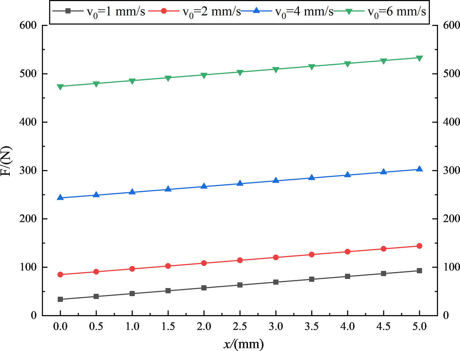
Figure 7 Influence of pressing displacement on pressing force.
The pressing velocity of the mechanical arm directly determines the pressing force. Figure 8 shows the relationship between the pressing force and pressing velocity (1~20 mm/s) when the pressure pipe is 100 mm in length and has an inner diameter of 2 mm. It is clear that the pressing force increases significantly with increasing pressing velocity, and the greater the pressing velocity, the larger the increase in pressing force. From the above analysis, the selection of an appropriate pressing velocity can effectively reduce the pressing force and ensure effective sealing during sampling operation. Generally, to make the operation of the mechanical arm more convenient, the pressing velocity should be as low as possible (usually 2 to 6 mm/s), while also guaranteeing that the pressing force is less than 500 N.
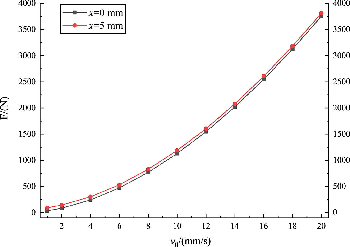
Figure 8 Influence of pressing velocity on pressing force.
Figures 9 and Figure 10 show the relationships between pressing force and the length and inner diameter of the pressure pipe at different displacements. As can be seen from Figure 9, the pressing force increases linearly with increasing length of the pressure pipe, and the degree of increase is basically the same among displacements. This further demonstrates that the length of the pressure pipe should be as short as possible when designing the drainage structure of the sampler. This is because the shorter the pressure pipe length, the smaller the loss energy along the path(Δhj). In this way, the pressing force can be reduced to facilitate sampling and sealing.

Figure 9 Influence of pressure pipe length on pressing force.
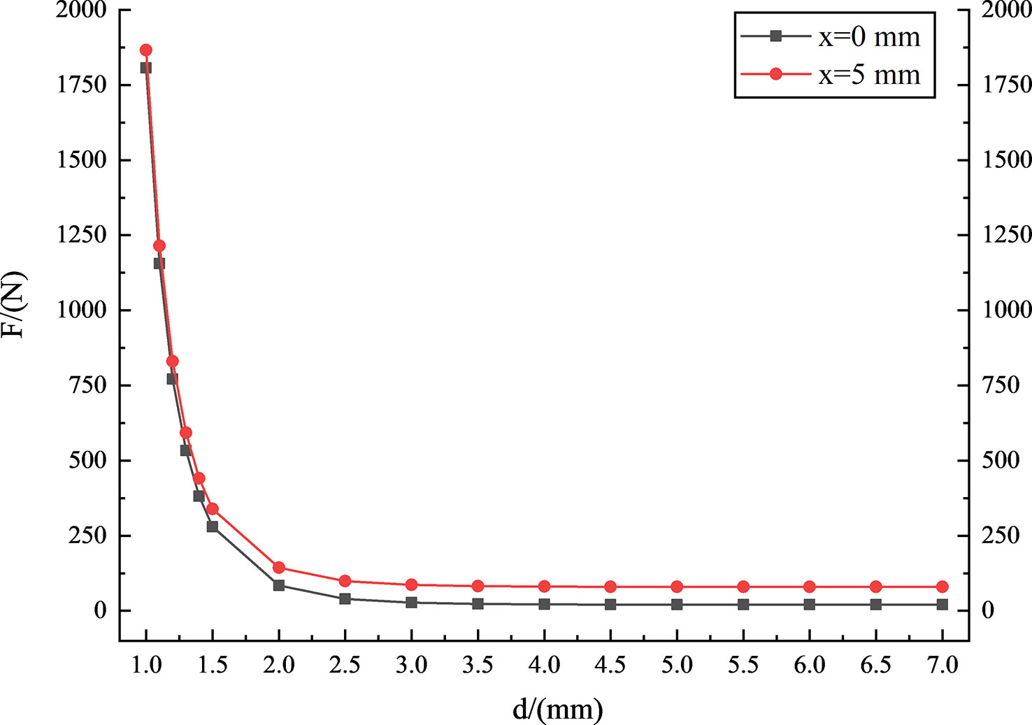
Figure 10 Influence of inner diameter of pressure pipe on pressing force.
As shown in Figure 10, when the mechanical arm presses at a constant velocity of 2 mm/s, the inner diameter of the pressure pipe has a strong influence on the pressing force when the diameter (d) of the pressure pipe is less than 2 mm. However, when the diameter(d)of the pressure pipe is greater than 2 mm, the pressing force is not greatly affected by the inner diameter of the pressure pipe. For example, at the end of the pressing displacement when x=5 mm, when the inner diameter increases from 1 mm to 2 mm, the pressing force decreases by 92.3%; but when the inner diameter increases from 2 mm to 3 mm, the pressing force decreases by 44.8%, which is about 0.5 that of the former. Therefore, the design of the inner diameter of the pressure pipe is of great importance because it directly determines the pressing force required from the mechanical arm.
5 Sea trial
The sampler was mounted on the HOV Fendouzhe(Striver) in the West Philippine Basin during cruise TS-21 from August to October 2021, which was organized by the Institute of Deep-sea Science and Engineering of Chinese Academy of Sciences. The sampler was deployed 4 times at the water depth of 7700 m in the West Philippine Basin. Figure 11A shows that the sampler was installed and fixed in the tool basket of the submersible after all preparations and inspections were complete. Figure 11B shows the submersible robot being operated by the pilot to carry out sampling operations after the sampler reached the sampling site. Figure 12A shows the final pressure of the samples in the sampler after ascending to the surface and Figures 12B-D shows the sediment samples obtained during the sea trial.
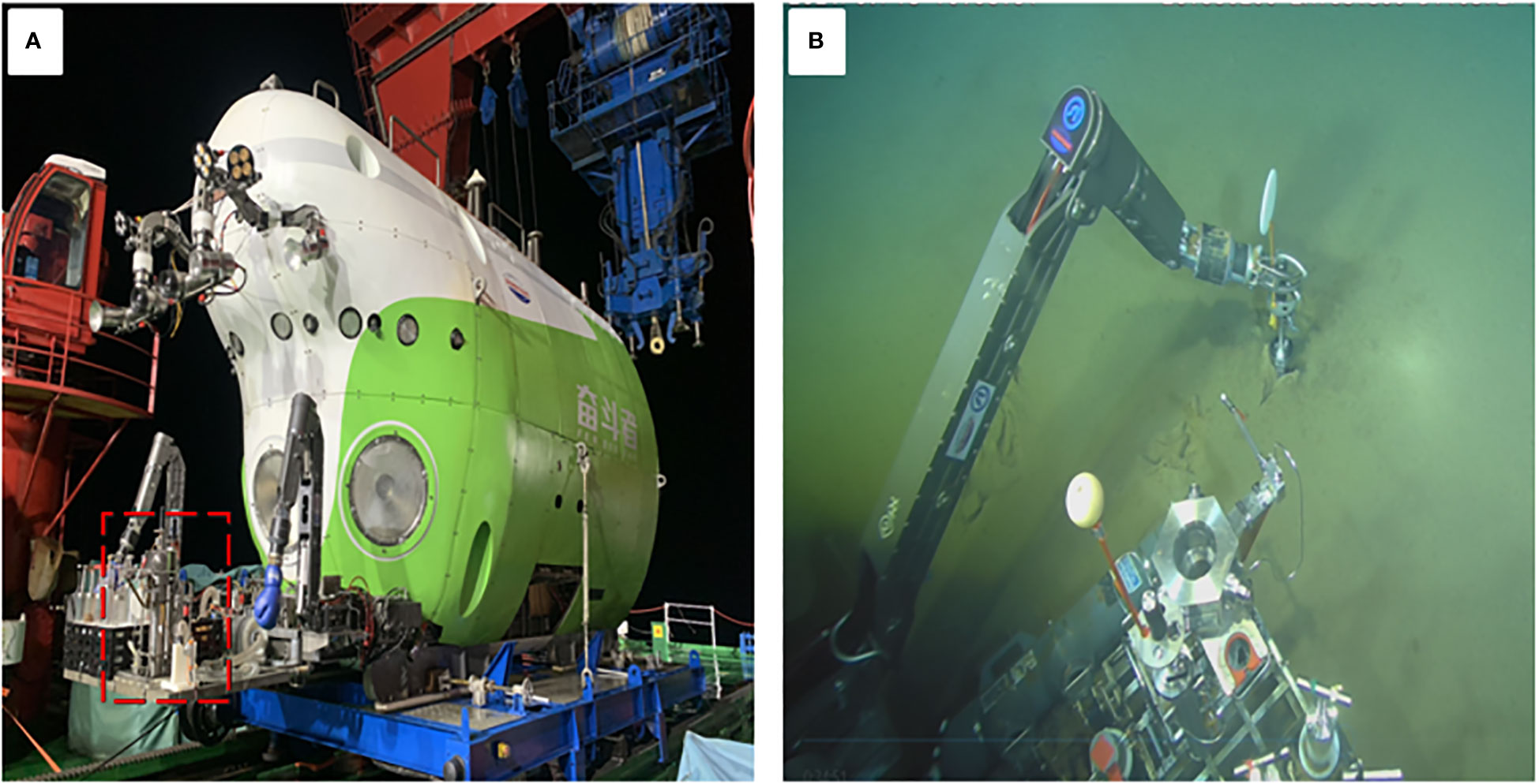
Figure 11 The scene of the sea trial, (A) the sampler was installed and fixed in the tool basket, and (B) the sampling operations after the sampler reached the sampling site.
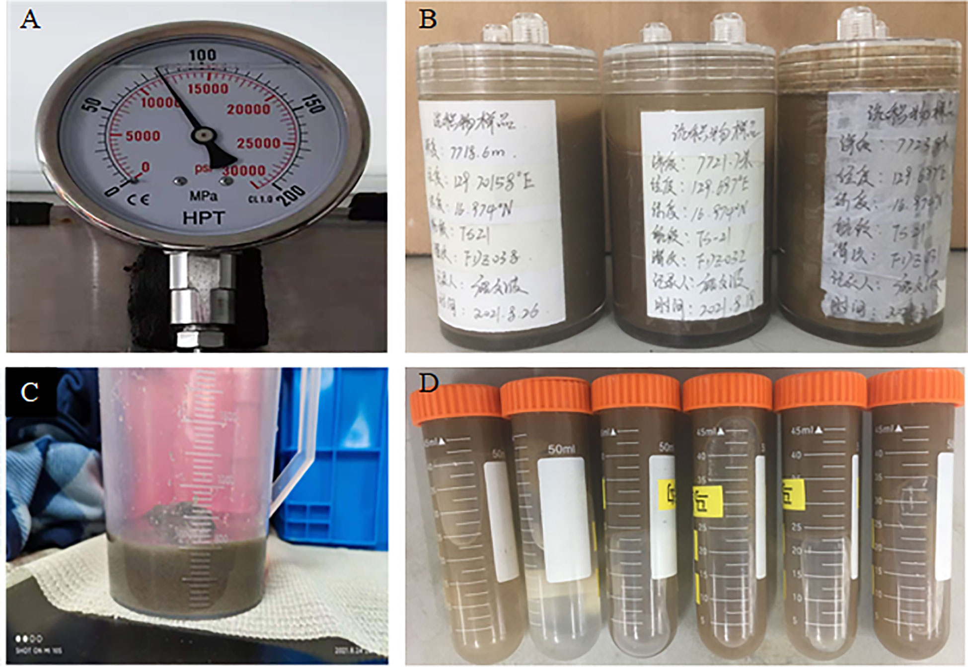
Figure 12 Sediment sample obtained, (A) the final pressure of the samples in the sampler, (B–D) the sediment samples obtained during the sea trial.
As shown in Table 2, pressure-retained sediment samples were obtained in the third and fourth operational trials. The retained pressures were 74.5MPa and 81MPa, respectively, in which the respective pressure changes were -6% and +3%. The results of the fourth sampling show that the pressure of the sample was greater than the in-situ pressure, which was due to gas expansion caused by the temperature increase as the submersible rose to the sea surface. Upon completion, this sea trial represented the first time that China has obtained high-quality pressure-retained sediment samples from an abyssal environment at a depth of more than 7,000 m.

Table 2 Sea trial results.
6 Conclusion
(1)The proposed sampler can be mounted on a submersible and used to obtain samples that are pressure-retained and sealed using a single mechanical arm. In this way, in-site sediment samples can be successfully obtained for scientific investigations interested in seabed geological resource exploration, microbial communities, chemistry, and life evolution.
(2)The sampler was tested in a field sea trial in the high seas of the Philippine Sea, and sediment samples with high pressure-retaining rates were successfully collected from the seabed at a water depth of 7700 m. The pressure change of the collected samples was within ±6%.
(3) The novel pressure-retaining sediment sampler designed in this study is compact in structure and light in weight, making it suitable for operation by an ROV or HOV mechanical arm in the abyssal environment. This prototype provides new insight into the design of portable deep-sea samplers. Similar novel samplers will likely be widely used in the deep-sea field for the investigation of life evolution and abyssal environment.
(4) In the future, more functions will be added to the sampler. For example, an temperature-retaining function to control the temperature; a multi-functional in-situ test instrument to conduct in-situ tests on the end resistance, friction force, pore water pressure, and CT scanning technology for in-situ sample analysis; and chemical or physical analysis equipment for sediment.
Data availability statement
The original contributions presented in the study are included in the article/Supplementary Material. Further inquiries can be directed to the corresponding author.
Author contributions
SH: software, data curation, writing original draft and visualization. SQ: data curation, writing original draft and visualization. WT: conceptualization, methodology, writing review, editing and validation. YP: software, visualization, investigation. YJ: data curation, visualization and investigation. YP: supervision, writing review and editing. All authors contributed to the article and approved the submitted version.
Funding
This work is supported by National Key R&D Program of China (Grant No. 2016YFC0300502) entitled “Development of the Gas-tight Sampler for full-ocean-depth sediments”. This work is supported by the National Natural Science Foundation of China (Grant No.51705145) and Natural Science Foundation of Hunan Province of China (Grant No.2019JJ50182).This work is also supported by Scientific Research Fund of Hunan Provincial Education Department (Grant No.22B0867).
Acknowledgments
The author sincerely thanks to Professor YP, who is currently a professor of Hunan University of Science and technology for his critical discussion and reading during manuscript preparation.
Conflict of interest
The authors declare that the research was conducted in the absence of any commercial or financial relationships that could be construed as a potential conflict of interest.
Publisher’s note
All claims expressed in this article are solely those of the authors and do not necessarily represent those of their affiliated organizations, or those of the publisher, the editors and the reviewers. Any product that may be evaluated in this article, or claim that may be made by its manufacturer, is not guaranteed or endorsed by the publisher.
References
Abegg F., Hohnberg H.-J., Pape T., Bohrmann G., Freitag J. (2008). Development and application of pressure-core-sampling systems for the investigation of gas-hydrate-bearing sediments. Deep Sea Res. Part I: Oceanographic Res. Papers 55, 1590–1599. doi: 10.1016/j.dsr.2008.06.006
Amann H., Hohnberg H.-J., Reinelt R. (1997). HYACE–a novel autoclave coring equipment for systematic offshore gashydrate sampling. Deutsche Wissenschaftliche Gesellschaft für Erdgas und Kohlee.V. (DGMK) 9706, 37–49.
Case D. H., Ijiri A., Morono Y., Tavormina P., Orphan V. J., Inagaki F. (2018). Aerobic and anaerobic methanotrophic communities associated with methane hydrates exposed on the seafloor: A high-pressure sampling and stable isotope-incubation experiment. Frontier Microbiol. 8, 25–69. doi: 10.3389/fmicb.2017.02569
Chen J., Huang Y., Lin Y., Zhou P., Fang Y., Le X., et al. (2020). A novel sediment pressure sampling device carried by a hadal-rated lander. J. Mar. Sci. Eng. 8 (11), 839. doi: 10.3390/jmse8110839
Dickens G. R., Paull C. R., Wallace P. (1997). Direct measurement of in situ methane quantities in a large gas-hydrate reservoir. Nature 385, 426–428. doi: 10.1038/385426a0
Drazen J. C., Yeh J. (2012). Respiration of four species of deep-sea demersal fishes measured in situ in the eastern north pacific. Deep Sea Res. Part I: Oceanographic Res. Papers 60, 1–6. doi: 10.1016/j.dsr.2011.09.007
Eric M., Javier E., Nuno G. (2012). Quantifying diffuse and discrete venting at the tour Eiffel vent site, lucky strike hydrothermal field. Geochem. Geophys. Geosystems 13, 4. doi: 10.1029/2011GC003990
Francis T. J. G., Lee Y. D. E. (2000). Determination of In-situ sediment shear strength from advanced piston corer pullout forces. Mar. Georesources Geotech. 18 (4), 295–314. doi: 10.1080/10641190009353797
Garel M., Bonin P., Martini S., Guasco S., Roumagnac M., Bhairy N., et al. (2019). Pressure-retaining sampler and high-pressure systems to study deep-sea microbes under in situ conditions. Front. Microbiol. 10, 453. doi: 10.3389/fmicb.2019.00453
Guo J., Wang Y., Wang W., Ren X., Zhou P., Fang Y., et al. (2022). Pressure-retaining sampler for sediment including overlying water based on heavy duty ROV-jellyfish. Appl. Ocean Res. 128, 103354. doi: 10.1016/j.apor.2022.103354
Huang H. C., Huang L., Ye W., Wu S., Yang C., Chen Y., et al. (2018). Optimizing preloading pressure of pre-charged gas for isobaric gas-tight hydrothermal samplers. J. Pressure Vessel Technol. 140 (2), 021201. doi: 10.1115/1.4038901
Huang Z. H., Liu S. J., Jin B. (2006). Accumulator-based deep-sea microbe gas-tight sampling technique. China Ocean Eng. 20 (2), 335–342.
Kawasaki M., Umezu S., Yasuda M. (2006). Pressure temperature core sampler (PTCS). J. Jpn. Assoc. Pet. Technol. 71, 139–147. doi: 10.3720/japt.71.139
Kim S. J., Kato C. (2010). “Sampling, isolation, cultivation, and characterization of piezophilic microbes,” in Handbook of hydrocarbon and lipid microbiology. Ed. Timmis K. N. (Berlin Heidelberg: Springer-Verlag), 3869–3881.
Koyama S., Miwa T., Horii M., Ishikawa Y., Horikoshi K., Aizawa M. (2002). Pressure-stat aquarium system designed for capturing and maintaining deep-sea organisms. Deep Sea Res. Part I: Oceanographic Res. Papers 49 (11), 2095–2102. doi: 10.1016/S0967-0637(02)00098-5
Kubo Y., Mizuguchi Y., Inagaki F., Yamamoto K. (2014). A new hybrid pressure-coring system for the drilling vessel chikyu. Sci. Drilling 17, 37–43. doi: 10.5194/sd-17-37-2014
Kvenvolden K. A., Barnard L. A., Cameron D. H. (1982). Pressure core barrel: Application to the study of gas hydrates, deep Sea drilling project site 533, leg 76; initial reports DSDP (Washington, DC, USA: Texas A&M), 367–375.
Lu D. Q., Ding Z., Li D., Liu B. (2019). Studies and applications of cobalt-rich crust core samplers mounted on “Jiao long”. Manned Submersibles China Mechanical Eng. 30, 5603–5607.
Nunoura T., Takaki Y., Hirai M., Shimamura S., Makabe A., Koide O., et al. (2015). Hadal biosphere: Insight into the microbial ecosystem in the deepest ocean on earth. Proc.Natl. Acad. Sci. U.S.A. 112, E1230–E1236. doi: 10.1073/pnas.1421816112
Ritchie H., Jamieson A. J., Piertney S. B. (2017). Population genetic structure of two congeneric deep-sea amphipod species from geographically isolated hadal zone in the pacific ocean. Deep-Sea Res. I 119, 50–57. doi: 10.1016/j.dsr.2016.11.006
Schultheiss P. J., Holland M., Humphrey G. (2009). Wire-line coring and analysis under Pressure: Recent use and future developments of the HYACINTH system. Sci. Drilling 2009 (7), 44–50. doi: 10.2204/iodp.sd.7.07.2009
Keywords: ocean depth, sediment, mechanical design, pressure-retaining sampler, kinematics model, sea trial
Citation: He S, Qiu S, Tang W, Peng Y and Jin Y (2023) A novel submersible-mounted sediment pressure-retaining sampler at full ocean depth. Front. Mar. Sci. 10:1154269. doi: 10.3389/fmars.2023.1154269
Received: 30 January 2023; Accepted: 22 February 2023;
Published: 09 March 2023.
Edited by:
Shaowei Zhang, Institute of Deep-Sea Science and Engineering, Chinese Academy of Sciences, Sanya, ChinaReviewed by:
Rongwang Zhang, State Key Laboratory of Tropical Oceanography, South China Sea Institute of Oceanology, Chinese Academy of Sciences, Guangzhou, ChinaDoug Bartlett, University of California, San Diego, United States
Copyright © 2023 He, Qiu, Tang, Peng and Jin. This is an open-access article distributed under the terms of the Creative Commons Attribution License (CC BY). The use, distribution or reproduction in other forums is permitted, provided the original author(s) and the copyright owner(s) are credited and that the original publication in this journal is cited, in accordance with accepted academic practice. No use, distribution or reproduction is permitted which does not comply with these terms.
*Correspondence: Shudong He, aGVzaHVkb25nLjE5ODdAMTYzLmNvbQ==