 Changqing Jiang
 Ould el Moctar
 Guiyong Zhang2
95% of researchers rate our articles as excellent or good
Learn more about the work of our research integrity team to safeguard the quality of each article we publish.
Find out more
ORIGINAL RESEARCH article
Front. Mar. Sci. , 23 February 2023
Sec. Ocean Solutions
Volume 10 - 2023 | https://doi.org/10.3389/fmars.2023.1138235
This article is part of the Research Topic Advances in Multi-use Floating Islands View all 7 articles
Within the Space@Sea project, a multi-use floating concept was proposed by following the analogy of standardization to enlarge a floating platform using a multitude of smaller structures. An operability analysis must be performed to identify its seakeeping criteria and how the criteria limit its functionality. A two-step strategy is proposed to calculate the responses of the target floating concept in head waves, where nonlinearities of the mooring lines and mechanical joints are taken into account. The weakly nonlinear time-domain procedure relies on a diffraction-radiation model in the frequency domain. The motions of floating bodies are solved in the time domain, in which nonlinear Froude-Krylov and hydrostatic forces are estimated under instantaneous incident wave surface. Multibody interactions are resolved under consideration of catenary mooring lines and hinged joints. Wave-induced motions and loads are expressed in terms of transfer function for determining the limiting criteria, including the translational and rotational motions velocities and accelerations; relative motions, velocities and accelerations between module floaters; mooring tensions; as well as hinge forces. Assessments are carried out for various sea conditions against the prescribed values, for the chosen criteria, to address safety issues due to sever platform responses. Different operational requirements for trained workers and untrained passengers of motions and accelerations are taken into consideration. Results show that rotational motions have a significant influence on the platform’s seakeeping performance. Nevertheless, the root mean square (RMS) value of vertical acceleration dominates the comfort of persons onboard, defining the final limiting criterion of the entire platform.
The majority of the world’s population lives in coastal areas where space has always been at a premium because available land space is limited. On other hand, global sea levels is rising with global warming, waterfronts are reclaiming and changing the utilization of large parts of existing land spaces. With the increasing need for affordable deck space at sea, various concepts of man-made islands were proposed (Kondo and Vadus, 1991). For shallow waters, a land reclamation technology may be used to creating or extending sandy islands, whose applications, however, are limited by water depths. Floating concepts have the advantage of being suitable for deeper waters, and they can be relocated if needed. In this context, concepts for very large floating structure (VLFSs) were designed (Suzuki et al., 2006). These VLFSs could be used in many ways, for example, as platforms for the development of marine resources, oil and gas exploration, offshore tourism, or fish farming (Souravlias et al., 2020). A review of various concepts of VLFS for coastal and offshore used was documented in Lamas-Pardo et al. (2015). The barriers for multi-use of artificial floating islands in the rules and regulations were identified by Flikkema et al. (2021b). Within the Space@Sea project, a standardized floating concept was developed, and modularity was one of the key elements. By following the analogy of standardization to enlarge a floating structure using a multitude of smaller structures, this project intended to significantly reduce building and installation costs, meanwhile bringing strong flexibility but low environmental impact (Tamis et al., 2021). For comprehensive overviews of this project, see Flikkema and Waals (2019) and Flikkema et al. (2021a).
In contrast to conventional VLFSs of continuous concept, modular floating structures (MFSs) can be described as an array of relatively small floating modules, assembled to a considerable large-scale platform. For MFSs utilized by the general public, obligations in safety and serviceability require that limiting criteria must be applied to their seakeeping responses as a result of human factors and environmental conditions. Obeng et al. (2022) stated that environmental factors also influence the human factor that contributes to marine accidents. In addition, a more thorough assessment into mission oriented seakeeping performances is motivated by a tendency towards increasingly rough weather conditions triggered by climate change (Young and Ribal, 2019). Guidelines and regulations for ship motions regarding structural integrity, safe operation of machinery, and human comfort are available for merchant vessels, passenger ships, and offshore platforms (Vibration, 1984). Nevertheless, in most cases no limiting values are given due to the dependency of the hull/floater and machinery design. Mainly for the human comfort in terms of vibration, an extensive overview of existing norms and standards regulating the assessment of human exposure to motions in offshore environments can be found in Schwarzkopf et al. (2018). Their extensive literature research identified the need for a consistent assessment method in combination with threshold values for floating structures. For a standing person to maintain postural stability, the allowable dynamic responses of a floating structure have to be specified. Freeman et al. (2017) summarized the current understanding of postural stability and reviewed the considered postural stability in design. The summarized information was categorized into a set of motion limit criteria that were compared with new experimental results of a floating pontoon. In general, vertical accelerations and relative motions between ship hull and wave are identified as critical for favorable seakeeping performance (Faltinsen, 1993). For ships, parametric study (Beukelman and Huijser, 1977) concluded that seakeeping performance appeared to be dominated by ship length, while the forebody section shape and the block coefficient indicated only minor influences. Gutsch et al. (2020) explored the influence of designs parameters on seakeeping performance for offshore vessels, where a novel parameter named the operability robustness index (ORI) was used. Their results showed that for certain vessel parameters the performance of a larger vessel is not better than that of a smaller vessel. For seakeeping performance criteria of offshore vessels, see also Sariöz and Narli (2005); Tello et al. (2011); Brans et al. (2021); Iqbal et al. (2022).
To assess the seakeeping performances of a multibody platform in waves, various methods, generally categorized as linear, weakly nonlinear and fully nonlinear, have been developed. In reference to linear frequency-domain methods, an amount of studies have been carried out to analyze multibody hydrodynamics (van Oortmerssen, 1979; Løken, 1981; Kodan, 1984). It is worth noting that the coupling between floating bodies were not considered within these early works, as the motion equation of each body was individually solved in the frequency domain. Later on, a linear frequency-domain technique using a mode expansion method to calculate the motions of simply connected floating bodies was introduced by Newman (1994). However, this approach was primarily aimed for solving simply linked bodies, where the system can be regarded as a single deformable body. Similar works can also be found in Lee and Newman (2000); Fu et al. (2007); Taghipour and Moan (2008); Gao et al. (2011). It must be noted that, generally within these approaches, the linear potential-flow theory in frequency domain is adopted, and the connecting joints are treated as independent six degrees-of-freedom linear springs or as a discretized stiffness matrix. Numerous works based on these simplified methods are not substantial discussed herein.
During the last two decades, analyses into ship and offshore structure in time domain have significantly increased, replacing frequency-domain analyses to some extent. This is driven by the strong demand for building very large ships and offshore structures, whose nonlinear motions and structural loads are required to be solved in the time domain (ITTC, 2008). Typical problems include nonlinear wave excitation, the resultant motion, structural loads, green water, slamming and whipping, hydroelasticity, sloshing and coupling with ship motion. Partial (weakly) nonlinear methods based on potential flow have become standard tools for predicting hydrodynamic performance of ships and offshore structures. Such methods are developed with some degrees of linearization in hydrodynamics solutions, but the equations of motion and loads include nonlinear terms (Fonseca and Guedes Soares, 2002). Despite multibody interactions having been widely studied using these approaches, most of them focused on the hydrodynamics of side-by-side vessels (Huijsmans et al., 2001; Buchner et al., 2004; Kashiwagi et al., 2005; Fournier et al., 2006; Pauw et al., 2007; Huang et al., 2018; Li, 2020). For the hydrodynamics of multibody offshore platforms, additional attentions must be paid to their mooring and mechanical coupling systems. For instance, the hydrodynamic interaction and mechanical coupling effects of two floating platforms connected by elastic lines were investigated by Koo and Kim (2005) using a time-domain coupled dynamics analysis program. Particular attention was paid to the contribution of off-diagonal hydrodynamic interaction terms on the relative motions during side-by-side offloading operation. Additionally, the effects of mechanical coupling systems between multiple bodies are also involved in the wave energy sector. Peng et al. (2020) performed time-domain simulations of a hinged-type wave energy converter (WEC) in regular waves, in which the considered WEC unit consisted of four modules connected by rigid truss structures. For more studies dealing with mechanical connections between multiple bodies, see Diamantoulaki and Angelides (2010); Rogne (2014); Zhu et al. (2017); Ghesmi et al. (2019).
Apart from the multibody interactions, it is recognized that nonlinear effects are also important for MFSs, which cannot be neglected in the hydrodynamic calculations of design wave loads. Even so, for strong nonlinear conditions, partial nonlinear methods are challenging to fully reproduce the hydrodynamic process of wave-structure interactions (Jiang et al., 2022a). In this content, fully nonlinear potential-flow solutions have been used in the literature. Using a fully nonlinear potential-flow model, Feng and Bai (2017) studied the hydrodynamic performance of two freely floating or interconnected barges, where the hydrodynamic forces were indirectly calculated through an auxiliary function approach and the connection constraints were mathematically represented by a constraint matrix. Simulations were performed for waves with different steepness and the nonlinear effect was highlighted by decomposing the higher harmonic components of nonlinear responses. Beck (1996); Scorpio et al. (1996) and Subramani (1998), representing the hulls and free-surface boundaries via desingularized Rankine sources, computed nonlinear ship motions in an ideal fluid using the Euler–Lagrange method. Such a method was then extended and applied to ship-ship interaction problems (von Graefe et al., 2015). Nevertheless, to capture the nonlinearities of viscous and/or complex free-surface flows, high-fidelity viscous-flow solvers are the preferred choice (Jiang, 2021).Computational fluid dynamics (CFD) has been commonly applied in wave-structure interaction (WSI) problems based on generally two approaches: Eulerian (mesh-based) and Lagrangian (mesh-free) methods. In terms of the applications of mesh-based methods for multibody hydrodynamics, see Seithe and el Moctar (2019); Jiang et al. (2022c); Jiang et al. (2022d); Jiang and el Moctar (2023), where wave-induced motions and loads on articulated multibody offshore platforms were numerically analyzed. Regarding mesh-free approaches, Moreno et al. (2020) analyzed the response of a multi-float wave energy converter M4 in focused waves via a smoothed particle hydrodynamics (SPH) solver, where complex multi-floats were coupled with mechanical constraint and mooring.
Our literature review shows that the influence of environmental conditions on single body motions (e.g., ships) has been a research topic in the past decades and is relatively well understood. Nevertheless, the researches on articulated multibody floating offshore systems are very limited and MFSs with more than two bodies have hardly been considered in the literature. Moreover, seakeeping performances of MFSs are highly dependent on their applications and functionalities. Currently no design standards exist defining their allowable limits. The primary objective of this work is to systematically analyze the operability of a moored and articulated multibody floating platform in head seas, where mooring and connection induced nonlinearities are taken into account. The considered platform consists of fifty floating bodies, articulated by hinged joints and positioned using catenary mooring lines. For such a multibody system with interconnections, its complexity lies in not only the multibody hydrodynamics but also the coupled multibody dynamics. Moreover, nonlinear effects of mooring and connection systems, as well as incident waves need to be considered. To define the limiting criteria in hydrodynamic responses, a two-step strategy is proposed to calculate the responses of the target floating concept in waves. The weakly nonlinear time-domain procedure relies on a diffraction-radiation model in the frequency domain. The motions of floating bodies are solved in the time domain, in which nonlinear Froude-Krylov and hydrostatic forces are estimated under instantaneous incident wave surface. Multibody interactions are resolved under consideration of catenary mooring lines and hinged joints. The objective of this work is to define what the environmental criteria should be, and how the criteria limit the functionality of the target floating concept. We dispense with determining the multibody hydrodynamics of considered platform using a fully nonlinear approach (e.g., CFD calculations), as numerical problems still exist and the computational effort is also huge. Fully nonlinear solutions are still under development and they are challenging for simulating such a floating platform with fifty bodies in waves.
We employed the commercial software package AQWA (ANSYS, 2016), a weakly nonlinear potential-flow solver, for our computations. Specifically, we used two packages from its kernel, namely, the hydrodynamic diffraction module and the hydrodynamic response module, which enabled idealizing coupled articulated connections between bodies. The diffraction package computed the primary hydrodynamic variables required for complex motion and response analyses by solving the Green function for irrotational flow based on a boundary element panel method in the frequency domain. The use of Green singularities permits the automatic satisfaction of both the free-surface boundary condition and the radiation condition at infinity, allowing for the discretization with panels of the body surface only. The response package performed the dynamic analysis in the time domain by deriving the impulsive response from the diffraction module and solving the equation of motion by means of the convolution integration method., where nonlinear Froude-Krylov and hydrostatic forces were estimated under instantaneous incident wave surface. Second-order wave loads (e.g., slowing varying drift forces) were included, based on the full set of quadratic transfer functions (QTFs). The articulated hinge between floating bodies was modeled by adding kinematic constraints to the equations of motion, using a library of predefined coupling types. The forces and moments in these articulated connectors were determined by computing sectional loads at the articulation section. Right-handed orthogonal coordinate systems describe the motions of floating modules in waves, as depicted in Figure 1. Coordinate system o-xyz describes a global system and coordinate systems oi-xiyizi are the local systems fixed to modules and joints. The global coordinate system coincides with the undisturbed free surface, with its x-axis pointing in the direction of the stern of a module and its z-axis pointing vertically upward. An articulated one degree-of-freedom hinge joint connected the adjacent floating modules. These joints did not permit relative translation, but allowed relative rotations between adjacent modules. The joints were located on the calm waterline, with their axes yj parallel to global coordinate the y.
Figure 1 Coordinate systems used to describe structure motions.
For a flow assumed to be incompressible, inviscid and irrotational, its velocity potential satisfies the Laplace equation everywhere in the fluid domain:
The unsteady linear potential for a sinusoidal wave excitation with frequency ω is expressed as:
where ϕI (x,y,z) is the incident wave potential; ϕD (x,y,z), the diffraction potential; ξj, the body motions in each degree of freedom; and ϕj, the radiation potentials. The incident wave potential, in deep water, is given as follows:
where ζa is wave amplitude, k is wave number and β is wave heading. The total unsteady potential has to be satisfied in the fluid domain, on the free surface, on the submerged body surface, on the sea bed and, for the far-field radiation condition, at infinity. The free-surface condition is satisfied:
The boundary conditions on the seabed (at depth d) and at the wetted body surface are given as:
where nk,j is the unit normal vector component corresponding to the motions of bodyk. At infinity, the generalized wave disturbance must approach zero, i.e., the radiation condition:
where R denotes the distance from the oscillating body, and C the phase speed of the radiating waves. The hydrodynamic pressure on a body surface is calculated using Bernoulli’s equation:
where p is the pressure, ρ is water density, g is acceleration of gravity. The wave exciting force consists of the incident and diffracted part and the radiated part . Integrating the pressure on a body’s surface obtains in the incident and diffracted parts:
The radiated part is then expressed as follows:
where Tk,ij = ω2Ak,ij−iωBk,ij. Terms Ak,ij and Bk,ij are the added mass and damping coefficients, respectively:
Choosing the ratio of wave amplitude to wave length as the smallness parameter ϵ, the perturbation approach is employed to describe the fluid potential, wave elevation and the position of a point on structure, respectively:
where the superscript (0) denotes the static values, and (1) and (2) indicate the first- and second-order variations with respect to the perturbation parameter ϵ. Similarly, the fluid pressure becomes:
Based on Bernoulli’s equation in Eq. 8 and the fluid potential in Eq. 12, the hydrostatic pressure can be determined:
The first-order pressure is given as:
Similarly, the second-order pressure is given as:
The total force follows from an integration of the pressure over the instantaneous wetted surface S(t) of the body:
The second-order wave exciting force is then:
where is the relative wave elevation along the mean undisturbed water line, S0 is the mean wetted surface, and is the total first-order fluid force consisting of the gravity variation to the body fixed axes, hydrodynamic restoring, wave exciting, hydrodynamic radiation force.
In the frequency domain, the equation of motion of a linear dynamic system consisting of k structures can be written as:
where M, C, and K are the 6k × 6k mass, damping, and stiffness matrices, respectively. U is the 6k × 1 motion response, and F is the 6k × 1 external force, at frequency ω. As the added mass in the mass matrix M and the hydrodynamic damping in the damping matrix C are frequency dependent, the equation of motion of such a floating system is expressed in a convolution integral form in time domain calculations (Cummins, 1962):
where the acceleration impulse matrix is defined as:
where Aω and Bω are the added mass and hydrodynamic damping matrices, respectively. Its integration is numerically truncated at a finite upper frequency limit.
When a hinge connects the adjacent floating bodies, vectors and define the distances from the origin of the global coordinate system to the center of gravity (CoG) of the j-th and k-th body:
where , specify the locations of the CoG of the j-th and k-th body, respectively, and specifies the location of the connecting point in the global coordinate. Denoting the translational and rotational movements of these two linked bodies as and , the constraint boundary conditions in the local articulation frame are expressed as follows:
where are unit vectors of the local articulation axis. Introducing matrix notation, the above equations can be compacted as:
where
Recall that hinged constraints are used in the present study, where a body is free to rotate about the hinged local y-axis, the boundary conditions become:
Where
Equation 25 can be rewritten as:
Denoting the constraint force-moment matrix acting on the j-th body as Rc, the motion of equation becomes:
where is the total stiffness matrix of the hinged bodies, and Fj and Fk are the forces and moments acting on the j-th and k-th body, respectively.
Dynamic catenary mooring lines can be considered in a coupled manner using a lump-mass model. A mooring line is discretized along the cable length and assembled with the mass and applied/internal forces. The sea bed is modelled with nonlinear springs and dampers, chosen to minimize discontinuities and energy loses at the touchdown point due to the discretization. Forces on each element of the cable are determined and assembled into a symmetric banded global system ready for solution directly or by integration in time. Figure 2 sketches the configuration of a dynamic cable in discrete form in the fixed reference axes, modelled as a chain of Morison-type elements subject to various external forces. Note that mud layer and torsional deformation are not included in the present cable analysis.
Figure 2 Modelling of a catenary mooring cable and forces acting on a cable element, adapted from Jiang et al. (2020).
The equation of motion for a cable element can be expressed as:
where m is the structural mass per unit length; , the distributed moment loading per unit length; , the position vector; and ΔSe and De, the length and diameter of the element, respectively. and are the element weight and external hydrodynamic loading per unit length respectively. and are the tension force and bending moment, and is the shear force. Ignoring the wave excitation force, the hydrodynamic force , consisting of the buoyancy force, the drag force and the radiation force, is written as:
where ma is the cable segment added mass matrix and is the acceleration of the cable at node j. In a time-domain calculation, the motion of a dynamic cable at node u is estimated by:
where Ftotal and M are the assembled total force matrix and the total mass matrix (including added masses), respectively.
This section describes the considered floating platform, including main particulars of the floating object as well as its connection and mooring systems. Coming after the test case description, the validation of the adopted numerical model is given, which is summarized from our previous study (Jiang et al., 2022a).
Considered is a hub for renewable energy systems as a basis for floating offshore wind maintenance and floating aquaculture production units, where living quarters for trained crew and untrained residents are also included. This subsection starts with an introduction to its configuration. Followings are the properties of the adopted standard floating modules and wave energy converters. It continues with the descriptions of used connection and mooring systems. This subsection ends by presenting the environmental conditions in the envisaged location.
The floating platform comprises not only multiple floating modules, but also wave energy convectors attached. Figure 3 shows the considered floating concept, where its setups of hinge joints and mooring system are also sketched. To better describe the hydrodynamic characteristics of each floating module, the floating modules are numbered by rows (R) and columns (C). In the present study, the modules functioned as Energy (highlighted in yellow) and Living (highlighted in green) are of interest, and their limiting criteria are listed in Table 1. We see that the motion limitations for the energy hub and aquafarming modules are less strict. For further details of the floating concept, see Drummen and Olbert (2021).
Figure 3 Configuration of the propose floating concept, including its setups of connection and mooring systems.
Table 1 Limiting criteria of the floating modules functioning as energy and living space.
Table 2 lists particulars of the floating module, including the location of its center of gravity (CoG) above keel and its gyradius Kxx, Kyy and Kzz about its longitudinal, transverse and vertical axes, respectively. The material chosen for the modules is concrete. The driving considerations for concrete over steel are longevity, resistance to corrosion, fatigue life, and production costs.

Table 2 Particulars of the floating module (Jiang et al., 2021).
To dampen wave excitation, additional wave energy converter (WEC) elements, highlighted in blue as shown in Figure 3, are equipped to the floating concept. Table 3 lists the properties of the attached WECs. The vertical positions of the hinges between the floating concept and the WECs are located at the still water line because this location has been proven to be most efficient (Hüsken et al., 2019). The power takeoff (PTO) system is represented by a constant hinge damping of 5000 kNms/deg.

Table 3 The properties of attached WECs (Hüsken et al., 2019).
For the considered platform, floating modules and WECs are connected by hinged joints. These joints do not permit relative translations, but allows relative rotational movement between adjacent bodies. An exemplary multibody platform connected by a hinged joint is shown in Figure 4. As a matter of fact, all modules of the floating concept are connected to their adjacent modules via hinged joints, i.e., each gap between adjacent modules has a connection joint. However, inspecting the right graph of Figure 3, we see that hinged joints (represented by the black points) are not applied for all gaps between adjacent modules. This is so because floating bodies are not allowed to be connected into a closed loop in our numerical model. Nevertheless, this simplification will not influence the results significantly, as the locked degrees of freedom between modules that should be provided by these missing joints have been delivered by the joints in R1 between C1 to C5. The gap between adjacent floaters largely depends on the inter-module connectors, and its value is 5 m for the present study.
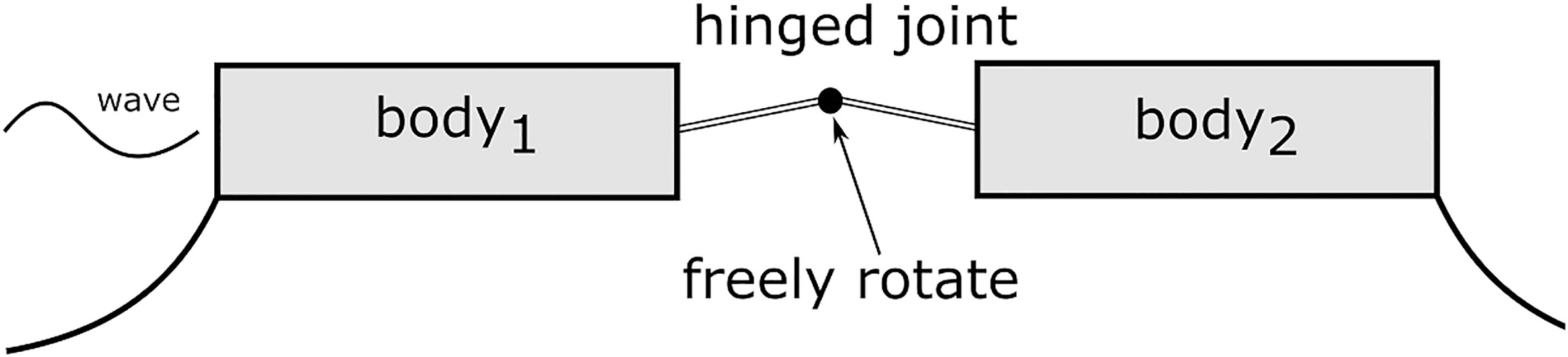
Figure 4 An exemplary multibody platform, connected by a hinged joint.
The floating concept is moored with catenary chains, where mooring lines are attached to the island from several directions. The attached WECs impose a restriction in the sense that mooring legs cannot be connected to these WEC elements. The proposed location of the mooring legs is specified to be located in the outer contour floating modules, as depicted in Figure 3. The fairlead positions of the mooring legs are located at the outer boundaries of each module at keel level. A number of additional modules are connected to either directly or indirectly to the moored modules. Table 4 lists the associated properties of the mooring system.

Table 4 The properties of mooring chains, adopted from van Rossum and Otto (2020).
A key challenge in the multi-use floating island applications is selecting the optimal location. The Mediterranean island configuration is located in the Bay of Montpellier with a mean significant wave height Hs = 1.0 m. The choice of applications for each island was made by a comparison of various scenarios, concerning feasibility, sociologically with emphasis on economical (Ahrouch and Breuls, 2020) The open sea conditions in the Mediterranean are summarized in Table 5.
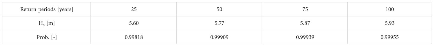
Table 5 Significant wave height in extreme sea states in the Mediterranean, from Hüsken et al. (2019).
To validate the adopted numerical model as well as its numerical setup, calculated hydrodynamic responses are compared to experimental measurements (Thill and Raghu, 2018). The experiments of the standard floating module were performed at model scale with a scaling factor of 70, positioned by four horizontal linear spring-like moorings. For further details, see Jiang et al. (2022a).
Figure 5 plots the computed and measured motion responses of a single floating module in head waves. The module’s motions in surge, heave and pitch over different wave frequencies ω are given, where ζ is the wave amplitude. Symbol denote our results obtained from present weakly nonlinear time-domain simulations; symbol ×, experimental measurements. We see that results obtained from simulations generally agreed well with the results obtained from the experimental measurements at frequencies away from the resonance region. However, at wave frequencies close to the module’s natural frequencies of 0.628 rad/s, our simulations deviate slightly from the experimental measurements. Specifically, the present potential-flow solver underpredicted surge and heave motions, but overpredicted pitch motion.
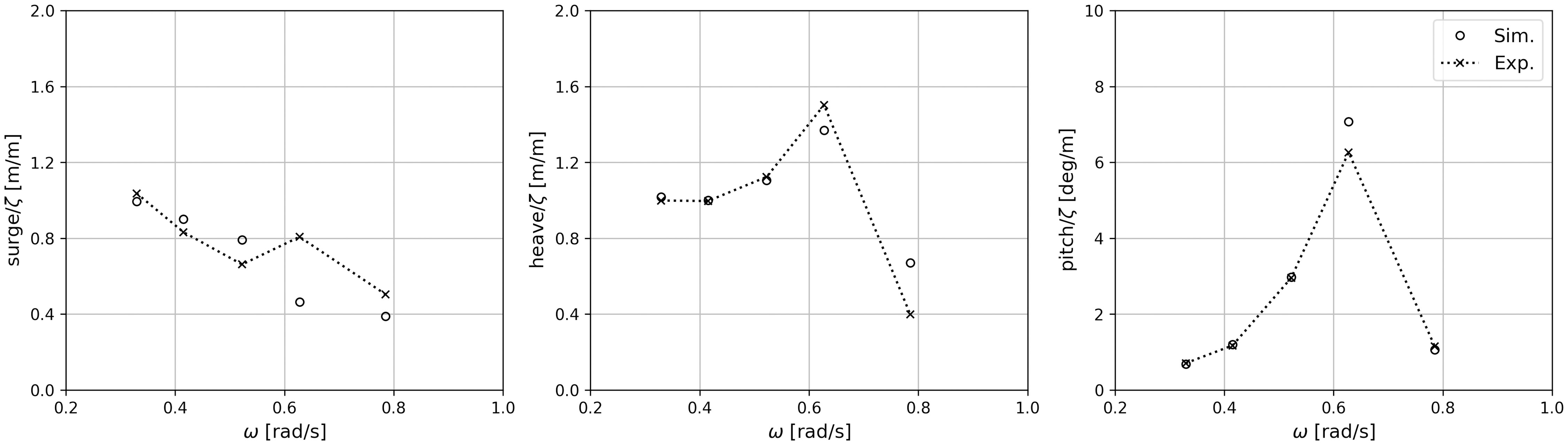
Figure 5 Computed and measured motion responses of a single floating module in head waves.
In terms of a hinged two-body floating system, Figure 6 plots the computed and measured motion responses in head waves. and denote computed motions of bodies 1 and 2, respectively; × and +, measured motions for bodies 1 and 2, respectively. As seen, in waves at frequencies outside the resonance range, simulated results compare reasonable well to experimental measurements. Nevertheless, for waves of frequencies close to the resonance range, our simulations overpredicted the motions of body 1, especially in pitch, but underpredicted the motions of body 2. This may have been due to not implicitly considering viscous effects. Also, our simulations did not account for rotational hinge damping that existed in the experiments. It is worth emphasizing that a relatively inflexible hinge joint was used in the experiment, which was evidenced by the almost identical measurements of bodies 1 and 2. Overall, we may conclude that assessing the response criteria of a multibody floating platform using the adopted numerical model gives conservative results.
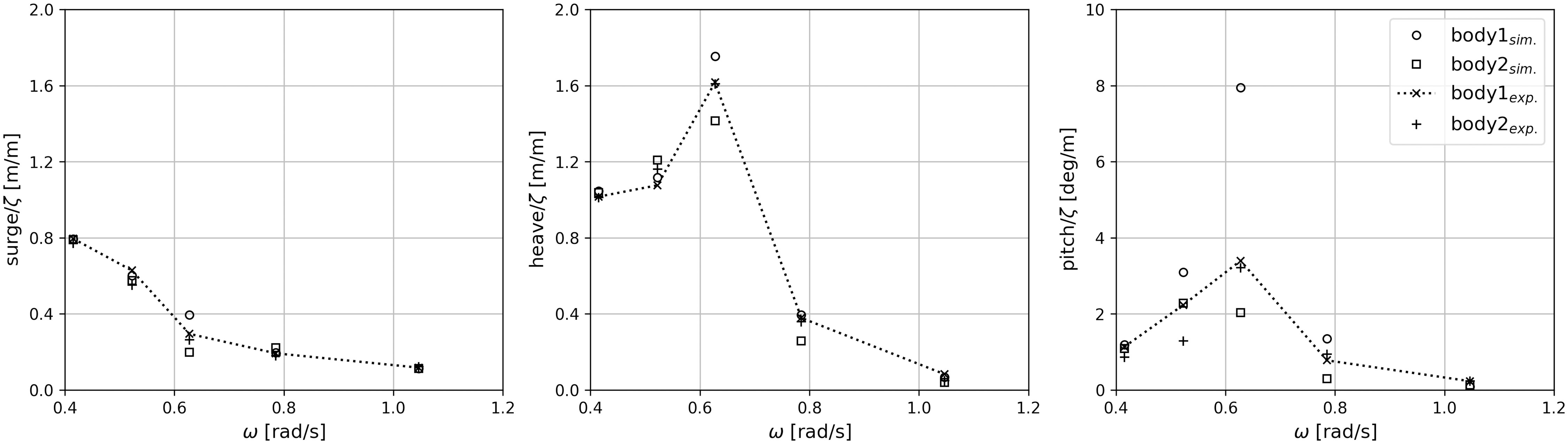
Figure 6 Computed and measured motion responses of a hinged two-module platform in head waves.
In contrast to conventional floating offshore structures, the operability of proposed multibody platform depends not only on the functionality of a standard floating module, but also on its configuration arrangement. To define the corresponding operational conditions, assessments of wave-induced motions and loads which must not exceed a maximum tolerable level are required to be performed. These maximum tolerable levels are defined in terms of motion limiting criteria, such as motion displacements, velocities or accelerations. Together with wave conditions, information on motion limitations is used for platform operability analysis in this section. The analyzed results consist of two groups, including responses in regular waves and short-term responses in irregular waves. This section starts with the estimation of platform’s responses in regular waves. Followed is the combination of these transfer functions with an appropriate wave spectral formulation to derive their response spectrum in irregular seas. Recall that the hinged joints were used in present study, where articulated structures were allowed to rotate around the axis of the hinged joint.
To derive the limiting criteria of proposed floating concept, response amplitude operators (RAOs) in six DoFs of its each floating body are obtained firstly based on time-domain calculations. Again, the weakly nonlinear time-domain approach was preferred in order to take the nonlinear mooring dynamics as well as the kinematic restrictions from hinged joints into account. A floating body can translate along and rotate about three axes, defining a Cartesian coordinate system. The translatory responses in x, y and z directions are, respectively, surge (ξ1), sway (ξ2) and heave (ξ3), while rotational responses about the corresponding axes are roll (ξ4), pitch (ξ5) and yaw (ξ6). For a floating body in a regular wave with frequency of ω and amplitude of ζ, its RAOs are calculated as:
To show the strategy of interpreting simulation results, Figure 7 presents an exemplary time series of surge motion of the floating module at C1R1, where t is time and T is wave period. Herein, symbol B11 identifies the floating body at the intersection of the first column and first row. RAOs are then calculated based on the first-order motion components. Low-frequency motions and mean drifts are crucial for mooring design. Nevertheless, they are excluded from our results and will not be discussed within the present study.
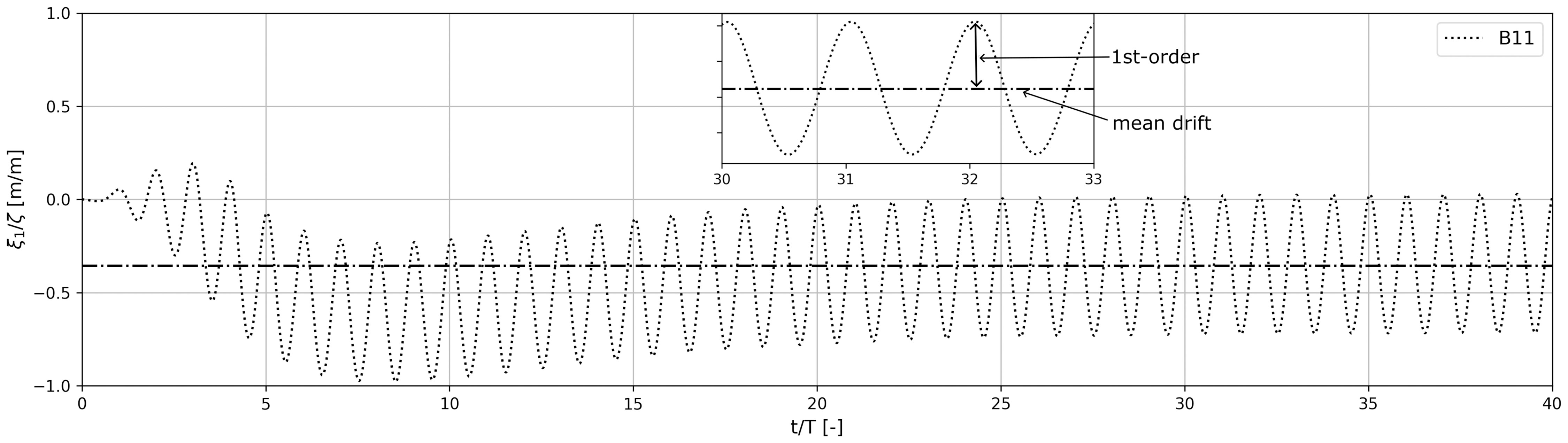
Figure 7 Sample time series of surge motion of the module at R1C1 in a regular wave of ω = 0.33 rad/s.
As shown in Figure 3, the considered floating platform is symmetric about C3. For simplicity, the following demonstrated results of the modules at R1 are limited to C3. Figure 8 shows time series of computed motions of the modules at R1 in a regular wave of ω = 0.33 rad/s. We see that responses of the floating modules at R1 are more or less the same in head waves. Motions in sway and yaw are two orders of magnitude smaller than those in surge and pitch, respectively, which are ignorable. Specifically, we observe that motions in roll deviate from each other, which was dominated by the interactions between these modules as well as the attached WECs.
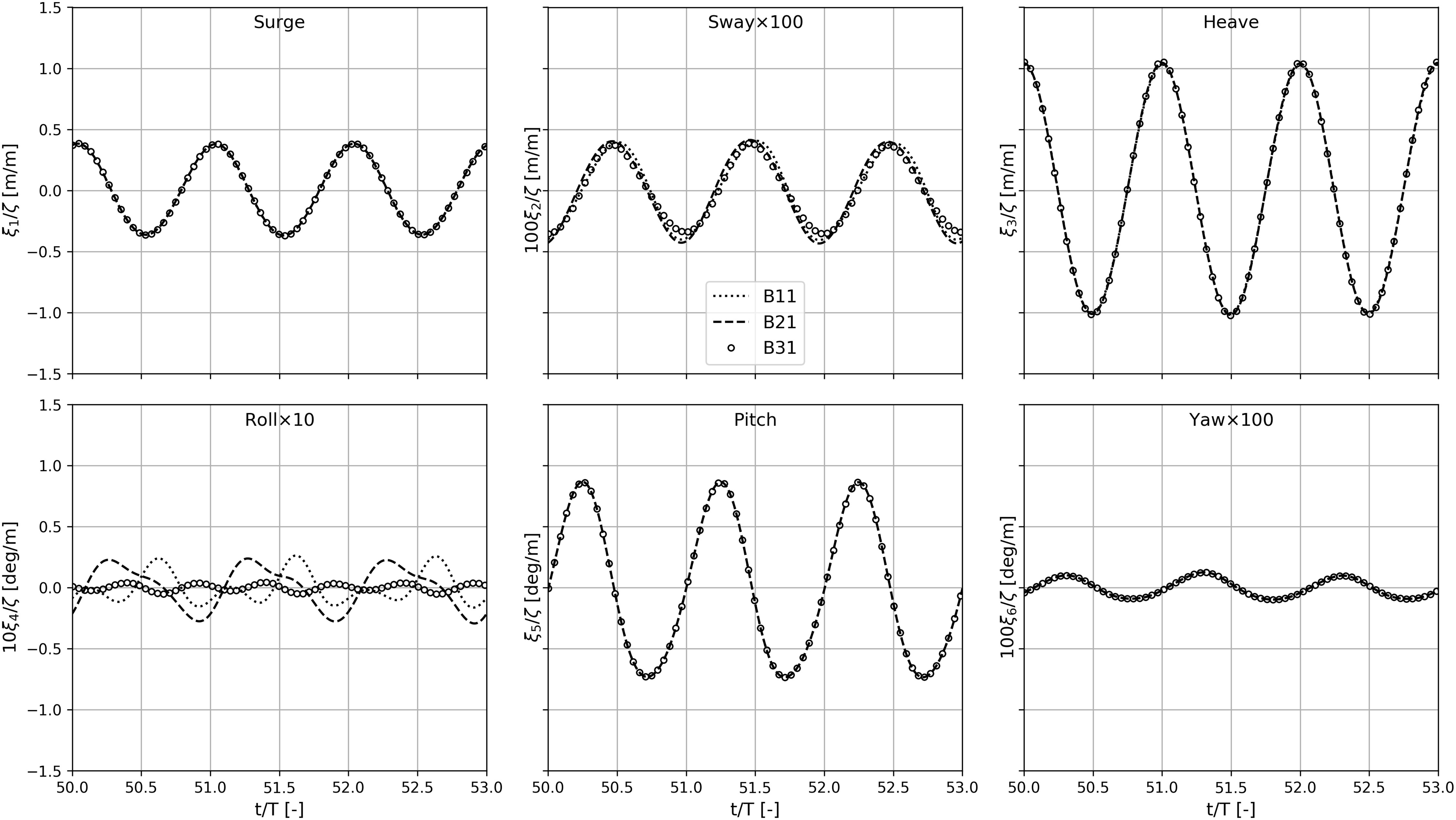
Figure 8 Time series of computed motions of the modules at R1 in a regular wave of ω = 0.33 rad/s.
Figure 9 plots the associated relative motions between the modules at R1 and R2. For example, symbol B31&B32 identifies the relative motions between the floating body at C3R1 and the floating body at C3R2. Comparable motion characteristics with their absolute responses are observed. It is worth noting that relative motions between adjacent modules depend not only on incident wave frequency, but also on the gap width. Accordingly, the time series of computed force acting in the joints connecting the modules at R1 and R2 are plotted in Figure 10. We see that the forces acting in the considered joints have similar magnitudes. Their values are dominated by the force components in surge direction. Weak nonlinearities are observed for the force components in surge direction, as the shape of the force cycles are asymmetric about a vertical nor a horizontal axis. Strong nonlinearities are observed in the force components in sway and heave directions. Nevertheless, they are one order magnitude smaller than those in surge direction.
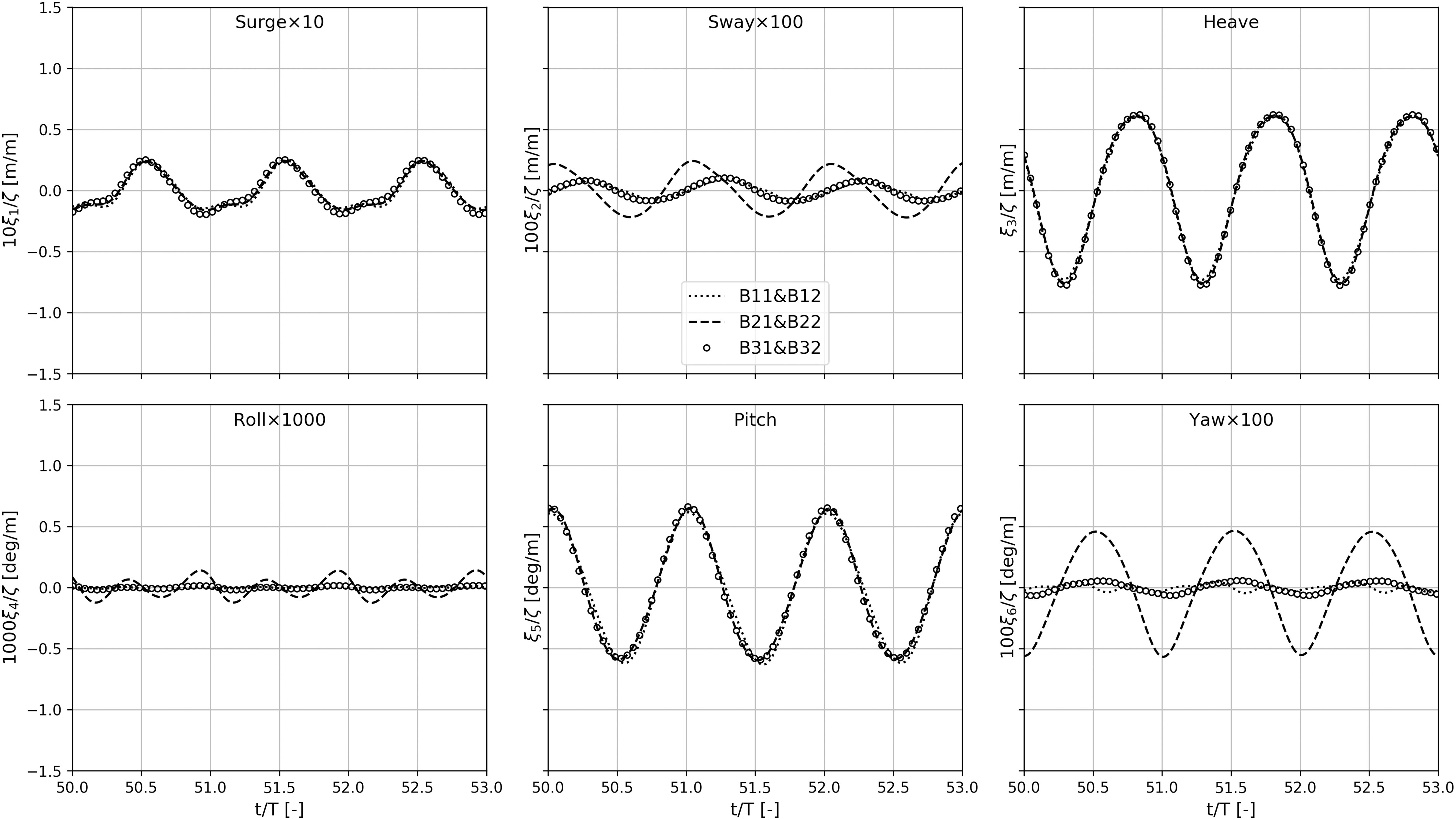
Figure 9 Time series of computed relative motions between the modules at R1 and R2 in a regular wave of ω = 0.33 rad/s.
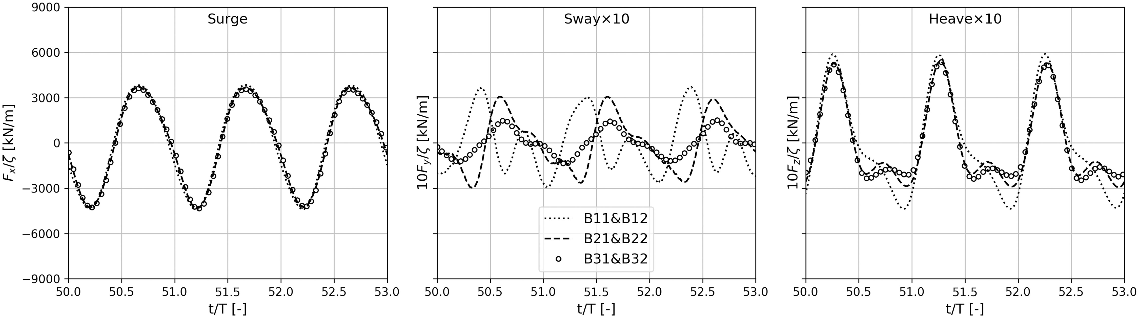
Figure 10 Time series of computed force acting in the joints connecting the modules at R1 and R2 in aregular wave of ω = 0.33 rad/s.
Figure 11 shows the time series of computed tension acting in the mooring lines at fore, port and aft of the platform. As seen, the tension amplitudes are more or less the same for mooring lines at fore, port and aft of the platform. Explicitly, weak nonlinearities are existing for the tensions of port mooring lines. Nonlinearities in the tensions of aft mooring lines are moderate.
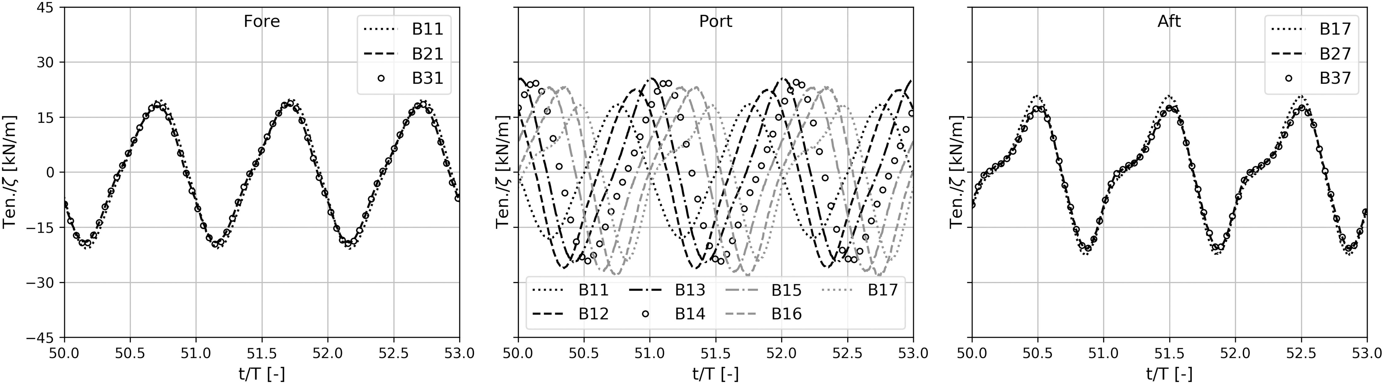
Figure 11 Time series of computed tension acting in the moorings at fore, port and aft in a regular wave of ω = 0.33 rad/s.
The modularity was one of the key elements of the MFS, intended to provide the desired flexibility of additional deck space at sea. Therefore, the limiting criterion may change, depending on the concept and the functionality of the floating platforms. Taking the floating concept in Figure 3 under head seas as an example, a general procedure of defining the limiting criteria is demonstrated. Comparing the provided limiting criteria of Energy and Living in Table 1, one can see that the Energy module is allowed to tolerate larger hydrodynamic responses than the Living modules. Figure 12 gives the RAOs of the interested floating modules in head waves, where only responses in surge, heave and pitch are presented. We see that, for the Energy module (B26) and Living module (B16), which are located in the same row of the floating concept, their hydrodynamic responses are almost identical to each other in head seas. It can be concluded that the limiting criterion of the entire floating concept is determined by the limiting criterion of the Living modules (i.e., B16 and B17). Furthermore, one can see that module B16 has larger hydrodynamic responses than module B17, indicating that the limiting criterion of module B16 is largely responsible for the limiting criterion of the entire floating concept. Therefore, the limiting criteria of pitch motions as well as horizontal and vertical accelerations for module B16 are derived in the following. It must be noted that provided that the associated operability boundaries of other responses, such as, relative motions, velocities, relative velocities, relative accelerations, hinge forces, and mooring tensions are delivered, their limiting criteria maybe obtained accordingly as well.
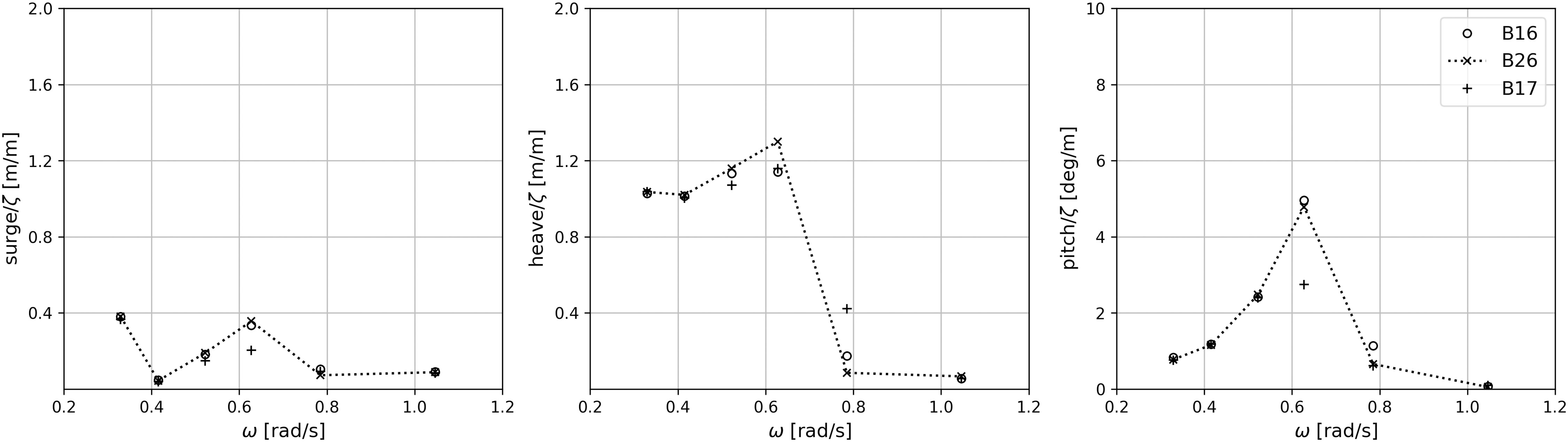
Figure 12 RAOs in surge, heave and pitch of the interested floating modules in head seas.
Responses of the considered floating platform in a specific sea state can be estimated using a short-term spectral analysis, in which transfer functions (i.e., RAOs estimated in Sec. 5.1) are integrated with the selected wave spectrum. In the present study, a JONSWAP spectrum is used to represent a real sea condition:
where is normalization factor, ωp is peak wave frequency, ω is incident wave frequency, σ = 0 07 is spectrum width parameter for ω< ωp and σ = 0.09 for ω > ωp. γ is peak enhancement factor. For a motion response of ξ, its motion spectrum can be derived from the encounter frequency wave spectrum:
The corresponding moments of response ξ are given by:
where i = 0 provides the area; i = 1, the first moment; and i = 2, the moment of inertia of the spectral curve. The significant amplitude of response ξ, defined as the mean value of the highest one-third part of the amplitudes, can be calculated from its spectral density function:
in which RMS is the root mean square value. Wave crest heights in steep waves are higher than those predicted by Gaussian theory because the waves are nonlinear. To account for the most important nonlinearity, the distribution produced from the second-order waves (Forristall, 2000) is adopted to estimate the probability of pitch motions exceeds the limiting value of ξc5 in the present study:
It is a Weibull distribution with
and the mean steepness and Ursell number are given by:
where T1 = Mξ,0/Mξ,1 is the mean response period calculated from the ratio of the first two moments of the response spectrum, K1 is the wavenumber for a frequency of 1/T1, and d is the water depth. Note that the crest height distribution in Eq. 36 does not take into account for higher-order nonlinearities that may lead to rogue waves (Forristall and Cooper, 2016). Nevertheless, measured forces and the survival of structures in severe storms indicate that neglecting deep water breaking waves does not change wave forces significantly (Van de Graaf et al., 1994).
In the present study, short-term statistics are performed for various significant wave heights Hs with different peak period Tp. Hs between 1.0 m and 6.0 m with a resolution of 1.0 m have been calculated, and the estimated Tp varies from 8.0 s to 13.0 s with a resolution of 1.0 s. Figure 13 shows examples of calculated response spectrum of pitch (ξ5), and the horizontal (ξ1) and vertical (ξ3) accelerations of B16 in the sea states with varied Hs but a constant Tp = 9.0 s. We see that compared to the horizontal accelerations, the floating module is dominated by its vertical accelerations. It must be noted that the module response varies greatly based on what frequencies it is encountering in the seas.
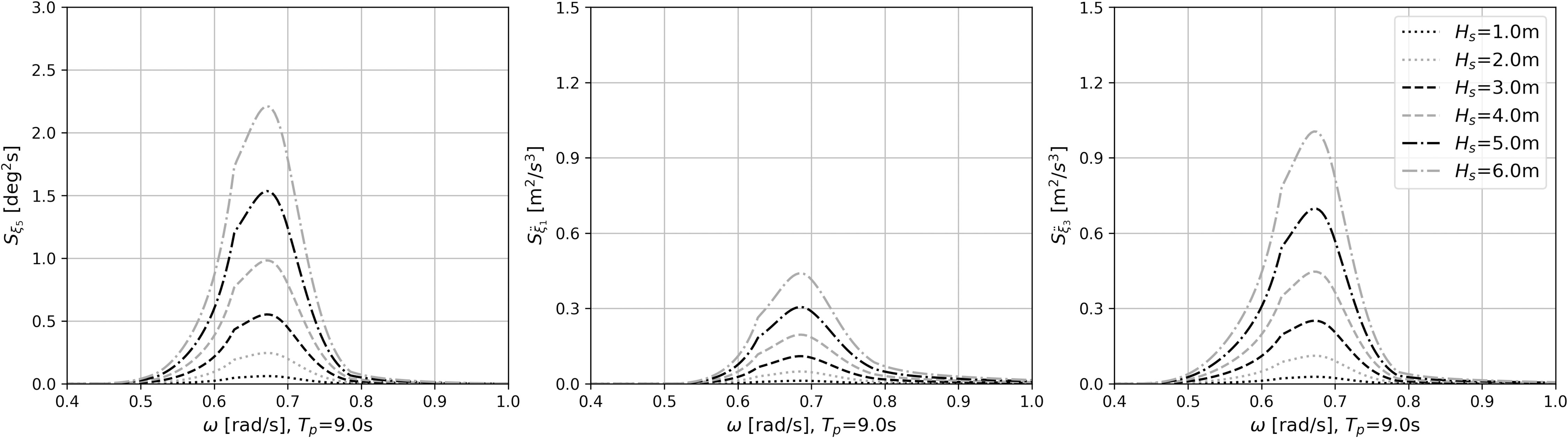
Figure 13 Sample response spectrum of pitch (ξ5), and the horizontal (¨ξ1) and vertical (¨ξ3) accelerations of B16 for varied Hs with a constant Tp=9.0 s.
As listed in Table 1, the limiting criteria of floating modules functioning as energy and living were provided. Each criterion has a different operational limit, designating that each criterion has a maximum Hs as a limitation for the floater to operate for a certain Tp. Nevertheless, all criteria must be fulfilled to set the limits of the floater’s operation. Taking the limiting operational criterion of pitch for B16 as an example, Figure 14 plots the statistics analysis in terms of significant pitch (ξ5(1/3)) and RMS pitch (ξ5(RMS)) of Body16, together with its probability of maximum pitch motions exceeding 5deg for various Hs with different Tp. In the left graph, the significant pitch amplitude for different Tp are plotted against varied Hs. The medium graph shows the associated RMS values of pitch, where RMS of 2deg is taken as the limiting value and the tolerated operational conditions are highlighted in light gray. The associated results of probability of exceeding the maximum pitch amplitude of ξc = 5 deg are given in the right graph of Figure 14. These results could assist a designer or onboard working staff by providing the corresponding tolerated operational conditions. For instance, according to Table 1 the maximum RMS value of rotational motions for the Living modules is 2deg. Provided that the significant wave height Hs = 4.0 m and peak period of Tp = 8.0 s are known from marine weather broadcasts, the corresponding significant and RMS values of pitch can be obtained from the left and medium graphs of Figure 14. One knows that its significant pitch amplitude is 3.5deg under such a sea state, and the corresponding RMS value is 1.7deg, which does not exceed its limiting criterion value of 2deg. Furthermore, based on the right graph of Figure 14, one finds that the probability of pitch motions exceeding 5deg is less than 0.1%, barely occurring.
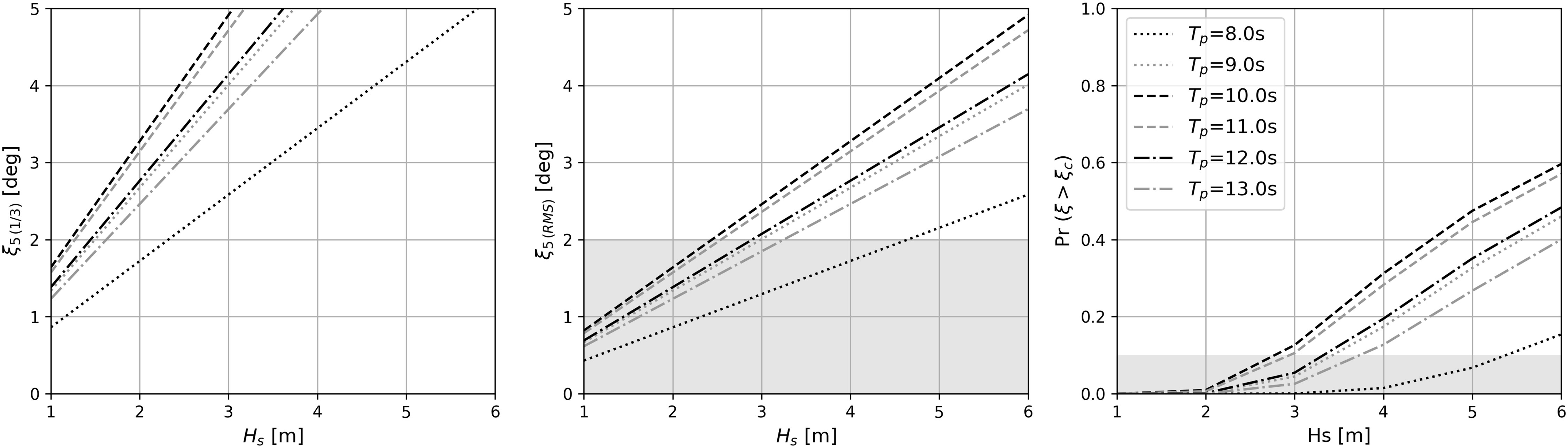
Figure 14 Statistics analysis in terms of significant (ξ5 (1/3)) and RMS pitch (ξ5 (RMS) of Body16, together with its probability of pitch motions exceeding 5deg for various Hs with different Tp.
Apart from the limiting criterion of rotational motions, its vertical and horizontal accelerations also have to be considered for the living modules. As listed in Table 1, the maximum RMS value of horizontal acceleration is 0.3m/s2 for untrained passengers and 0.7m/s2 for experienced workers, respectively. Following the same procedure, their statistics analysis are carried out as well. Their overall results, together with pitch motions are summarized in the operational charts of significant wave height versus peak period, as shown in Figure 15. The light gray region identifies the seaways that the floating modules are subject to normal operating conditions. Comparing the operational sea conditions of vertical acceleration to those of horizontal acceleration and pitch motions, one concludes that the RMS values of vertical acceleration dominate the comfort of persons onboard and, indeed, the final limiting criteria of the entire floating concept.
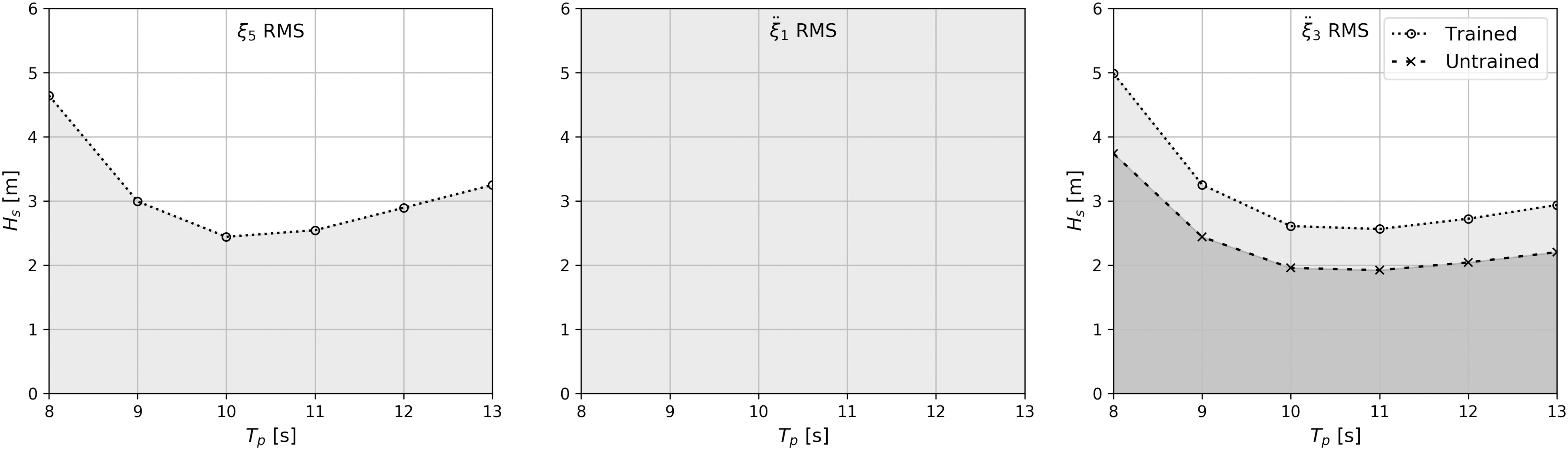
Figure 15 Sea conditions under normal operation for the limiting pitch (ξ3 (RMS)) of 2deg, as well as the corresponding horizontal (¨ξ1) and vertical (¨ξ3) accelerations of B16 for various Hs with different Tp. Here the light gray region identifies the operational seaways for experienced workers; gray region, untrained passengers.
An operability analysis was performed to identify the seakeeping criteria of a moored and articulated multibody floating platform and how the criteria limit its functionality. A two-step strategy was proposed to estimate the wave-induced motions and loads on the target floating concept, including the translational and rotational motions, velocities and accelerations as well as relative motions, velocities and accelerations between adjacent modules. Special cares were given to consider the nonlinear connection and mooring systems. Taking the living module as an example, assessments were carried out for various sea conditions against the prescribed values, for the chosen criteria, to address safety issues due to sever platform responses. Our results show that rotational motions have a significant influence on the platform’s seakeeping performance. Nevertheless, the RMS value of vertical acceleration dominates the comfort of persons onboard, defining the final limiting criterion of the entire platform.
As discussed, the first outcome of this work is to consider the criteria against which the performance of the platforms will be assessed. The second outcome of the present study is giving a general procedure for determining an overview of sea states and corresponding values for the limiting criteria. Again, the modularity was one of the key elements, intended to provide the desired flexibility of additional deck space at sea. Therefore, depending on the concept and the functionality of the floating platforms, their limiting criteria may have to be adjusted according to operations and maintenance. This is because the properties of the floating module, as well as its superstructures may be different from one to another. Combining our previous studies (Jiang, 2021; Jiang et al., 2021; Jiang et al., 2022a; Jiang et al., 2022b; Jiang and el Moctar, 2023), the procedure of defining the limiting criteria of a module floating concept may be summarized as follows:
I. Prepare the geometry and the structural properties of the design module, including mass, center of gravity, moments of inertia, connectors, mooring system, etc.
II. Determine the optimal number of modules and configurations. One can reference to Jiang et al. (2021), which studies the hydrodynamic sensitivity of multi-module structures.
III. Identify the worst case scenarios in terms of environmental conditions by performing computations using linear hydrodynamic methods, linear statistical methods and the scatter table of the sea area.
a. Calculate the response amplitude operators (RAOs) of each module. A 3D time domain (weakly nonlinear) potential flow solver is recommended because restrictions from mechanical joints and mooring systems do need to be taken into account (Jiang et al., 2022a).
b. Compute short-term and/or long-term statistical responses of platform.
IV. Perform computations of platform responses using linear (which is conservative) or nonlinear methods (Jiang and el Moctar, 2023), considering hydroelastic effects for the identified worst case scenarios (see III). One-way coupling of fluid-structure interactions may be considered as accurate enough (Jiang et al., 2022b).
V. Compare results of IV with regard to the providing limiting criteria.
VI. If the limiting criteria are not fulfilled, improve the concept by optimizing its number of modules, arrangement configuration, etc. (see II) or/and limiting the operational sea conditions (e.g., maximum significant wave height, wind speed, etc.) that have to be monitored. If the operational sea conditions lead to responses exceeding the limiting criteria the platform has to be evacuated. A warning system needs to be used.
The original contributions presented in the study are included in the article/supplementary material. Further inquiries can be directed to the corresponding author.
CJ: Conceptualization, Method, Calculations, Analysis, Investigation, Writing – original draft, review and editing. OM: Conceptualization, Method, Resources, Writing – review and editing, Supervision, Project administration, Funding acquisition. GZ: Conceptualization, Method, Resources, Writing – review and editing, Supervision, Project administration, Funding acquisition. All authors contributed to the article and approved the submitted version.
European Union’s Horizon 2020 Research and Innovation Program under grant agreement No. 774253. The German Research Foundation (DFG:448471847) and the National Natural Science Foundation of China (NSFC: 52061135107).
This study is part of the Space@Sea project, funded by European Union’s Horizon 2020 Research and Innovation Program under grant agreement No. 691 774253. We thank all partners of this project. This work partially also contains the outcome of project “Numerical and experimental investigations of hydroelastic effects of very large moored and mechanically coupled multibody offshore floating structures”, jointly funded by the German Research Foundation (DFG: 448471847) and the National Natural Science Foundation of China (NSFC: 52061135107).
The authors declare that the research was conducted in the absence of any commercial or financial relationships that could be construed as a potential conflict of interest.
All claims expressed in this article are solely those of the authors and do not necessarily represent those of their affiliated organizations, or those of the publisher, the editors and the reviewers. Any product that may be evaluated in this article, or claim that may be made by its manufacturer, is not guaranteed or endorsed by the publisher.
Ahrouch G., Breuls M. (2020). Business case Space@Sea D1.1. tech. rep., mocean offshore. Amsterdam: Space@Sea project.
Beck R. (1996). “Nonlinear ship motion computations using the desingularized method,” in Proceedings of the 20th Symposium on Naval Hydrodynamics. (Santa Barbara, CA: National Academy Press), 227–246.
Beukelman W., Huijser A. (1977). Variation of parameters determining seakeeping. Int. Shipbuilding Prog. 24, 171–186. doi: 10.3233/ISP-1977-2427501
Brans S., Rinne A., Kana A. (2021). “Applying a needs analysis to promote daughter craft for year-round access to far-offshore wind turbines,” in Proceedings of the 13th Symposium on High-Performance Marine Vehicles, HIPER '21. (Hamburg, DE: Technische Universität Hamburg-Harburg), 71–87.
Buchner B., De Boer G., De Wilde J. (2004). “The interaction effects of mooring in close proximity of other structures,” in The Fourteenth International Offshore and Polar Engineering Conference. (Toulon, France: International Society of Offshore and Polar Engineers).
Cummins W. (1962). The impulse response function and ship motions. tech. rep (Washington DC: David Taylor Model Basin).
Diamantoulaki I., Angelides D. C. (2010). Analysis of performance of hinged floating breakwaters. Eng. Structures 32, 2407–2423. doi: 10.1016/j.engstruct.2010.04.015
Drummen I., Olbert G. (2021). Conceptual design of a modular floating multi-purpose island. Front. Mar. Sci. 8, 86. doi: 10.3389/fmars.2021.615222
Faltinsen O. (1993). Sea Loads on ships and offshore structures Vol. 1 (Cambridge, England: Cambridge university press).
Feng X., Bai W. (2017). Hydrodynamic analysis of marine multibody systems by a nonlinear coupled model. J. Fluids Structures 70, 72–101. doi: 10.1016/j.jfluidstructs.2017.01.016
Flikkema M., Breuls M., Jak R., de Ruijter R., Drummen I., Jordaens A., et al. (2021a). Floating island development and deployment roadmap. tech. rep., space @ Sea. Wageningen, Space@Sea project.
Flikkema M. M., Lin F.-Y., van der Plank P. P., Koning J., Waals O. (2021b). Legal issues for artificial floating islands. Front. Mar. Sci. 8, 619462. doi: 10.3389/fmars.2021.619462
Flikkema M., Waals O. (2019). Space @ Sea the floating solution. Front. Mar. Sci. 6, 553. doi: 10.3389/fmars.2019.00553
Fonseca N., Guedes Soares C. (2002). Comparison of numerical and experimental results of nonlinear wave-induced vertical ship motions and loads. J. Mar. Sci. Technol. 6, 193–204. doi: 10.1007/s007730200007
Forristall G. Z. (2000). Wave crest distributions: Observations and second-order theory. J. Phys. oceanogr. 30, 1931–1943. doi: 10.1175/1520-0485(2000)030<1931:WCDOAS>2.0.CO;2
Forristall G. Z., Cooper C. K. (2016). “Metocean extreme and operating conditions,” in Springer handbook of ocean engineering. New York City: Springer, Cham, 47–76.
Fournier J., Naciri M., Chen X. (2006). “Hydrodynamics of two side-by-side vessels, experiments and numerical simulations,” in The Sixteenth International Offshore and Polar Engineering Conference. (OnePetro), ISOPE–I–06–349. California, USA: International Society of Offshore and Polar Engineers.
Freeman E. L., Cox R. J., Splinter K. D.. (2017). “Suitable criteria for safe motion limits of a floating pontoon relative to the postural stability of a stationary standing person,” in Australasian Coasts & ports 2017: Working with nature. Barton, ACT: Engineers Australia, PIANC Australia and Institute of Professional Engineers New Zealand, 476.
Fu S., Moan T., Chen X., Cui W. (2007). Hydroelastic analysis of flexible floating interconnected structures. Ocean Eng. 34, 1516–1531. doi: 10.1016/j.oceaneng.2007.01.003
Gao R., Tay Z., Wang C., Koh C. (2011). Hydroelastic response of very large floating structure with a flexible line connection. Ocean Eng. 38, 1957–1966. doi: 10.1016/j.oceaneng.2011.09.021
Ghesmi M., von Graefe A., Shigunov V., Friedhoff B., el Moctar O. (2019). Comparison and validation of numerical methods to assess hydrodynamic loads on mechanical coupling of multiple bodies. Ship Technol. Res. 66, 9–21. doi: 10.1080/09377255.2018.1482100
Gutsch M., Steen S., Sprenger F. (2020). Operability robustness index as seakeeping performance criterion for offshore vessels. Ocean Eng. 217, 107931. doi: 10.1016/j.oceaneng.2020.107931
Huang W., Li B., Chen X., Araujo R. (2018). Numerical and experimental studies on dynamic gangway response between monohull flotel and fpso in non-parallel side-by-side configuration. Ocean Eng. 149, 341–357. doi: 10.1016/j.oceaneng.2017.12.027
Huijsmans R., Pinkster J., De Wilde J. (2001). “Diffraction and radiation of waves around side-by-side moored vessels,” in The Eleventh International Offshore and Polar Engineering Conference. (OnePetro), ISOPE–I–01–061. Stavanger, Norway: International Society of Offshore and Polar Engineers.
Hüsken C., Lucas J., Peckolt J., Assbrock G., Ley J., Olbert G., et al. (2019). Method to harvest energy from relative motion - deliverable 6.1 Space@Sea. research report, NEMOS GmbH; development centre for ship technology and transport systems (Duisburg, Germany: Technische Universität Hamburg).
Iqbal M., Terziev M., Tezdogan T., Incecik A. (2022). Operability analysis of traditional small fishing boats in indonesia with different loading conditions. Ships Offshore Structures, 1–20. doi: 10.1080/17445302.2022.2107300
ITTC (2008). Final report and recommendation to the 25th ittc. proceedings of the 25th ITTC. the seakeeping committee. Fukuoka, JP: International Towing Tank Conference.
Jiang C. (2021). Mathematical modelling of wave-induced motions and loads on moored offshore structures (Dissertation, Duisburg, Essen, Universität Duisburg-Essen). doi: 10.17185/duepublico/
Jiang C., el Moctar O. (2023). Extension of a coupled mooring–viscous flow solver to account for mooring–joint–multibody interaction in waves. J. Ocean Eng. Mar. Energy 9, 93–111. doi: 10.1007/s40722-022-00252-z
Jiang C., el Moctar O., Paredes G. M., Schellin T. E. (2020). Validation of a dynamic mooring model coupled with a rans solver. Mar. Structures 72, 102783. doi: 10.1016/j.marstruc.2020.102783
Jiang C., el Moctar O., Schellin T. E. (2021). Hydrodynamic sensitivity of moored and articulated multibody offshore structures in waves. J. Mar. Sci. Eng. 9, 1028. doi: 10.3390/jmse9091028
Jiang C., el Moctar O., Schellin T. E. (2022a). Capability of a potential-flow solver to analyze articulated multibody offshore modules. Ocean Eng. 266, 112754. doi: 10.1016/j.oceaneng.2022.112754
Jiang C., el Moctar O., Schellin T. E., Qi Y. (2022b). “Numerical investigation of hydroelastic effects on floating structures,” in WCFS2020 (Springer, Singapore: Springer), 309–330.
Jiang C., el Moctar O., Zhang G., Schellin T. E. (2022c). “Simulation of a moored multibody offshore structure articulated by different joints in waves,” in ASME 2022 41st International Conference on Ocean, Offshore and Arctic Engineering, Vol. 85901. Hamburg, Germany: American Society of Mechanical Engineers.
Jiang C., Xu P., el Moctar O., Zhang G. (2022d). Analysis of a moored and articulated multibody offshore system in steep waves. J. Offshore Mechanics Arctic Eng. 145 (4), 1–22. doi: 10.1115/1.4056522
Kashiwagi M., Endo K., Yamaguchi H. (2005). Wave drift forces and moments on two ships arranged side by side in waves. Ocean Eng. 32, 529–555. doi: 10.1016/j.oceaneng.2004.09.005
Kodan N. (1984). The motions of adjacent floating structures in oblique waves. J. Energy Resour. Technol. 106, 199–205. doi: 10.1115/1.3231038
Kondo T., Vadus J. (1991). “Ocean space utilization: Trends and needs,” in OCEANS 91: Ocean technologies and opportunities in the pacific for the 90’s(Honolulu HI: Institute of Electrical and Electronic Engineers). doi: 10.1109/OCEANS.1991.627999
Koo B., Kim M. (2005). Hydrodynamic interactions and relative motions of two floating platforms with mooring lines in side-by-side offloading operation. Appl. Ocean Res. 27, 292–310. doi: 10.1016/j.apor.2006.02.001
Løken A. (1981). “Hydrodynamic interaction between several floating bodies of arbitray form in waves,” in International Symposium on Hydrodynamics in Ocean Engineering, Vol. 2. Trondheim, Norway: Norwegian Hydrodynamic Laboratories, 745–779.
Lamas-Pardo M., Iglesias G., Carral L. (2015). A review of very large floating structures (vlfs) for coastal and offshore uses. Ocean Eng. 109, 677–690. doi: 10.1016/j.oceaneng.2015.09.012
Lee C.-H., Newman J. (2000). An assessment of hydroelasticity for very large hinged vessels. J. fluids structures 14, 957–970. doi: 10.1006/jfls.2000.0305
Li B. (2020). Multi-body hydrodynamic resonance and shielding effect of vessels parallel and nonparallel side-by-side. Ocean Eng. 218, 108188. doi: 10.1016/j.oceaneng.2020.108188
Moreno E. C., Fourtakas G., Stansby P., Crespo A. (2020). “Response of the multi-float wec m4 in focussed waves using sph,” in Developments in renewable energies offshore (London: CRC Press), 199–205.
Newman J. N. (1994). Wave effects on deformable bodies. Appl. ocean Res. 16, 47–59. doi: 10.1016/0141-1187(94)90013-2
Obeng F., Domeh V., Khan F., Bose N., Sanli E. (2022). Capsizing accident scenario model for small fishing trawler. Saf. Sci. 145, 105500. doi: 10.1016/j.ssci.2021.105500
Pauw W. H., Huijsmans R. H., Voogt A. (2007). “Advances in the hydrodynamics of side-by-side moored vessels,” in ASME 2007 26st International Conference on Ocean, Offshore and Arctic Engineering, Vol. 42703. California, USA: American Society of Mechanical Engineers, 597–603.
Peng H. H., Qiu W., Meng W., Chen M., Lundrigan B., Gardiner T. (2020). Experimental studies and time-domain simulation of a hinged-type wave energy converter in regular waves. Mar. Syst. Ocean Technol. 15, 1–15. doi: 10.1007/s40868-020-00073-5
Rogne Ø.Y. (2014). Numerical and experimental investigation of a hinged 5-body wave energy converter (Norwegian University of Science and Technology: Norges teknisk-naturvitenskapelige universitet, Fakultet for ingeniørvitenskap og teknologi, Institutt for marin teknikk). (Doctoral dissertation, PhD thesis).
Sariöz K., Narli E. (2005). Effect of criteria on seakeeping performance assessment. Ocean Eng. 32, 1161–1173. doi: 10.1016/j.oceaneng.2004.12.006
Schwarzkopf M.-A., Scheu M. N., Altay O., Kollos A. (2018). “Whole body vibration on offshore structures: An evaluation of existing guidelines for assessing low-frequency motions,” in The Eleventh International Offshore and Polar Engineering Conference. (OnePetro), ISOPE–I–18–517. Stavanger, Norway: International Society of Offshore and Polar Engineers.
Scorpio S., Beck R., Korsmeyer F. (1996). “Nonlinear water wave computations using a multipole accelerated, desingularized method,” in Twenty First Symposium on Naval Hydrodynamics. Trondheim, Norway: National Academy Press, 64–74.
Seithe G., el Moctar O. (2019). “Wave-induced motions of moored and coupled multi-body offshore structures,” in 11th international workshop on ship and marine hydrodynamic(Hamburg, Germany: TUHH Universitätsbibliothek), 85–97.
Souravlias D., Dafnomilis I., Ley J., Assbrock G., Duinkerken M. B., Negenborn R. R., et al. (2020). Design framework for a modular floating container terminal. Front. Mar. Sci. 7, 545637. doi: 10.3389/fmars.2020.545637
Subramani A. K. (1998). “Fully nonlinear free-surface computations for arbitrary and complex hull forms,” in roceedings of the 22nd Symposium on Naval Hydrodynamics. Washington DC: National Academy Press, 1–12.
Suzuki H., Bhattacharya B., Fujikubo M., Hudson D., Riggs H., Seto H., et al. (2006). Issc committee vi. 2: Very large floating structures. 16th ISSC 2, 394–442.
Taghipour R., Moan T. (2008). “Efficient frequency-domain analysis of dynamic response for the multi-body wave energy converter in multi-directional wave,” in The Eighteenth International Offshore and Polar Engineering Conference. (OnePetro), ISOPE–I–08–269. Vancouver, Canada: International Society of Offshore and Polar Engineers.
Tamis J. E., Jongbloed R. H., Piet G. J., Jak R. G. (2021). Developing an environmental impact assessment for floating island applications. Front. Mar. Sci. 8, 664055. doi: 10.3389/fmars.2021.664055
Tello M., e Silva S. R., Soares C. G. (2011). Seakeeping performance of fishing vessels in irregular waves. Ocean Eng. 38, 763–773. doi: 10.1016/j.oceaneng.2010.12.020
Thill C., Raghu S. P. (2018). Model tests report D4.3 Space@Sea. tech. rep (Delft, Netherlands: Delft University of Technology).
Van de Graaf J., Tromans P., Efthymiou M. (1994). “The reliability of offshore structures and its dependence on design code and environment,” in Offshore Technology Conference. Houston, Texas: Offshore Technology Conference Printed by Curran Associates, 1931–1943.
van Oortmerssen G. (1979). Hydrodynamic interaction between two structures floating in waves. Proc. BOSS’79, 339–356.
van Rossum T., Otto W. (2020). Mooring system design - deliverable 3.3 Space@Sea. tech. rep., bluewater (Hoofddorp, Netherlands: Maritime Research Institute Netherlands).
Vibration M. (1984). Shock-guidelines for the overall evaluation of vibration in merchant ships Vol. 6954 (Geneva, Switzerland: Draft International Standard).
von Graefe A., Shigunov V., el Moctar O. (2015). Rankine source method for ship–ship interaction problems. J. Offshore Mechanics Arctic Eng. 137, 021601–10. doi: 10.1115/1.4029316
Young I. R., Ribal A. (2019). Multiplatform evaluation of global trends in wind speed and wave height. Science 364, 548–552. doi: 10.1126/science.aav9527
Zhu H., Sueyoshi M., Hu C., Yoshida S. (2017). “Modelling and attitude control of a shrouded floating offshore wind turbine with hinged structure in extreme conditions,” in 2017 IEEE 6th International Conference on Renewable Energy Research and Applications (ICRERA). IEEE: San Diego, CA, USA, 762–767.
Keywords: time-domain, seakeeping, limiting criterion, multibody interaction, mooring dynamics, mechanical joint, multi-use platform
Citation: Jiang C, el Moctar O and Zhang G (2023) Seakeeping criteria of a moored and articulated multibody floating platform in head seas. Front. Mar. Sci. 10:1138235. doi: 10.3389/fmars.2023.1138235
Received: 05 January 2023; Accepted: 01 February 2023;
Published: 23 February 2023.
Edited by:
Wei-Bo Chen, National Science and Technology Center for Disaster Reduction (NCDR), TaiwanReviewed by:
Spyros Hirdaris, Aalto University, FinlandCopyright © 2023 Jiang, el Moctar and Zhang. This is an open-access article distributed under the terms of the Creative Commons Attribution License (CC BY). The use, distribution or reproduction in other forums is permitted, provided the original author(s) and the copyright owner(s) are credited and that the original publication in this journal is cited, in accordance with accepted academic practice. No use, distribution or reproduction is permitted which does not comply with these terms.
*Correspondence: Changqing Jiang, Y2hhbmdxaW5nLmppYW5nQHVuaS1kdWUuZGU=
Disclaimer: All claims expressed in this article are solely those of the authors and do not necessarily represent those of their affiliated organizations, or those of the publisher, the editors and the reviewers. Any product that may be evaluated in this article or claim that may be made by its manufacturer is not guaranteed or endorsed by the publisher.
Research integrity at Frontiers
Learn more about the work of our research integrity team to safeguard the quality of each article we publish.