 Zhiyong Duan
 Yurui Zhang
 Canjun Yang
- State Key Laboratory of Fluid Power and Mechatronic Systems, Zhejiang University, Hangzhou, China
At present, contact watertight connectors are commonly utilized for the connection between underwater electromechanical equipment and the seabed observation network. Such traditional watertight connectors are easy to be irreversibly worn when plugging and unplugging, however, they have complicated sealing structures and limited service life. This paper designs a Non-contact Wet Mateable connector for Optical Communication and Power Transmission (OCPT-NWMC), which is based on technology of Contactless Power Transmission (CLPT) and optical communication. Docking structure of the sockets and plugs are designed, facilitating Remotely Operated Vehicle (ROV) to operate. A prototype of the OCPT-NWMC was established. The experimental results show that the connector designed can achieve 200W power transmission, with a maximum power transmission efficiency of 94%. The communication bandwidth reaches 18MHz. The OCPT-NWMC can assist the rapid and safe deployment and operation of seabed observation network.
1 Introduction
With the rapid development of seabed observation technology, the development of deep sea has been improved (Mikada and Chave, 2004). The seabed observation network system provides a standard power supply and communication interface for seabed observation equipment, making long-term and continuous ocean observation possible (Favali et al., 2011; Best et al., 2014; Lin and Yang, 2020)
The construction of a large-scale seabed observation network is difficult, which is almost impossible to be deployed it in a holistic manner. The underwater wet mateable connector can divide these engineering projects into different functional modules, which are deployed separately. Then Remotely Operated Vehicle (ROV) complete the connection of each module (Kawaguchi et al., 2008; Christ and Wernli, 2014). The operating principle of the commonly used wet mateable connector is isolated from the high-pressure seawater through the sealing rubber (Painter and Flynn, 2006; Rémouit et al., 2018), with complex structure, large plugging force and difficult operation process. The interface may be severely worn, causing a limited number of plugging and unplugging.
Contactless Power transmission (CLPT) can be utilized to replace the traditional contact wet mateable connector (Baer et al., 2009). Electromagnetic induction type CLPT has short transmission distance and high transmission efficiency, which is widely used in underwater electrical equipment, electric vehicles, biomedicine and robotics.
Baer C M et al. (Granger et al., 2013). developed a non-contact wet mateable connector based on CLPT, realizing 10W power transmission by coaxial nested coupling coils and signal rate of 600kbps by bidirectional optical communication. Li et al. proposed the coil turns optimization method and the coil structure design method of the loosely coupled CLPT coils in the marine environment (Li et al., 2017). The transmission of power and signal is jointly realized, with maximum 400W power transmission and 2Mbps data rate through WIFI. However, the communication bandwidth is low and the connector is large. Shi et al. designed a non-insert wet mateable connector based on mathematical modeling and numerical calculation (Shi et al., 2020). 130W power and 73Mbps full-duplex data through wireless router can be transmitted at the same time.
Optical communication has been applied underwater over small distance transmission (Khalighi et al., 2017). According to the electromagnetic wave characteristics, the blue-green light frequency band has an attenuation window in seawater (Li S et al., 2019). Compared with underwater acoustic communication and electromagnetic wave communication, optical communication is small, low in energy consumption and higher in communication rate (Kaushal and Kaddoum, 2016).
Doniec M W et al. developed an underwater point-to-point optical communication equipment and carried pool experiments (Doniec and Rus, 2015). Aqua Optical II is able to achieve a communication speed of 5.1Mbps within 50m (Doniec and Rus, 2010). Xu et al. used OFDM technology and a single LED to achieve underwater 2m transmission, and realized a data rate of 161Mbps (Xu et al., 2016). Chen et al. applied underwater laser communication to the positioning and navigation of underwater autonomous vehicles. The system achieved a data rate of 1 Mbit/s at 4 m (Chen et al., 2022).
Non-contact power transmission and optical communication technologies have been respectively applied in ocean observation projects (Li Y et al., 2019; Lin et al., 2019; Ali et al., 2020). This paper integrates the two technologies to design a non-contact wet mateable connector for optical communication and power transmission. Docking structure of the socket and plug is designed, ensuring high precision of the axial docking and facilitating ROV to operate. The OCPT-NWMC can assist the rapid and safe deployment and operation of seabed observation network.
2 Overall design of OCPT-NWMC
The OCPT-NWMC is mainly composed of input source, the primary side socket and the secondary side plug, watertight connectors. The external interfaces of power and communication are realized through watertight cables and connectors. The schematic diagram of the OCPT-NWMC is shown in Figure 1A. The superior junction box of seabed observation network provides electric power and signals to the connector through the watertight connector. Since the current mainstream of the ocean observation network adopts direct current, the junction box here provides DC voltage. For power transmission, the AC voltage is generated by the inverter circuit. The high-frequency electromagnetic wave is emitted by the primary coils. On the secondary side, coils convert the received electromagnetic wave into AC voltage, which is then rectified and output.
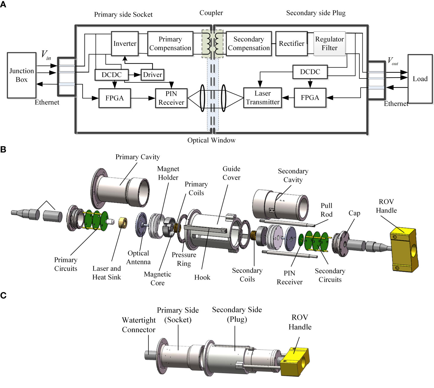
Figure 1 The OCPT-NWMC (A) schematic diagram (B) exploded view (C) assembled diagram of the mechanical structures.
For signal transmission, the laser driving circuit receives the signal, then the laser is driven. The signal is transmitted to seawater channel by the optical antenna of the transmitter. On the secondary side, the signal reaches the optical antenna of the receiver. The PIN tube converts the optical signal into electrical signal. And the signal is conditioned. Finally, the load receives power and signal through the watertight connector.
The exploded view of the mechanical structures of OCPT-NWMC shown in Figure 1B. The docking of the socket and plug is reliably achieved by the hook. The ROV operates the handle so that the locking hook is stuck on the groove of the primary cavity. Under the action of the guide cover and the hook, the two sides are closely connected. The seawater on the end face is squeezed, reducing the loss of optical signal. When separating two sides, the ROV pulls on the handle end. The locking hook is stretched, making the locking invalid. The assembled OCPT-NWMC is shown in Figure 1C.
3 Principles of OCPT-NWMC
3.1 Principle of CLPT system in seawater environment
The mutual inductance model of CLPT system in seawater is shown in Figure 2. Lp, LS are respectively the self-inductances of the primary side and the secondary side. Rp, RS are the respective internal resistances of the coils. The coupling of the two coils is described by mutual inductance M. The coupling coefficient k is used to express the degree of coupling between the two coils.
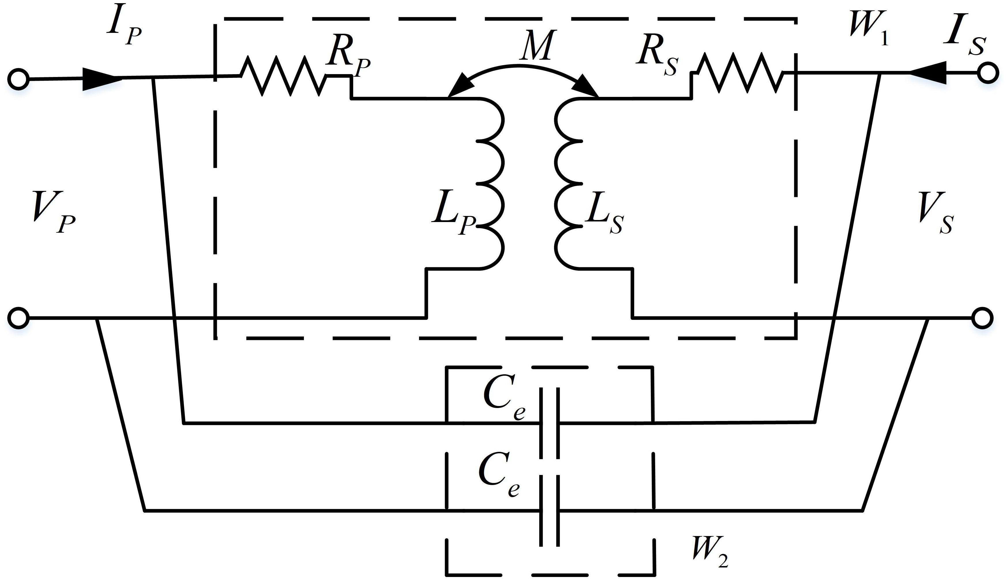
Figure 2 A two-port network model of the equivalent mutual inductance model of CLPT system in seawater.
According to the reflected impedance theory, the impedance reflected from the secondary side to the primary side can be calculated as:
Zr is called the reflection impedance, Rr, Xr are the reflection resistance and reflection reactance, respectively. The power absorbed by the reflection resistance represents the transmission capability of the coupling coil. The reflection reactance of the system generates reactive power, reducing the power factor. For the convenience of analysis, a two-port network model of the equivalent mutual inductance model of CLPT system in seawater is established. Ce is the distributed capacitance of seawater between the loosely coupled coils caused by the high conductivity of seawater. The model is equivalent to the parallel connection of a mutual inductance model network in the air and a distributed capacitance network.
The transmission equation of the two-port network is defined as:
Where T is the transmission matrix, which is converted to total admittance matrix:
In the formula (4), T is the transmission matrix. ZP and ZS respectively represent open-circuit impedances on two sides, i.e. ZP = jωLP + RP, ZS = jωLS + RS. And κ = ωCe|Z1|, where |Z1| = (jωLP + RP)(jωLS + RS) − (jωM)2.
The transmission equation of the equivalent mutual inductance model of CLPT system in seawater is:
If the load is RL, then the output voltage is, then the output voltage is:
The input impedance of the network for seawater is:
The distributed capacitance Ce of the coil for length l, coil diameter d, inner radius r can be estimated
Where ε is the dielectric constant of seawater.
The input impedance of the network for air is
The equivalent mutual inductance model in seawater and in air are compared. The frequency characteristics of the impedance mode and impedance angle are shown in Figure 3.
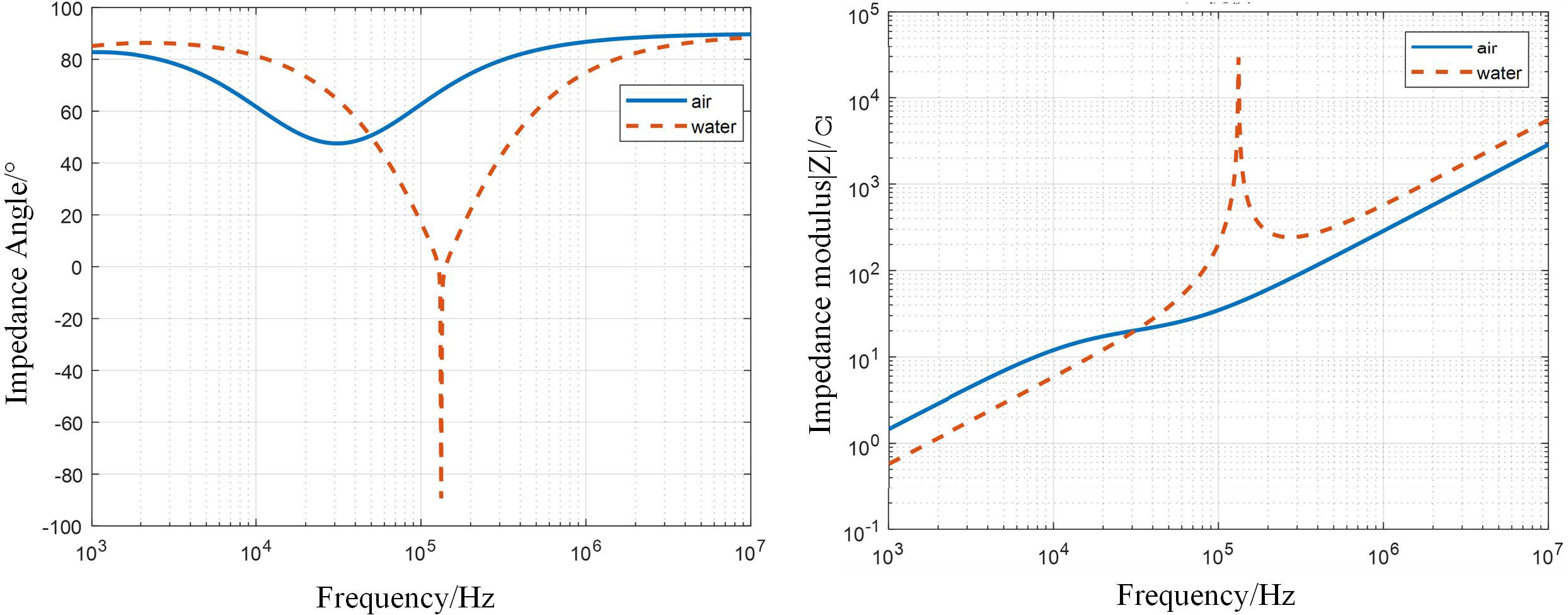
Figure 3 Frequency characteristics of the mutual inductance model in seawater and air.
It is shown that, under low operating frequency of the system, the system is hardly affected due to the large distributed capacitance and reactance of seawater. As the operating frequency of the system increases, the distributed capacitance and the inductance of the coils form an LC resonant circuit, causing a peak of the impedance mode of the system. The frequency of the CLPT system studied in this paper is between 10kHz and 100kHz, which belongs to the low frequency band. Therefore, the mutual inductance model can be simplified to the situation in the air, reducing the complexity of system design.
3.2 Modulation algorithm for underwater optical communication
In the actual system, optical communication is limited by power and bandwidth, so the modulation technology needs to consider power consumption, bandwidth and difficulty of implementation. On-Off Keying (OOK) modulation is used in this paper (Gayathri et al., 2015; Wang et al., 2016). In the OOK modulation system, the baseband rectangular pulse of digital “0” or “1” is used to control a continuous carrier. The carrier is output intermittently. The presence or absence of carrier output corresponds to sending 1 or 0. The OOK signal can be considered as a unipolar rectangular pulse sequence multiplied by the carrier:
Where g(t) is a rectangular pulse with a duration of Tb ak represents the 01 sequence. ωc is the carrier frequency, and θc is the initial phase of the carrier.
Since the spectrum of the rectangular pulse sequence of the baseband signal is infinitely wide, the pulse signal will expand in time, causing intersymbol interference and increasing the bit error rate at the receiving end. In order to use the channel effectively, it is necessary to compress the spectral bandwidth to improve the frequency band utilization. The most widely used filter that satisfies the Nyquist first criterion is the raised cosine roll-off filter, which is a finite impulse response (FIR) filter. The transfer function of FIR is:
Where α (0≤α≤1) is the roll-off factor of shaping filter. The value of α determines the bandwidth of the system. In order to improve the frequency band utilization, the value of α should be as small as possible. However, when α gets smaller, synchronizing the bits at the receiving end becomes more difficult, and the system bit error rate becomes larger. To reduce the sampling pulse error, it is usually chosen as α ≥ 0.2.
Set the baseband signal rate Rb = 1Mbps, the carrier frequency fc = 50MHz, the sampling frequency fs = 8Rb, the shaping filter coefficients fs = 8Rb, and shaping filter factor α = 0.35. The spectrum of the OOK signal is shown in Figure 4.
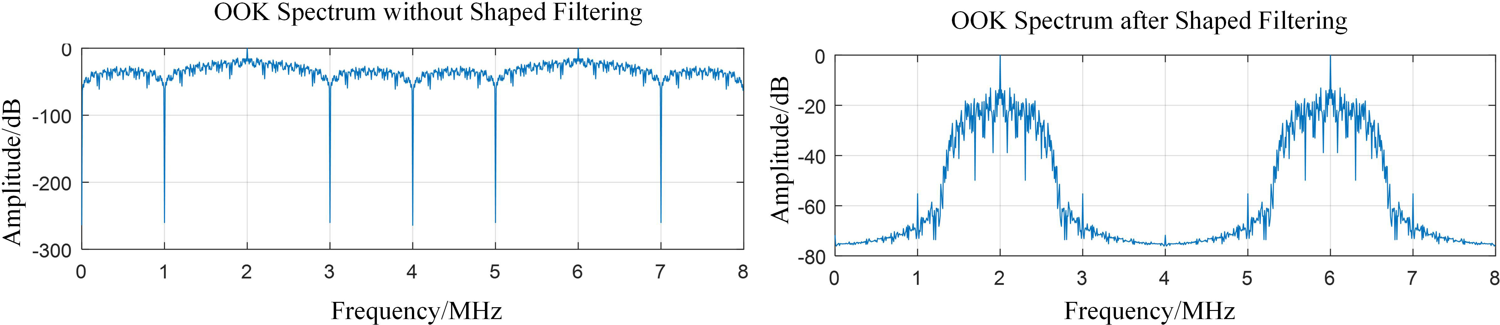
Figure 4 OOK signal spectrum in MATLAB.
It is shown that the frequency components of the OOK signal spectrum after the shaping filter other than the main lobe have been filtered out. Since the signal generated by MATLAB is a real signal, the signal spectrum is symmetrical about half of the sampling frequency (4MHz). According to the sampling theory, the sampled carrier frequency is fas = kfs ± fc, where k is an integer. When k = 7, the sampled carrier frequency component is moved to 6MHz. It can be seen that after the shaping filter, the energy of the signal is more concentrated, making the decision more conducive.
OOK signal demodulation adopts non-coherent demodulation. It mainly uses envelope detection. The signal is first full-wave rectified then low-pass filtered. Sampling judgment is performed at the position where the eye diagram opens the most, to restore the original signal. The method is simple to implement, since the synchronous carrier does not need to extract.
4 System design of OCPT-NWMC
4.1 Structure of loosely coupled coils
The core of the design of CLPT system is the loosely coupled coils, which directly determines the output power and affects the transmission efficiency of the system. In this paper, the requirement of the axial positioning accuracy of the connector is low, and relative rotation of both sides is allowed. For small radial dimensions and high coupling coefficient, the coaxial and parallel coil structure is selected. GU-type magnetic core made of ferrite material is utilized. The magnetic core covers almost all the coils, making the magnetic leakage small. The coil structure and magnetic field simulation are shown in. The coil and the magnetic core are exposed to seawater. High-frequency electromagnetic waves induce eddy currents in the seawater, resulting in a large power loss. As shown in Figure 5, the magnetic core window is potted with epoxy resin to prevent the infiltration of seawater.
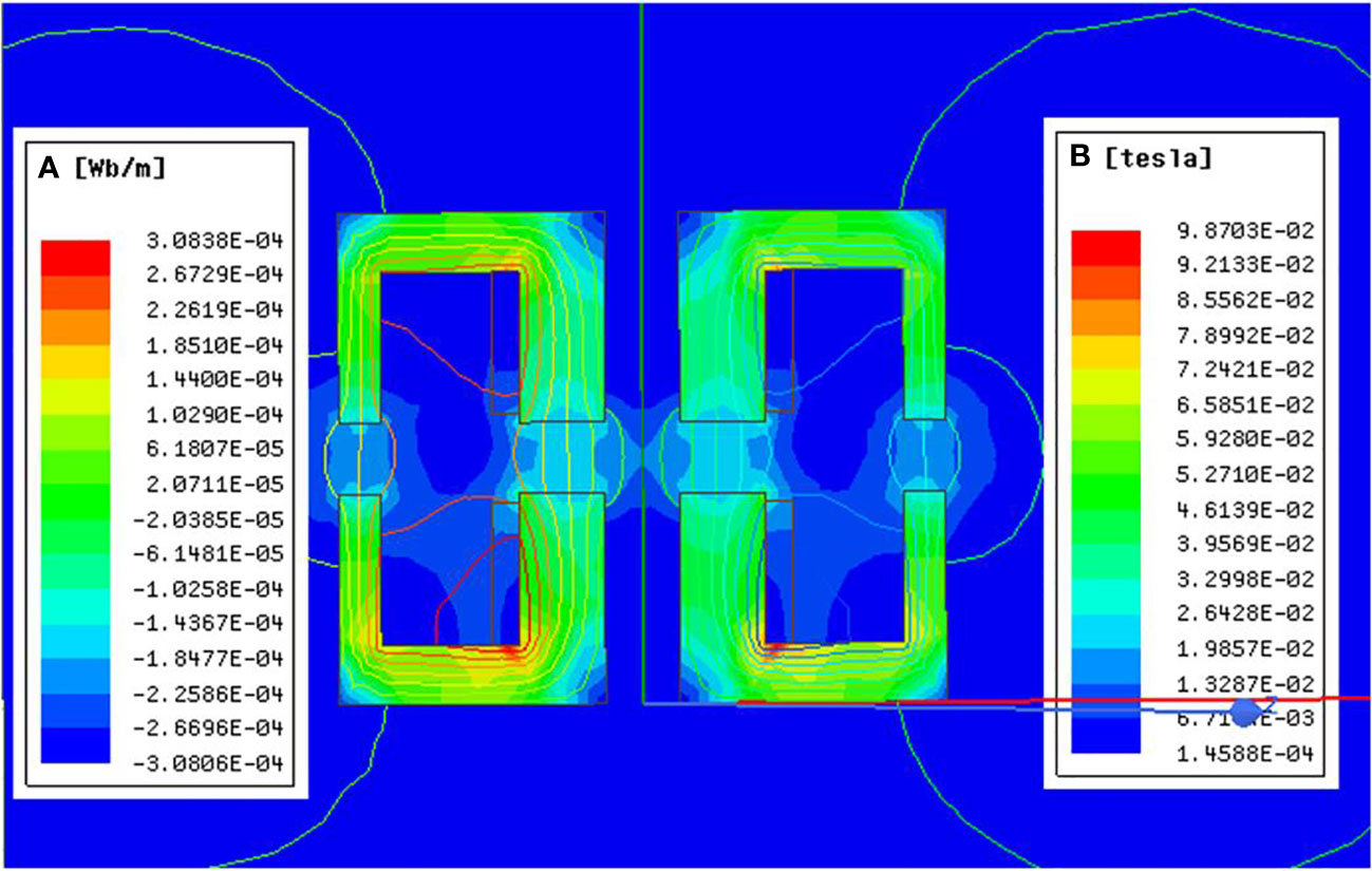
Figure 5 The magnetic field simulation of the coil.
4.2 Circuit design
The schematic diagram of the OPCT-NWMC circuit is shown in Figure 6. To improve the CLPT transmission performance, a compensation circuit is employed to eliminate reflected reactance (Gati et al., 2017). Compared to the four basic compensation methods, dual-LCC topology has better frequency characteristics and greater transmission power(Siqi Li et al., 2015). The dual-LCC topology compensation circuit adds additional compensation inductance, and additional compensation capacitance, to form a high-order resonant network. It has a higher power factor, less voltage and current stress on the switching device, and is easy to achieve soft switching.
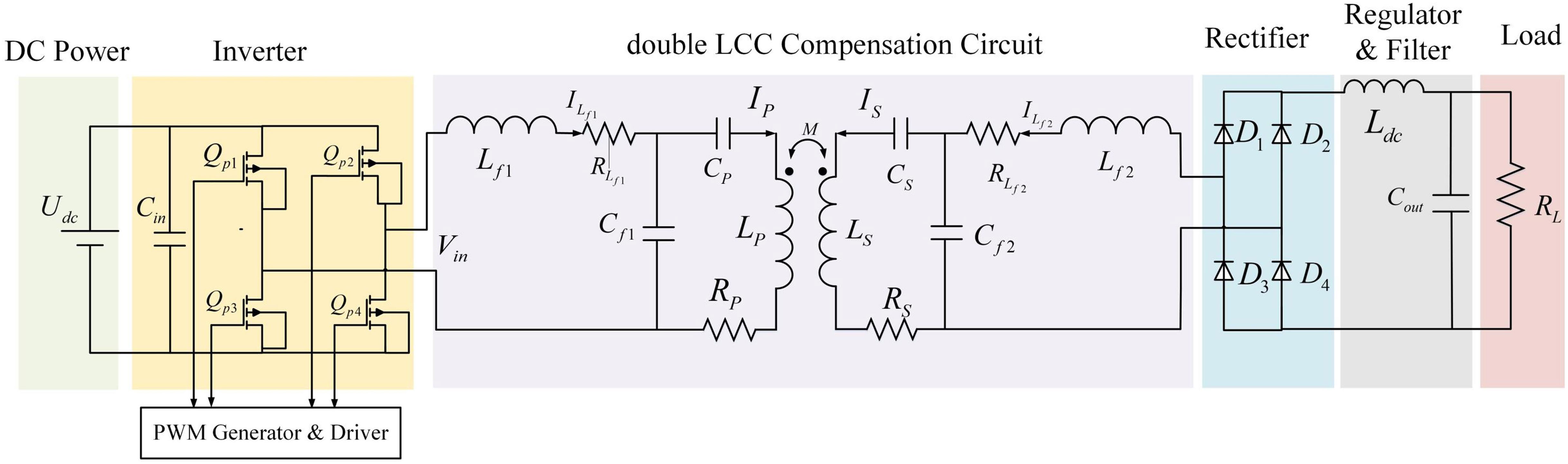
Figure 6 The schematic diagram of the OPCT-NWMC circuit.
The input currents of LCC circuits on both sides are , , and the current flowing through the primary and secondary coils are , . The conditions for system resonance are:
The system adopts a symmetrical design, i.e. Lf1 = Lf2 = Lf, Cf1 = Cf2 = Cf, self-inductances LP = LS, internal resistances of coils, Rp = Rs internal resistances of compensation inductances Rf1 = Rf2.
The primary side power conversion is realized by the full shifting bridge. After the full bridge rectification and filtering on the secondary side, the power is supplied to the secondary load. The zero-voltage zero-current switching (ZVZCS) is realized by using the parasitic capacitance of the circuit itself. IRFB4110 is chosen as the power switch tube. In order to drive the power switch tube, UCC3895Ns are used as the PWM signal generation chips, and IR2110s are used for current amplification. Fast recovery Schottky rectifier diodes MBR30100CT are selected as the rectifiers. A filter inductor and a large capacitor in parallel can reduce the voltage ripple.
4.3 Optical communication design
The optical communication system of OCPT-NWMC is mainly composed of three parts: transmitting device, receiving device, and seawater channel. The principle block diagram is shown in Figure 7. At the transmitting end, the information to be transmitted is encoded and modulation. The modulated wave containing the signal is coupled with the DC source to drive the light source – laser. The light emitted is then collimated by the transmitting optical antenna. The receiving optical antenna receives the signal transmitted in the seawater channel. The optical detection device converts the optical signal into an electrical signal, and then restores the original signal through functional modules such as conditioning, demodulation, decoding, then sends it to the sink.
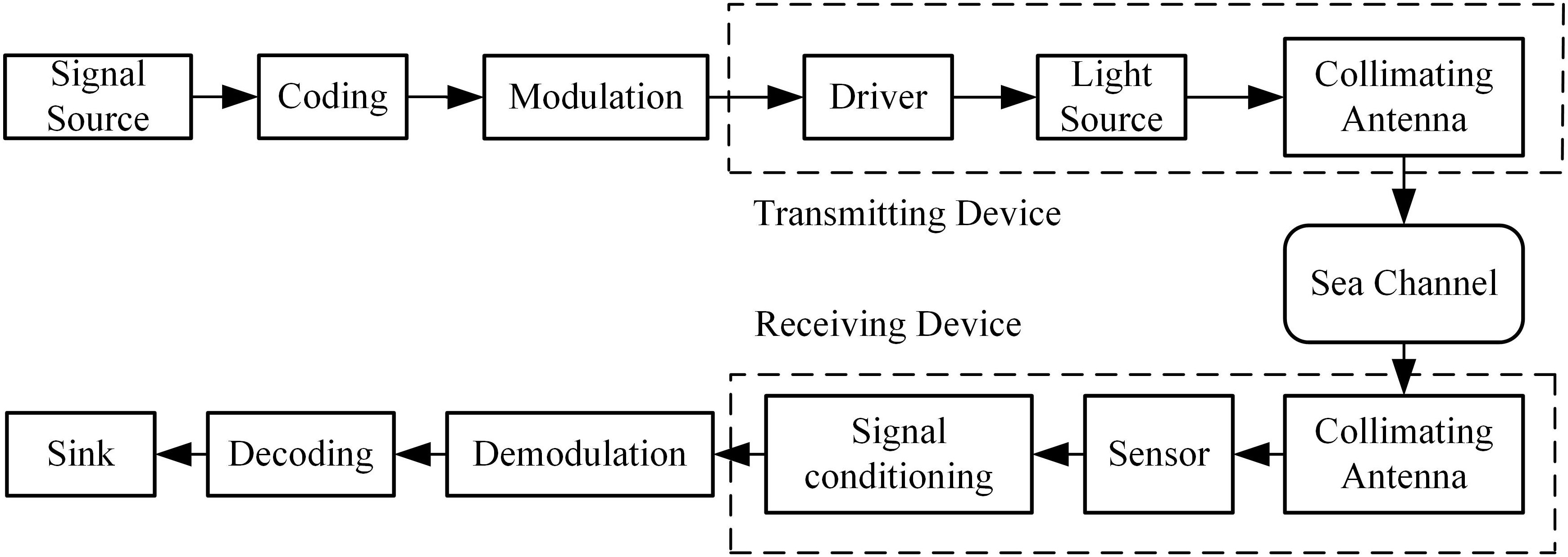
Figure 7 The principle block diagram of optical communication.
As for the implementation, at the transmitting end, the host computer communicates with the transmitting end FPGA chip. The transmitting end FPGA completes signal encoding and DA conversion, which is then connected to the laser tube that emits light. At the receiving end, the PIN tube is connected to the receiving end FPGA. The FPGA completes AD conversion and signal decoding, and then communicates with the host computer.
The connection between the host computer and OCPT-NWMC is realized by asynchronous transmission of UART. In order to solve the speed mismatch between the UART transmission and the modulation algorithm, a First Input First Output (FIFO) pair is used to connect the UART module and the modulation and demodulation module. At the transmitter side, the UART reads data from the host computer, and the OOK modulation algorithm reads the bit stream from the FIFO. “01111110” is selected as the frame header to encapsulate the data. In order to ensure that frame header data does not appear in the data, bit-fill processing is performed in the real data. The specific frame format of the sender is: 0111110 (sync header) + 32bit frame information (frame length, etc.) + data information. After the framed data is converted by DA, the laser tube is driven to emit light by the laser drive circuit. At the receiving end, the signal received by the PIN tube is converted by AD and input to the FPGA demodulation module. The demodulated data is then transmitted to the host computer through the UART. FIFO is also required for matching between the receiving end UART and the demodulation module. UART converts parallel data into serial and adopts asynchronous transmission, and sends the data in frames. A frame of data starts with a low-order start bit, followed by 6~8 data bits, 1 or several high-order stop bits, and finally a parity bit.
5 Prototype of OCPT-NWMC
A prototype of OPCT-NWMC is shown in Figure 8. The circuit board is designed to be circular. Mounting holes and wiring holes are processed. The primary cavity and secondary cavity lengths are both 120mm. The end cap and the cavity are made of aluminum alloy. The primary and secondary optical antennas need to be arranged on the end face of the connector. On the other hand, the magnet and coils for power transfer on both sides also need to be arranged on the end face in order to improve the coupling coefficient. Thus, a light transmitting acrylic plate is designed as an optical antenna. For reducing the radial dimension, the light transmission window is designed with the help of the through hole in the middle of the ferrite pot core. Considering that the laser is sensitive to temperature changes, copper is used to make the laser heat sink. The laser is fixed on the primary light transmitting acrylic board through the heat sink block, and the secondary side receiving board is fixed on the secondary light transmitting acrylic board. If the magnetic cores of OCPT-NWMC are aligned, the laser is automatically aligned. The coils, combined with the optical antennas are fixed together in the nylon coil holder.
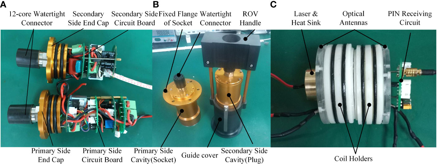
Figure 8 Assembled prototype of OCPT-NWMC [(A)Assembly of circuits and end caps (B)assembly of the connector (C) Assembly of Optical System and Loosely Coupled Coils].
In addition, the insertion force of OCPT-NWMC is simulated. A speed of 10 mm/s is applied at the end of the handle, so that the plug is inserted into the socket along the axial direction. And the end face of the plug is 91mm away from the end face of the socket in the initial state. The force acting on the handle is measured during the insertion process, and the force curve is shown in Figure 9. It can be seen that the maximum insertion force does not exceed 150N, which meets the requirements of underwater insertion and extraction operations under the operation of ROV with gripper.

Figure 9 Force curve during insertion.
6 Experiments of OCPT-NWMC
6.1 Test of CLPT system
The test platform of CLPT system is shown in Figure 10. The programmable power supply is used as the primary side DC power supply. The coils are wound with 22:22 turns. The gap between the two magnetic cores is 3mm.
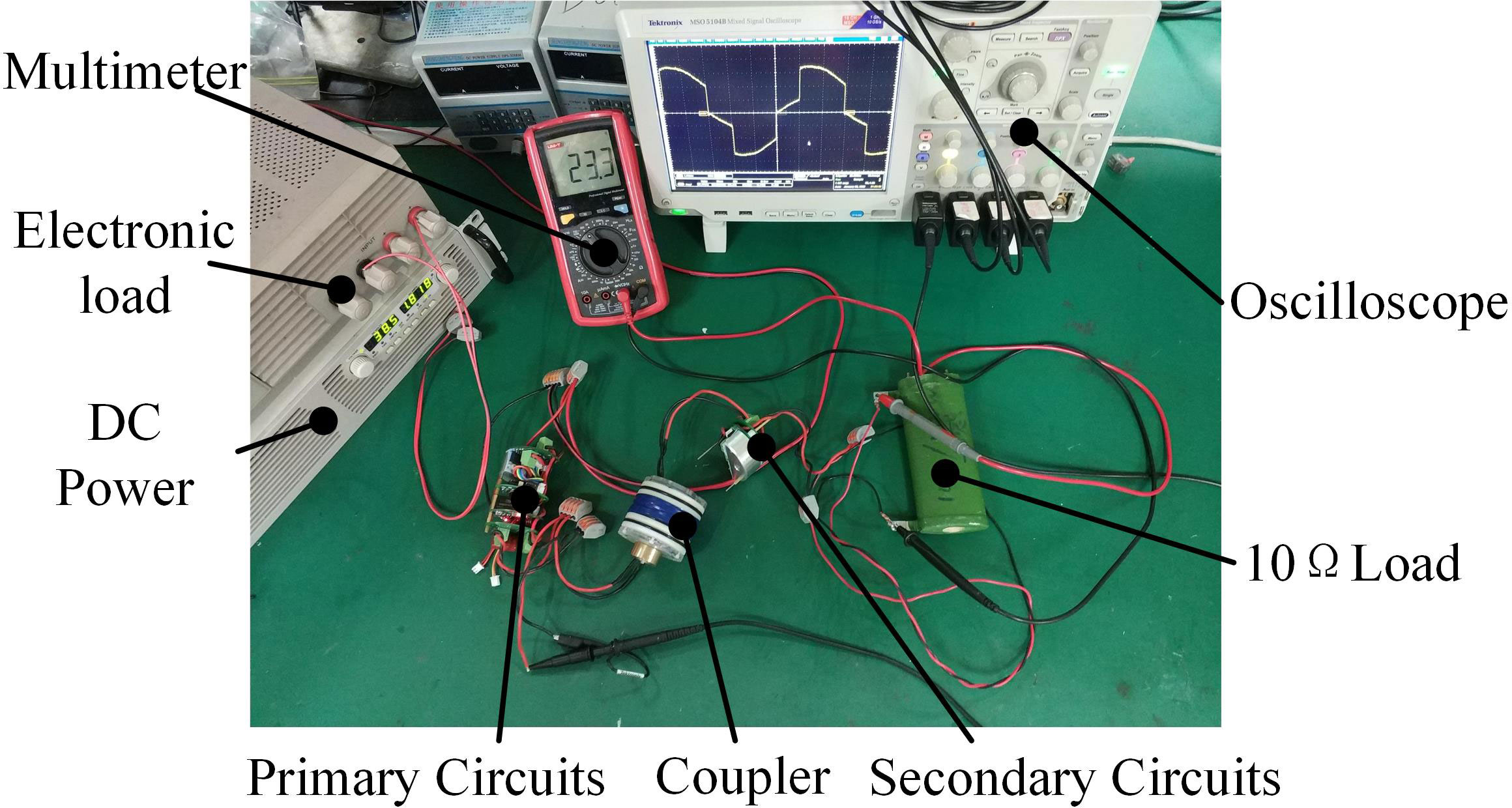
Figure 10 Test platform of CLPT system.
The data curves tested under different operating frequencies when the output connected to a 10Ω resistor are shown in Figure 11. It can be seen that the system can achieve a maximum power transmission of 200W. In the range of 30~100kHz, the overall efficiency can reach more than 80%, and the highest reaches 94%.
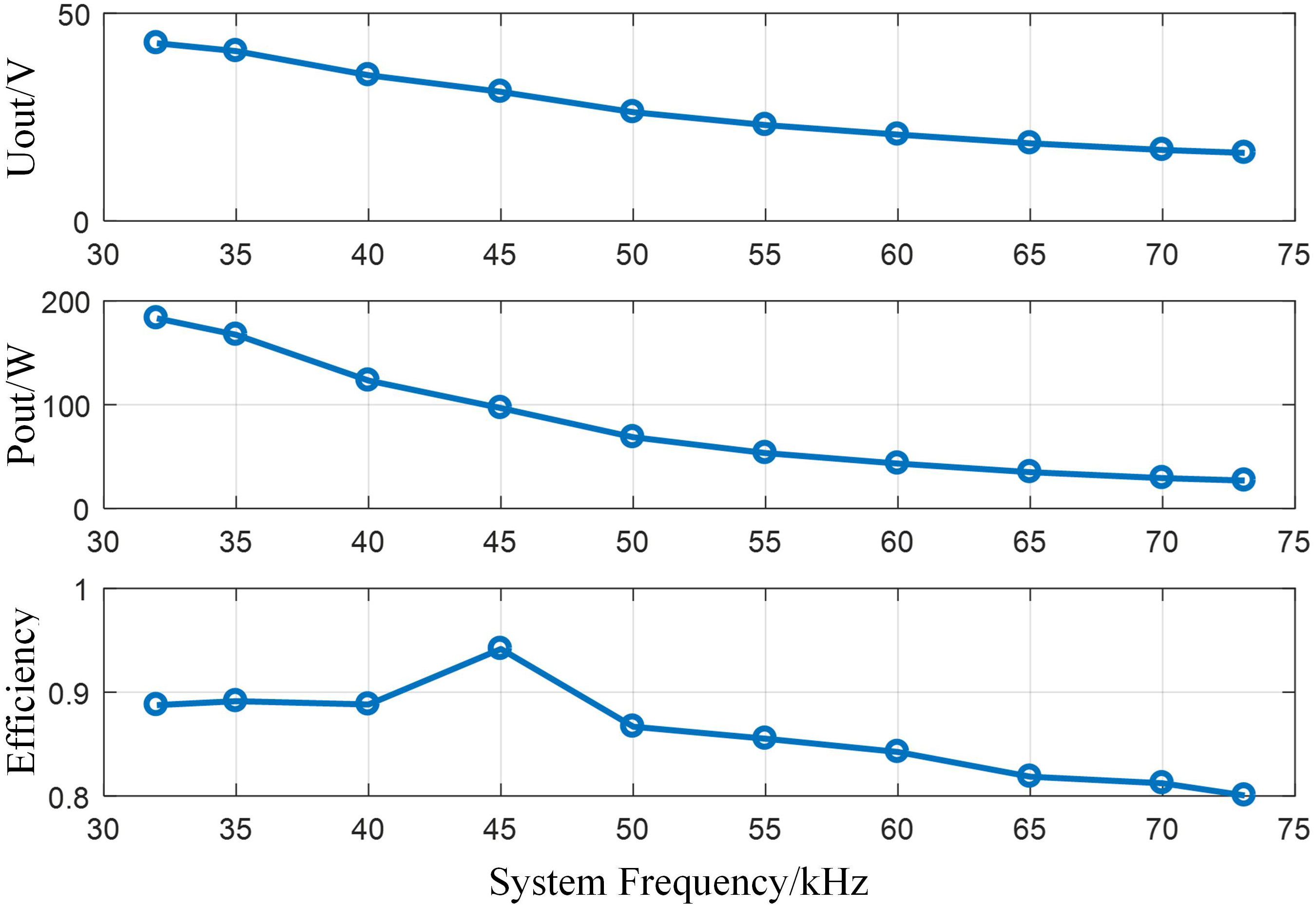
Figure 11 Output performance of 10Ω resistor under different operating frequencies.
The power transmission performance of CLPT system when an electronic load is connected to the output is tested under different load resistances. Figure 12 shows the power transmission performance of CLPT system. It is shown that when the system frequency is 35kHz, OCPT-NWMC has better constant voltage output characteristic. The system transmission frequency is basically greater than 0.8.
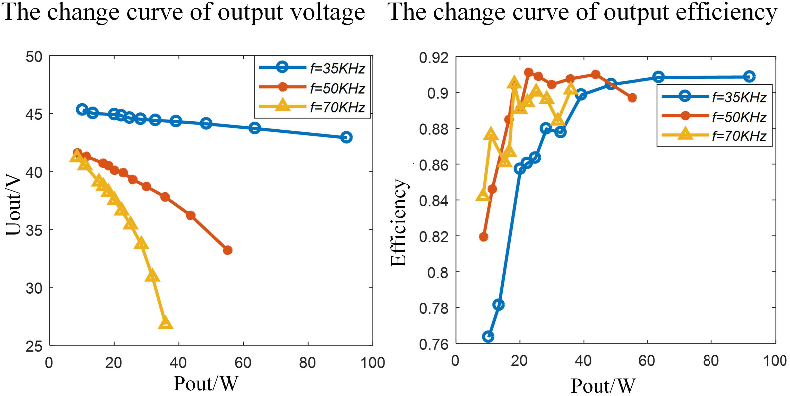
Figure 12 The power transmission performance of CLPT system.
6.2 Test of OCPT-NWMC
After the assembly is completed, a tool experiment is performed on OCPT-NWMC. The signal of the transmitting side PC and the power of the power supply are transmitted to the OCPT-NWMC socket through the primary side watertight cable. And the OCPT-NWMC plug transmits the power and signal to the receiving side PC and electronic load through the secondary side watertight cable. The configuration for the tool experiment of OCPT-NWMC is shown in Figure 13.
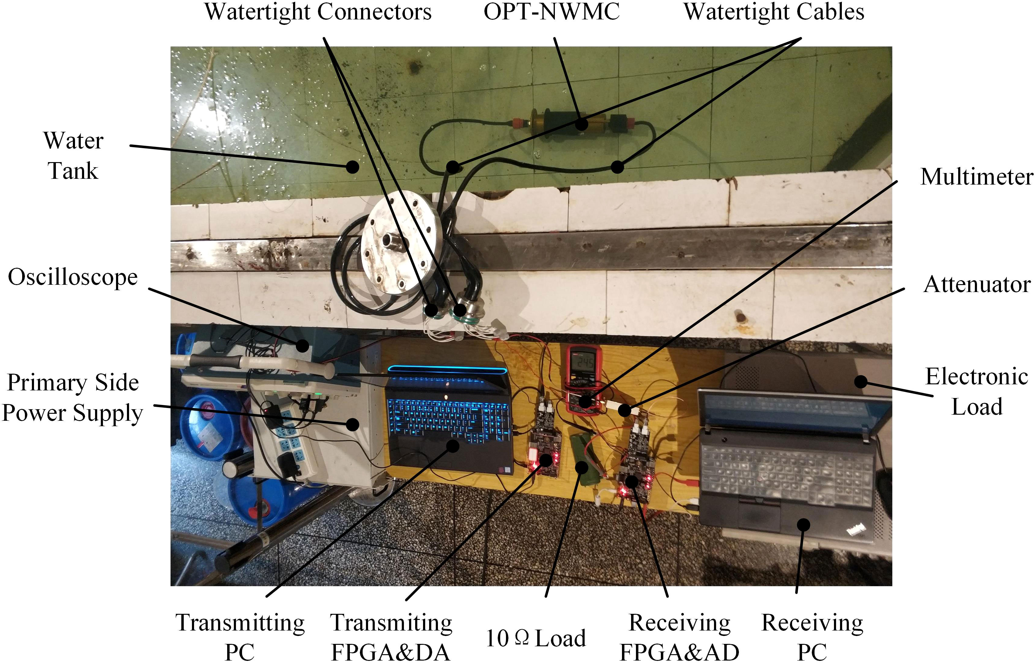
Figure 13 The configuration for the tool experiment of OCPT-NWMC.
The tool is filled with simulated seawater(%3.5 salt water). Adjust the drive frequency of the inverter to 40kHz, the connector was connected to the electronic load. The tests of output performance are carried out in water and in air, respectively. The test results are shown in Figure 14. The results of the test in the air are almost consistent with the results of the test in simulated seawater. However, there exists an obvious difference with the results measured in CLPT test. The reason is that in order to facilitate assembly, a larger gap is left. The potting process also leads to an increase in the gap between two coils, resulting in a decrease of the coupling coefficient. Furthermore, the cavity is a metal shell. High-frequency electromagnetic waves induce eddy currents in the cavity, causing large losses. The solution is to fix the magnetic core, coil, and coil support first, and then potting, so as to reduce the axial spacing and assembly error of the magnetic core as much as possible. And a layer of copper foil can be added to the outer layer of the magnetic core for electromagnetic shielding, reducing the eddy current loss.
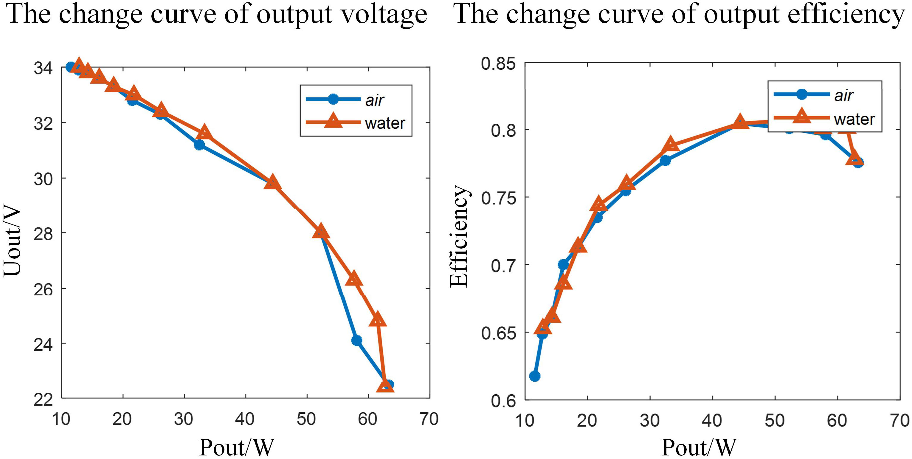
Figure 14 The power transmission performance of OCPT-NWMC in the water tool experiment.
As for optical communication, use programmable power supply powers the FPGA and driver circuits. The drive current of the laser is set to 50mA. The test program is written by ISE software, and the square wave is output from the FPGA at the transmitting end. After DA conversion, it is loaded onto the laser through the driving circuit. An oscilloscope is used to observe the waveform output by the receiver. In order to test the bandwidth of the communication system, square waves with an amplitude of 1Vp-p at different frequencies were sent at the transmitting side. And the output of the transimpedance amplifier at the receiving side was connected to an oscilloscope to check the amplitude and phase of the received signal. The amplitude-frequency response of the system obtained is shown in Figure 15A. It can be seen that the bandwidth of the system can reach about 18MHz. Limited by the test conditions, the bit error rate of the system was not be measured. More accurate system performance results can be obtained by analyzing the actual signal received and processed by the optical receiver. In order to test the transceiver performance, the transmitter continuously sends a string of “non-contact wet mateable connector for optical communication and power transmission” through the serial assistant. Then the string is read from the FIFO at a speed of 10MHz, and load to the laser through DA. After AD sampling at the receiving side, the signal is written into the FIFO, and then read out from the FIFO and sent to the host computer through the serial port assistant. The data received by the serial port assistant at the receiving side is shown in Figure 15B. It is shown that the receiving side correctly recovered the information of the transmitting side without code error. However, when the modulation rate is increased to 15MHz, garbled characters appear.
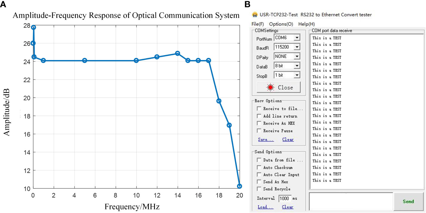
Figure 15 Test of optical communication system (A) Amplitude-Frequency Response of Optical Communication System (B) Serial port assistant of Optical communication system.
7 Conclusion and prospects
At present, the commercial watertight connectors are mainly contact-type. The socket and the plug need to be tightly inserted to realize the transmission of power and signals. Aiming at overcoming the shortcomings of traditional watertight connectors, this paper designed a non-contact wet mateable connector based on contactless power transmission and optical communication. Based on system analysis and design, a prototype of OCPT-NWMC was developed and verified by experimental tests. This system can realize the transmission of 200W power, and the efficiency can reach 94%. The correctness of the transmission and reception of the 10MHz modulation rate system was tested through the serial port. The experiments show the rationality and correctness of the system design, which provides practical reference for the design of underwater wet mateable connector.
This research has certain limitations and the work of this paper can be further deepened and improved, for example, due to the frequency splitting when adopting high-order compensation, it is necessary to use a closed-loop control system to track and optimize the operating frequency; The bandwidth of the transimpedance amplifier at the receiving end limits the system bandwidth, so a transimpedance amplifier with a high gain-bandwidth product can be selected. FPGA with higher system clock and AD and DA can be chosen to increase the bandwidth of hardware circuit. Advanced modulation algorithms such as QAM and OFDM can be used.
Data availability statement
The raw data supporting the conclusions of this article will be made available by the authors, without undue reservation.
Author contributions
ZD: Methodology, Project administration. YZ: Investigation. JH: Writing - Original Draft, Visualization, Validation. BH: Data Curation. BH: Software. All authors contributed to the article and approved the submitted version.
Funding
This work was supported by the National Natural Science Foundation of China (No.51979246), the National Key Research and Development Program of China (No. 2021YFC2800202) and the Major Science and Technology Project of Ningbo.
Conflict of interest
The authors declare that the research was conducted in the absence of any commercial or financial relationships that could be construed as a potential conflict of interest.
Publisher’s note
All claims expressed in this article are solely those of the authors and do not necessarily represent those of their affiliated organizations, or those of the publisher, the editors and the reviewers. Any product that may be evaluated in this article, or claim that may be made by its manufacturer, is not guaranteed or endorsed by the publisher.
References
Ali M. F., Jayakody D. N. K., Chursin Y. A., Affes Soféine, Dmitry S. (2020). Recent advances and future directions on underwater wireless communications. Arch. Comput. Methods Eng. 27 (5), 1379–14125. doi: 10.1007/s11831-019-09354-8
Baer C. M., Alten M., Bixler G., Fredette L., Owens J., Purvinis G., et al. (2009). “Non-contact wet mateable connector,” in OCEANS. (Biloxi, MS, USA: IEEE) 2009, 1–6. doi: 10.23919/oceans.2009.5422298
Best M., Favali P., Beranzoli L. (2014). EMSO: A distributed infrastructure for addressing geohazards and global ocean change. Oceanography 27 (2), 167–695. doi: 10.5670/oceanog.2014.52
Chen Y., Duan Z., Zheng F., Guo Y., Xia Q. (2022). Underwater optical guiding and communication solution for the AUV and seafloor node. Appl. Optics 61 (24), 7059–7705. doi: 10.1364/ao.462678
Christ R. D., Wernli R. L. (2014). “The ROV manual (Second edition),” in The ROV manual, 2nd ed. Eds. Christ R. D., Wernli R. L. (Oxford: Butterworth-Heinemann). doi: 10.1016/B978-0-08-098288-5.00028-2
Doniec M., Rus D. (2010). “BiDirectional optical communication with AquaOptical II,” in 2010 IEEE International Conference on Communication Systems. (Singapore: IEEE). 390–394. doi: 10.1109/iccs.2010.5686513
Doniec M. W., Rus D. (2015) Underwater optical communication system. Available at: https://patents.google.com/patent/US9031413B2/en.
Favali P., Beranzoli L., Italiano F., Migneco E., Musumeci M., Papaleo R. (2011). NEMO-SN1 observatory developments in view of the European research infrastructures EMSO and KM3NET. Nucl. Instruments Methods Phys. Res. Section A: Accelerators Spectrometers Detectors Associated Equip. 626–627 (January), S53–S56. doi: 10.1016/j.nima.2010.04.139
Gati E., Kampitsis G., Manias S. (2017). Variable frequency controller for inductive power transfer in dynamic conditions. IEEE Trans. Power Electron. 32 (2), 1684–1965. doi: 10.1109/TPEL.2016.2555963
Gayathri C.B., Deeksha S., Durga S. D. M., Narendara Raj V. (2015). “Design of high speed underwater optical communication using on-off keying algorithm,” in 2015 International Conference on Communications and Signal Processing (ICCSP). (Melmaruvathur, India: IEEE). 1355–1360. doi: 10.1109/iccsp.2015.7322730
Granger R. P., Baer C. M., Gabriel N. H., Labosky J. J., Galford T. C. (2013). “Non-contact wet mateable connectors for power and data transmission,” in 2013 OCEANS, (San Diego, CA, USA: IEEE). 1–4. doi: 10.23919/OCEANS.2013.6741173
Kaushal H., Kaddoum G. (2016). Underwater optical wireless communication. IEEE Access 4, 1518–1547. doi: 10.1109/access.2016.2552538
Kawaguchi K., Kaneda Y., Araki E. (2008). “The DONET: A real-time seafloor research infrastructure for the precise earthquake and tsunami monitoring,” in OCEANS 2008 - MTS/IEEE Kobe Techno-Ocean. (Kobe, Japan: IEEE), 1–4. doi: 10.1109/oceanskobe.2008.4530918
Khalighi M.-A., Hamza T., Bourennane S., Léon P., Opderbecke J. (2017). Underwater wireless optical communications using silicon photo-multipliers. IEEE Photonics J. 9 (4), 1–105. doi: 10.1109/jphot.2017.2726565
Li S., Li W., Deng J., Nguyen T. D., Mi C. C. (2015). A double-sided LCC compensation network and its tuning method for wireless power transfer. IEEE Trans. Vehicular Technol. 64 (6), 2261–2735. doi: 10.1109/tvt.2014.2347006
Lin Ri, Li D., Zhang T., Lin M. (2019). A non-contact docking system for charging and recovering autonomous underwater vehicle. J. Mar. Sci. Technol. 24 (3), 902–165. doi: 10.1007/s00773-018-0595-6
Lin M., Yang C. (2020). Ocean observation technologies: A review. Chin. J. Mechanical Eng. 33 (1), 325. doi: 10.1186/s10033-020-00449-z
Li S., Qu W., Liu C., Qiu T., Zhao Z. (2019). Survey on high reliability wireless communication for underwater sensor networks. J. Network Comput. Appl. 148 (December), 102446. doi: 10.1016/j.jnca.2019.102446
Li Y., Wang S., Jin C., Zhang Y., Jiang T. (2019). A survey of underwater magnetic induction communications: Fundamental issues, recent advances, and challenges. IEEE Commun. Surveys Tutorials 21 (3), 2466–2487. doi: 10.1109/comst.2019.2897610
Li D., Wang T., Yang C. (2017). A novel designed load adaptive noncontact wet-mate connector for subsea devices. Mar. Technol. Soc. J. 51 (4), 31–405. doi: 10.4031/mtsj.51.4.8
Mikada H., Chave A. D. (2004). “Science requirements as the design drivers for ocean observatories,” in Oceans ‘04 MTS/IEEE Techno-Ocean ‘04. (Kobe, Japan: IEEE), 4, 2164–2169. doi: 10.1109/oceans.2004.1406481
Painter H., Flynn J. (2006). “Current and future wet-mate connector technology developments for scientific seabed observatory applications,” in OCEANS 2006. (Boston, MA, USA: IEEE) 1–6. doi: 10.1109/oceans.2006.306829
Rémouit F., Ruiz-Minguela P., Engström J. (2018). “Review of electrical connectors for underwater applications,” in IEEE Journal of Oceanic Engineering. IEEE, 43 (4), 1037–1475. doi: 10.1109/joe.2017.2745598
Shi J., Li F., Peng S., Cai W., Pan M., Yu H. (2020). Design and analysis of a noninsert wet mateable connector for underwater power and data transfer. Mar. Technol. Soc. J. 54 (1), 65–785. doi: 10.4031/mtsj.54.1.3
Wang C., Yu H.-Y., Zhu Y.-J. (2016). A long distance underwater visible light communication system with single photon avalanche diode. IEEE Photonics J. 8 (5), 1–115. doi: 10.1109/jphot.2016.2602330
Keywords: watertight connector, non-contact wet mateable connector, contactless power transmission, optical communication, seabed observation network
Citation: Duan Z, Zhang Y, Hu J, He B and Yang C (2023) Research on non-contact wet mateable connector for optical communication and power transmission. Front. Mar. Sci. 10:1100653. doi: 10.3389/fmars.2023.1100653
Received: 17 November 2022; Accepted: 19 January 2023;
Published: 02 February 2023.
Edited by:
Shaowei Zhang, Institute of Deep-Sea Science and Engineering (CAS), ChinaReviewed by:
Shaoqiong Yang, Tianjin University, ChinaGiorgio Riccobene, Laboratori Nazionali del Sud (INFN), Italy
Copyright © 2023 Duan, Zhang, Hu, He and Yang. This is an open-access article distributed under the terms of the Creative Commons Attribution License (CC BY). The use, distribution or reproduction in other forums is permitted, provided the original author(s) and the copyright owner(s) are credited and that the original publication in this journal is cited, in accordance with accepted academic practice. No use, distribution or reproduction is permitted which does not comply with these terms.
*Correspondence: Canjun Yang, eWNqQHpqdS5lZHUuY24=